CN112659645B - Corrugated case preparation mould pressing processing apparatus - Google Patents
Corrugated case preparation mould pressing processing apparatus Download PDFInfo
- Publication number
- CN112659645B CN112659645B CN202011332481.8A CN202011332481A CN112659645B CN 112659645 B CN112659645 B CN 112659645B CN 202011332481 A CN202011332481 A CN 202011332481A CN 112659645 B CN112659645 B CN 112659645B
- Authority
- CN
- China
- Prior art keywords
- rod
- cutting
- plate
- block
- gluing
- Prior art date
- Legal status (The legal status is an assumption and is not a legal conclusion. Google has not performed a legal analysis and makes no representation as to the accuracy of the status listed.)
- Active
Links
Images


Landscapes
- Making Paper Articles (AREA)
Abstract
本发明涉及一种瓦楞纸箱制作模压处理装置,包括底板、塑型机构、涂胶机构和裁剪机构,所述的底板上端安装有塑型机构,塑型机构后方设置有涂胶机构,涂胶机构安装在底板上,涂胶机构上方设置有裁剪机构,裁剪机构安装在底板上。本发明可以解决有的设备在针对瓦楞纸箱进行模压成型时,不能确保瓦楞纸紧贴设备进行折叠,瓦楞纸在折叠时易出现折叠长度不一致的现象,从而降低了瓦楞纸箱的成型效果,折叠后的瓦楞纸箱易出现不规则的现象,导致了材料的浪费,同时,不能对瓦楞纸箱两端同时进行开口处理,从而增加了瓦楞纸箱两端开口的工作步骤,降低了瓦楞纸箱成型的效率等问题。
The invention relates to a molding processing device for making corrugated carton boxes, comprising a bottom plate, a molding mechanism, a gluing mechanism and a cutting mechanism. The utility model is installed on the base plate, a cutting mechanism is arranged above the gluing mechanism, and the cutting mechanism is installed on the base plate. The invention can solve the problem that some equipment cannot ensure that the corrugated paper is folded closely to the equipment when the corrugated box is molded, and the folded length of the corrugated paper is likely to be inconsistent when folded, thereby reducing the molding effect of the corrugated box. The box is prone to irregularities, which leads to waste of materials. At the same time, it is impossible to open the two ends of the corrugated box at the same time, which increases the working steps of opening the two ends of the corrugated box and reduces the efficiency of the corrugated box.
Description
技术领域technical field
本发明涉及纸箱成型技术领域,特别涉及一种瓦楞纸箱制作模压处理装置。The invention relates to the technical field of carton forming, in particular to a molding processing device for making corrugated carton boxes.
背景技术Background technique
瓦楞纸板经过模切、压痕、钉箱或粘箱制成瓦楞纸箱,瓦楞纸箱是一种应用最广的包装制品,用量一直是各种包装制品之首;半个多世纪以来,瓦楞纸箱以其优越的使用性能和良好的加工性能逐渐取代了木箱等运输包装容器,成为运输包装的主力军,它除了保护商品、便于仓储、运输之外,还起到美化商品,宣传商品的作用;瓦楞纸箱属于绿色环保产品,它利于环保,利于装卸运输。Corrugated cardboard is made into corrugated boxes by die-cutting, creasing, nail boxing or sticking. Its superior performance and good processing performance have gradually replaced wooden boxes and other transportation packaging containers and become the main force of transportation packaging. In addition to protecting commodities, facilitating storage and transportation, it also plays a role in beautifying and promoting commodities; Corrugated boxes are green and environmentally friendly products, which are conducive to environmental protection and loading, unloading and transportation.
目前,现有的设备在针对瓦楞纸箱进行模压成型时,通常存在以下不足:1、现有设备在瓦楞纸箱成型过程中不能确保瓦楞纸紧贴设备进行折叠,瓦楞纸在折叠时易出现折叠长度不一致的现象,从而降低了瓦楞纸箱的成型效果,折叠后的瓦楞纸箱易出现不规则的现象,导致了材料的浪费;2、现有设备不能对瓦楞纸箱两端同时进行开口处理,从而增加了瓦楞纸箱两端开口的工作步骤,降低了瓦楞纸箱成型的效率。At present, the existing equipment usually has the following deficiencies when molding corrugated boxes: 1. The existing equipment cannot ensure that the corrugated paper is folded closely to the equipment during the molding process of the corrugated box, and the corrugated paper is prone to inconsistent folding lengths during folding. This phenomenon reduces the forming effect of the corrugated box, and the folded corrugated box is prone to irregularities, resulting in waste of materials; 2. The existing equipment cannot open both ends of the corrugated box at the same time, thus increasing the number of corrugated boxes. The working steps of opening at both ends reduce the efficiency of corrugated box forming.
发明内容SUMMARY OF THE INVENTION
(一)要解决的技术问题(1) Technical problems to be solved
本发明可以解决现有的设备在针对瓦楞纸箱进行模压成型时,不能确保瓦楞纸紧贴设备进行折叠,瓦楞纸在折叠时易出现折叠长度不一致的现象,从而降低了瓦楞纸箱的成型效果,折叠后的瓦楞纸箱易出现不规则的现象,导致了材料的浪费,同时,不能对瓦楞纸箱两端同时进行开口处理,从而增加了瓦楞纸箱两端开口的工作步骤,降低了瓦楞纸箱成型的效率等难题。The invention can solve the problem that the existing equipment cannot ensure that the corrugated paper is folded closely to the equipment when the corrugated box is molded, and the corrugated paper is prone to the phenomenon that the folding length is inconsistent during folding, thereby reducing the molding effect of the corrugated box. Corrugated boxes are prone to irregularities, resulting in waste of materials. At the same time, it is impossible to open both ends of the corrugated box at the same time, thus increasing the working steps of opening the two ends of the corrugated box and reducing the efficiency of corrugated box forming.
(二)技术方案(2) Technical solutions
为了实现上述目的,本发明采用以下技术方案,一种瓦楞纸箱制作模压处理装置,包括底板、塑型机构、涂胶机构和裁剪机构,所述的底板上端安装有塑型机构,塑型机构后方设置有涂胶机构,涂胶机构安装在底板上,涂胶机构上方设置有裁剪机构,裁剪机构安装在底板上。In order to achieve the above purpose, the present invention adopts the following technical solutions, a corrugated box manufacturing molding processing device, including a bottom plate, a molding mechanism, a gluing mechanism and a cutting mechanism, and a molding mechanism is installed on the upper end of the bottom plate. A gluing mechanism is provided, the gluing mechanism is installed on the base plate, a cutting mechanism is arranged above the gluing mechanism, and the cutting mechanism is installed on the base plate.
所述的塑型机构包括顶升推杆、收卷框、收卷辊、塑形带、连接架、牵引杆和转动辊,所述的底板上端安装有顶升推杆,顶升推杆上端安装有连接板,连接板前端安装有收卷框,收卷框前侧壁上设置有方形孔,收卷框内部设置有收卷辊,收卷辊通过扭簧与收卷框端壁内端面连接,收卷辊上连接有塑形带,塑形带另一端穿过方形孔连接有连接架,连接架呈U型结构,连接架侧壁通过轴承连接有牵引杆,牵引杆通过滑动配合的方式与裁剪机构连接,牵引杆中部外表面通过轴承连接有转动辊,具体工作时,首先,当瓦楞板放置在裁剪机构上,之后,手动启动顶升推杆,顶升推杆通过连接板带动收卷框运动到瓦楞板下端,连接板对进行夹紧,最后,裁剪机构通过牵引杆带动转动辊进行转动,转动辊带动瓦楞板紧贴裁剪机构进行折叠处理。The shaping mechanism includes a lifting push rod, a winding frame, a winding roller, a shaping belt, a connecting frame, a traction rod and a rotating roller. The upper end of the bottom plate is provided with a lifting push rod, and the upper end of the lifting push rod A connecting plate is installed, a winding frame is installed at the front end of the connecting plate, a square hole is arranged on the front side wall of the winding frame, a winding roller is arranged inside the winding frame, and the winding roller is connected to the inner end surface of the end wall of the winding frame through a torsion spring. Connection, the rewinding roller is connected with a shaping belt, the other end of the shaping belt is connected with a connecting frame through a square hole, the connecting frame is in a U-shaped structure, the side wall of the connecting frame is connected with a traction rod through a bearing, and the traction rod is connected by a sliding fit. The method is connected with the cutting mechanism, and the middle outer surface of the drawbar is connected with a rotating roller through a bearing. When working, first, when the corrugated board is placed on the cutting mechanism, then manually start the jacking push rod, and the jacking push rod is driven by the connecting plate. The winding frame moves to the lower end of the corrugated board, and the connecting plates are clamped. Finally, the cutting mechanism drives the rotating roller to rotate through the traction rod, and the rotating roller drives the corrugated board to be close to the cutting mechanism for folding.
所述的裁剪机构包括支撑板、驱动电机、连接杆、裁剪块、支撑块、方形块、裁剪单元、进给电机和主动齿轮,所述的底板上端左右对称设置有支撑板,左侧支撑板安装在底板上,右侧支撑板通过滑动配合的方式与底板连接,右侧支撑板外端面靠近下侧通过螺纹配合的方式连接有锁紧螺杆,左侧支撑板外端面安装有驱动电机,驱动电机的输出轴上安装有连接杆,连接杆通过滑动配合的方式与牵引杆连接,支撑板内端面安装有裁剪块,裁剪块下方前后对称设置有支撑块,支撑块安装在支撑板内端面上,支撑块上端设置有直角梯形凸起,左侧裁剪块内端安装有方形块,裁剪块上端面设置有矩形槽,矩形槽端壁通过轴承连接有裁剪单元,裁剪单元后侧设置有进给电机,进给电机通过电机座安装在矩形槽下壁上,进给电机的输出轴上安装有主动齿轮,主动齿轮与裁剪单元齿轮啮合,具体工作时,首先,通过人工的方式将瓦楞板放置在支撑块上,之后,人工启动驱动电机,驱动电机通过牵引杆带动转动辊对瓦楞板进行折叠,最后,手动启动进给电机,进给电机通过主动齿轮带动裁剪单元对瓦楞纸进行切割处理。The cutting mechanism includes a supporting plate, a driving motor, a connecting rod, a cutting block, a supporting block, a square block, a cutting unit, a feeding motor and a driving gear. The upper end of the bottom plate is symmetrically provided with a supporting plate, and the left supporting plate is Installed on the bottom plate, the right support plate is connected with the bottom plate by sliding fit, the outer end surface of the right support plate is close to the lower side and is connected with a locking screw by screw fit, and the outer end surface of the left support plate is installed with a drive motor, which drives the A connecting rod is installed on the output shaft of the motor, and the connecting rod is connected with the traction rod by sliding fit. A cutting block is installed on the inner end face of the support plate, and a support block is symmetrically arranged in the front and rear below the cutting block, and the support block is installed on the inner end face of the support plate. , The upper end of the support block is provided with a right-angled trapezoidal protrusion, the inner end of the left cutting block is installed with a square block, the upper end surface of the cutting block is provided with a rectangular groove, the end wall of the rectangular groove is connected with a cutting unit through a bearing, and the rear side of the cutting unit is provided with a feeding The motor, the feeding motor is installed on the lower wall of the rectangular slot through the motor seat, and the output shaft of the feeding motor is installed with a driving gear, which meshes with the cutting unit gear. When working, first, place the corrugated board manually. On the support block, then manually start the drive motor, the drive motor drives the rotating roller to fold the corrugated board through the traction rod, and finally, the feeding motor is manually started, and the feeding motor drives the cutting unit to cut the corrugated paper through the driving gear.
所述的裁剪单元包括传动螺杆、转动齿轮、圆板、顶升杆、上升杆、连接弹簧、顶升块和裁剪支链,所述的传动螺杆通过轴承安装在矩形槽端壁上,传动螺杆外表面安装有转动齿轮,转动齿轮与主动齿轮啮合,转动齿轮内侧设置有连板,连板与传动螺杆螺纹连接,连板下端安装有圆板,圆板上均匀设置有截面呈弧形的通孔,通孔呈环形分布,通孔内部设置有顶升杆,顶升杆安装在裁剪块上,顶升杆外侧设置有上升杆,上升杆通过滑动配合的方式与圆板连接,上升杆内端安装有顶升块,顶升块下端面设置斜面,斜面与顶升杆滑动连接,顶升块与圆板之间连接有连接弹簧,上升杆上端安装有裁剪支链,具体工作时,转动齿轮通过传动螺杆带动圆板进行移动,圆板带动上升杆进行移动,上升杆通过顶升杆带动裁剪支链对瓦楞板进行裁剪。The cutting unit includes a driving screw, a rotating gear, a circular plate, a lifting rod, a lifting rod, a connecting spring, a lifting block and a cutting branch chain. The driving screw is installed on the end wall of the rectangular groove through a bearing, and the driving screw A rotating gear is installed on the outer surface, the rotating gear meshes with the driving gear, a connecting plate is arranged on the inner side of the rotating gear, and the connecting plate is threadedly connected with the transmission screw. The through holes are arranged in a ring shape, a jacking rod is arranged inside the through hole, the jacking rod is installed on the cutting block, and a rising rod is arranged on the outside of the jacking rod. A jacking block is installed at the end, an inclined plane is set on the lower end surface of the jacking block, the inclined plane is slidably connected with the jacking rod, a connecting spring is connected between the jacking block and the circular plate, and a cutting branch chain is installed on the upper end of the ascending rod. The gear drives the circular plate to move through the transmission screw, the circular plate drives the rising rod to move, and the rising rod drives the cutting branch chain to cut the corrugated board through the lifting rod.
作为本发明的一种优选技术方案,所述的涂胶机构包括电动推杆、涂胶板、涂胶框和气泵,所述的底板上端安装有电动推杆,电动推杆上端安装有涂胶板,涂胶板上端安装有涂胶框,涂胶框后侧壁上设置有进胶口,进胶口通过滑动配合的方式连接有密封盖,涂胶框后侧壁靠近下侧连接有气泵,气泵安装在涂胶板上,涂胶框上端均匀设置有喷头,具体工作时,首先,在瓦楞板放置在支撑块上,人工将胶注入涂胶框内,之后,手动启动电动推杆,电动推杆通过涂胶板带动涂胶框运动到瓦楞板下端,最后,手动启动气泵,气泵将胶通过喷头涂抹至瓦楞纸下端。As a preferred technical solution of the present invention, the gluing mechanism includes an electric push rod, a gluing plate, a gluing frame and an air pump, an electric push rod is installed on the upper end of the bottom plate, and a glue gluing rod is installed on the upper end of the electric push rod. The upper end of the gluing plate is equipped with a gluing frame, and a glue inlet is arranged on the back side wall of the gluing frame. , The air pump is installed on the gluing plate, and the upper end of the gluing frame is evenly equipped with a nozzle. When working, first, place the corrugated plate on the support block, manually inject the glue into the gluing frame, and then manually start the electric push rod, The electric push rod drives the gluing frame to the lower end of the corrugated board through the gluing plate. Finally, the air pump is manually started, and the air pump applies the glue to the lower end of the corrugated card through the nozzle.
作为本发明的一种优选技术方案,所述的裁剪支链包括裁剪刀、限位板、裁切刀、复位弹簧、推挤块和推挤弹簧,所述的上升杆外端对称安装有裁剪刀,裁剪刀上端安装有限位板,限位板呈V字形,裁剪刀之间设置有裁切刀,裁切刀与上升杆滑动连接,裁切刀与上升弹簧之间连接有复位弹簧,裁切刀下端设置有推挤块,推挤块通过滑动配合的方式与上升杆连接,推挤块与上升杆之间连接有推挤弹簧,推挤块远离上升杆的一端设置有圆柱杆,具体工作时,首先,上升杆带动裁剪刀对瓦楞纸进行切割,之后,推挤块与方形块配合带动裁切刀对切割后的瓦楞纸进行裁剪,最后,上升杆带动裁剪刀进行复位。As a preferred technical solution of the present invention, the cutting branch chain includes a cutting knife, a limit plate, a cutting knife, a return spring, a pushing block and a pushing spring, and the outer end of the rising rod is symmetrically installed with a cutting knife Scissors, a limit plate is installed on the upper end of the cutting knife, the limit plate is V-shaped, a cutting knife is arranged between the cutting knives, the cutting knife is slidably connected with the rising rod, and a return spring is connected between the cutting knife and the rising spring, and the cutting knife is connected with the rising spring. The lower end of the cutter is provided with a pushing block, the pushing block is connected with the rising rod by sliding fit, a pushing spring is connected between the pushing block and the rising rod, and the end of the pushing block away from the rising rod is provided with a cylindrical rod. When working, first, the rising rod drives the cutting knife to cut the corrugated paper, then the pushing block and the square block cooperate to drive the cutting knife to cut the corrugated paper after cutting, and finally, the rising rod drives the cutting knife to reset.
作为本发明的一种优选技术方案,所述的支撑板上设置有U型滑孔,U型滑孔通过滑动配合的方式与牵引杆连接,具体工作时,U型滑孔起到对牵引杆进行限位的功能。As a preferred technical solution of the present invention, the support plate is provided with a U-shaped sliding hole, and the U-shaped sliding hole is connected with the drawbar by sliding fit. Limit function.
作为本发明的一种优选技术方案,所述的裁剪块中部设置有X形滑槽,X形滑槽侧壁靠近方形块的处安装有顶升杆,X形滑槽与上升杆滑动连接,X形滑槽中部设置有圆形滑槽,圆形滑槽与圆板滑动连接,具体工作时,X形滑槽起到滑动限位的功能。As a preferred technical solution of the present invention, an X-shaped chute is arranged in the middle of the cutting block, a lifting rod is installed on the side wall of the X-shaped chute near the square block, and the X-shaped chute is slidably connected with the lifting rod, A circular chute is arranged in the middle of the X-shaped chute, and the circular chute is slidably connected to the circular plate. During specific work, the X-shaped chute functions as a sliding limit.
作为本发明的一种优选技术方案,所述的顶升杆呈L型结构,顶升杆下壁上端设置有梯形凸块,梯形凸块与顶升块上的斜面滑动配合,上升杆侧壁上均匀设置有滚珠,滚珠与X形滑槽侧壁滑动连接,具体工作时,梯形凸块与顶升块上的斜面滑动配合起到带动上升杆顶升的功能。As a preferred technical solution of the present invention, the jacking rod has an L-shaped structure, and the upper end of the lower wall of the jacking rod is provided with a trapezoidal bump, and the trapezoidal bump is slidably matched with the inclined surface on the jacking block, and the side wall of the lifting rod is slidably matched. The balls are evenly arranged on the top, and the balls are slidably connected to the side walls of the X-shaped chute. When working, the trapezoidal bumps and the inclined planes on the lifting block slide and cooperate to drive the lifting rod to lift.
作为本发明的一种优选技术方案,所述的连接杆上设置有滑槽,滑槽通过滑动配合的方式与牵引杆连接,具体工作时,滑槽起到带动牵引杆进行移动的功能。As a preferred technical solution of the present invention, the connecting rod is provided with a chute, and the chute is connected with the drawbar by sliding fit. When working, the chute plays a function of driving the drawbar to move.
(三)有益效果(3) Beneficial effects
1.本发明提供的瓦楞纸箱制作模压处理装置,所采用的塑型机构在瓦楞纸箱成型过程中可以确保瓦楞纸紧贴设备进行折叠,避免瓦楞纸在折叠时出现折叠长度不一致的现象,从而确保了瓦楞纸箱的成型效果,避免了折叠后的瓦楞纸箱出现不规则的现象,减少了材料的浪费;1. The corrugated box production molding processing device provided by the present invention, the adopted molding mechanism can ensure that the corrugated paper is folded close to the equipment during the corrugated box forming process, so as to avoid the phenomenon that the folded length of the corrugated paper is inconsistent during folding, thereby ensuring that the corrugated paper is folded. The forming effect of the box avoids the irregular phenomenon of the folded corrugated box and reduces the waste of materials;
2.本发明提供的瓦楞纸箱制作模压处理装置,所采用的裁剪机构可以在瓦楞纸箱折叠后同时对瓦楞纸箱两端进行开口处理,从而降低了瓦楞纸箱两端开口的工作步骤,提高了瓦楞纸箱成型的效率。2. The corrugated box production molding processing device provided by the present invention adopts the cutting mechanism that can open the two ends of the corrugated box after the corrugated box is folded, thereby reducing the working steps of opening the two ends of the corrugated box and improving the corrugated box. molding efficiency.
附图说明Description of drawings
下面结合附图和实施例对本发明进一步说明。The present invention will be further described below in conjunction with the accompanying drawings and embodiments.
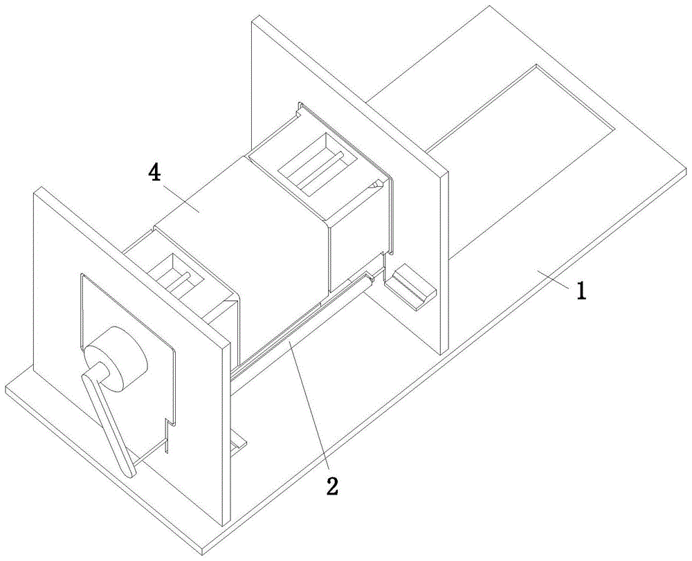
图1是本发明的立体结构示意图;Fig. 1 is the three-dimensional structure schematic diagram of the present invention;
图2是本发明的主视图;Fig. 2 is the front view of the present invention;
图3是本发明的左视图;Fig. 3 is the left side view of the present invention;
图4是本发明图2中A-A的剖视图;Fig. 4 is the sectional view of A-A in Fig. 2 of the present invention;
图5是本发明图2中B-B的剖视图;Fig. 5 is the sectional view of B-B in Fig. 2 of the present invention;
图6是本发明图3中C-C的剖视图;Fig. 6 is the sectional view of C-C in Fig. 3 of the present invention;
图7是本发明图6中N向的放大图;Fig. 7 is the enlarged view of N direction in Fig. 6 of the present invention;
图8是本发明图上升杆、连接弹簧、顶升块和裁剪支链的机构示意剖视图。8 is a schematic cross-sectional view of the mechanism of the lifting rod, the connecting spring, the lifting block and the cutting branch chain according to the present invention.
具体实施方式Detailed ways
以下结合附图对本发明的实施例进行详细说明,但是本发明可以由权利要求限定和覆盖的多种不同方式实施。The embodiments of the present invention are described in detail below with reference to the accompanying drawings, but the present invention can be implemented in many different ways as defined and covered by the claims.
如图1至图8所示,一种瓦楞纸箱制作模压处理装置,包括底板1、塑型机构2、涂胶机构3和裁剪机构4,所述的底板1上端安装有塑型机构2,塑型机构2后方设置有涂胶机构3,涂胶机构3安装在底板1上,涂胶机构3上方设置有裁剪机构4,裁剪机构4安装在底板1上。As shown in Fig. 1 to Fig. 8, a corrugated box manufacturing molding processing device includes a
所述的塑型机构2包括顶升推杆21、收卷框22、收卷辊23、塑形带24、连接架25、牵引杆26和转动辊27,所述的底板1上端安装有顶升推杆21,顶升推杆21上端安装有连接板,连接板前端安装有收卷框22,收卷框22前侧壁上设置有方形孔,收卷框22内部设置有收卷辊23,收卷辊23通过扭簧与收卷框22端壁内端面连接,收卷辊23上连接有塑形带24,塑形带24另一端穿过方形孔连接有连接架25,连接架25呈U型结构,连接架25侧壁通过轴承连接有牵引杆26,牵引杆26通过滑动配合的方式与裁剪机构4连接,牵引杆26中部外表面通过轴承连接有转动辊27,具体工作时,首先,当瓦楞板放置在裁剪机构4上,之后,手动启动顶升推杆21,顶升推杆21通过连接板带动收卷框22运动到瓦楞板下端,连接板对进行夹紧,最后,裁剪机构4通过牵引杆26带动转动辊27进行转动,转动辊27带动瓦楞板紧贴裁剪机构4进行折叠处理。The
所述的涂胶机构3包括电动推杆31、涂胶板32、涂胶框33和气泵34,所述的底板1上端安装有电动推杆31,电动推杆31上端安装有涂胶板32,涂胶板32上端安装有涂胶框33,涂胶框33后侧壁上设置有进胶口,进胶口通过滑动配合的方式连接有密封盖,涂胶框33后侧壁靠近下侧连接有气泵34,气泵34安装在涂胶板32上,涂胶框33上端均匀设置有喷头,具体工作时,首先,在瓦楞板放置在支撑块45上,人工将胶注入涂胶框33内,之后,手动启动电动推杆31,电动推杆31通过涂胶板32带动涂胶框33运动到瓦楞板下端,最后,手动启动气泵34,气泵34将胶通过喷头涂抹至瓦楞纸下端。The
所述的裁剪机构4包括支撑板41、驱动电机42、连接杆43、裁剪块44、支撑块45、方形块46、裁剪单元47、进给电机48和主动齿轮49,所述的底板1上端左右对称设置有支撑板41,左侧支撑板41安装在底板1上,右侧支撑板41通过滑动配合的方式与底板1连接,右侧支撑板41外端面靠近下侧通过螺纹配合的方式连接有锁紧螺杆,左侧支撑板41外端面安装有驱动电机42,驱动电机42的输出轴上安装有连接杆43,连接杆43通过滑动配合的方式与牵引杆26连接,支撑板41内端面安装有裁剪块44,裁剪块44下方前后对称设置有支撑块45,支撑块45安装在支撑板41内端面上,支撑块45上端设置有直角梯形凸起,左侧裁剪块44内端安装有方形块46,裁剪块44上端面设置有矩形槽,矩形槽端壁通过轴承连接有裁剪单元47,裁剪单元47后侧设置有进给电机48,进给电机48通过电机座安装在矩形槽下壁上,进给电机48的输出轴上安装有主动齿轮49,主动齿轮49与裁剪单元47齿轮啮合,具体工作时,首先,通过人工的方式将瓦楞板放置在支撑块45上,之后,人工启动驱动电机42,驱动电机42通过牵引杆26带动转动辊27对瓦楞板进行折叠,最后,手动启动进给电机48,进给电机48通过主动齿轮49带动裁剪单元47对瓦楞纸进行切割处理。The
所述的支撑板41上设置有U型滑孔,U型滑孔通过滑动配合的方式与牵引杆26连接,具体工作时,U型滑孔起到对牵引杆26进行限位的功能。The
所述的连接杆43上设置有滑槽,滑槽通过滑动配合的方式与牵引杆26连接,具体工作时,滑槽起到带动牵引杆26进行移动的功能。The connecting
所述的裁剪块44中部设置有X形滑槽,X形滑槽侧壁靠近方形块46的处安装有顶升杆474,X形滑槽与上升杆475滑动连接,X形滑槽中部设置有圆形滑槽,圆形滑槽与圆板473滑动连接,具体工作时,X形滑槽起到滑动限位的功能。The middle of the cutting
所述的裁剪单元47包括传动螺杆471、转动齿轮472、圆板473、顶升杆474、上升杆475、连接弹簧476、顶升块477和裁剪支链478,所述的传动螺杆471通过轴承安装在矩形槽端壁上,传动螺杆471外表面安装有转动齿轮472,转动齿轮472与主动齿轮49啮合,转动齿轮472内侧设置有连板,连板与传动螺杆471螺纹连接,连板下端安装有圆板473,圆板473上均匀设置有截面呈弧形的通孔,通孔呈环形分布,通孔内部设置有顶升杆474,顶升杆474安装在裁剪块44上,顶升杆474外侧设置有上升杆475,上升杆475通过滑动配合的方式与圆板473连接,上升杆475内端安装有顶升块477,顶升块477下端面设置斜面,斜面与顶升杆474滑动连接,顶升块477与圆板473之间连接有连接弹簧476,上升杆475上端安装有裁剪支链478,具体工作时,转动齿轮472通过传动螺杆471带动圆板473进行移动,圆板473带动上升杆475进行移动,上升杆475通过顶升杆474带动裁剪支链478对瓦楞板进行裁剪。The cutting
所述的顶升杆474呈L型结构,顶升杆474下壁上端设置有梯形凸块,梯形凸块与顶升块477上的斜面滑动配合,上升杆475侧壁上均匀设置有滚珠,滚珠与X形滑槽侧壁滑动连接,具体工作时,梯形凸块与顶升块477上的斜面滑动配合起到带动上升杆475顶升的功能。The lifting
所述的裁剪支链478包括裁剪刀4781、限位板4782、裁切刀4783、复位弹簧4784、推挤块4785和推挤弹簧4786,所述的上升杆475外端对称安装有裁剪刀4781,裁剪刀4781上端安装有限位板4782,限位板4782呈V字形,裁剪刀4781之间设置有裁切刀4783,裁切刀4783与上升杆475滑动连接,裁切刀4783与上升弹簧之间连接有复位弹簧4784,裁切刀4783下端设置有推挤块4785,推挤块4785通过滑动配合的方式与上升杆475连接,推挤块4785与上升杆475之间连接有推挤弹簧4786,推挤块4785远离上升杆475的一端设置有圆柱杆,具体工作时,首先,上升杆475带动裁剪刀4781对瓦楞纸进行切割,之后,推挤块4785与方形块46配合带动裁切刀4783对切割后的瓦楞纸进行裁剪,最后,上升杆475带动裁剪刀4781进行复位。The cutting
成型时:S1:通过人工的方式将瓦楞板放置在支撑块45上,之后,人工将胶注入涂胶框33内;During molding: S1: manually place the corrugated board on the
S2:手动启动顶升推杆21,顶升推杆21通过连接板对瓦楞板进行夹紧,之后,手动启动电动推杆31,电动推杆31通过涂胶板32带动涂胶框33运动到瓦楞板下端,最后,手动启动气泵34,气泵34将胶通过喷头涂抹至瓦楞纸下端;S2: Manually start the jacking push rod 21, the jacking push rod 21 clamps the corrugated board through the connecting plate, and then manually starts the electric push rod 31, and the electric push rod 31 drives the gluing frame 33 to move to the The lower end of the corrugated board, and finally, manually start the
S3:人工启动驱动电机42,驱动电机42通过牵引杆26带动转动辊27对瓦楞板进行折叠;S3: manually start the driving
S4:手动启动进给电机48,进给电机48通过主动齿轮49带动裁剪单元47对瓦楞纸进行切割处理;S4: manually start the feeding
S5:在瓦楞板成型后,手动滑动右侧支撑板41,通过人工的方式将成型后的瓦楞纸箱从设备上取出,成型完成。S5: After the corrugated board is formed, manually slide the
以上所述仅为本发明的优选实施例而已,并不用于限制本发明,对于本领域的技术人员来说,本发明可以有各种更改和变化。凡在本发明的精神和原则之内,所作的任何修改、等同替换、改进等,均应包含在本发明的保护范围之内。The above descriptions are only preferred embodiments of the present invention, and are not intended to limit the present invention. For those skilled in the art, the present invention may have various modifications and changes. Any modification, equivalent replacement, improvement, etc. made within the spirit and principle of the present invention shall be included within the protection scope of the present invention.
Claims (7)
Priority Applications (1)
| Application Number | Priority Date | Filing Date | Title |
|---|---|---|---|
| CN202011332481.8A CN112659645B (en) | 2020-11-24 | 2020-11-24 | Corrugated case preparation mould pressing processing apparatus |
Applications Claiming Priority (1)
| Application Number | Priority Date | Filing Date | Title |
|---|---|---|---|
| CN202011332481.8A CN112659645B (en) | 2020-11-24 | 2020-11-24 | Corrugated case preparation mould pressing processing apparatus |
Publications (2)
| Publication Number | Publication Date |
|---|---|
| CN112659645A CN112659645A (en) | 2021-04-16 |
| CN112659645B true CN112659645B (en) | 2022-07-22 |
Family
ID=75404128
Family Applications (1)
| Application Number | Title | Priority Date | Filing Date |
|---|---|---|---|
| CN202011332481.8A Active CN112659645B (en) | 2020-11-24 | 2020-11-24 | Corrugated case preparation mould pressing processing apparatus |
Country Status (1)
| Country | Link |
|---|---|
| CN (1) | CN112659645B (en) |
Families Citing this family (4)
| Publication number | Priority date | Publication date | Assignee | Title |
|---|---|---|---|---|
| CN113352694B (en) * | 2021-06-22 | 2022-08-09 | 广东大宝祥旺纸品包装印刷有限公司 | Corrugated box printing and forming equipment |
| CN113427826A (en) * | 2021-07-15 | 2021-09-24 | 武汉众诚科技有限公司 | Manufacturing and processing machine and manufacturing and processing technology for plastic uptake packing box |
| CN115401953A (en) * | 2022-09-26 | 2022-11-29 | 孙家庆 | Degradable plastic bag and preparation process thereof |
| CN115384113A (en) * | 2022-10-09 | 2022-11-25 | 太仓乐盈智能包装材料有限公司 | Carton production method |
Citations (10)
| Publication number | Priority date | Publication date | Assignee | Title |
|---|---|---|---|---|
| GB143316A (en) * | 1919-02-20 | 1920-05-20 | Harry Bridgman Smith | An improved method of and mechanism for making covered box shells |
| DE2219987A1 (en) * | 1971-04-28 | 1972-11-09 | Unilever N.V., Rotterdam (Niederlande) | Device for folding packaging material |
| US4493682A (en) * | 1982-01-05 | 1985-01-15 | Kliklok Corporation | Apparatus and method for forming and debowing cartons with pinching wheels |
| JPH0627128U (en) * | 1992-09-17 | 1994-04-12 | レンゴー株式会社 | Slotter groove cutting tool |
| WO2012059575A1 (en) * | 2010-11-05 | 2012-05-10 | Tavil- Indebe, S.A.U. | Multiformat box forming machine |
| CN206765434U (en) * | 2017-05-03 | 2017-12-19 | 上海汉铁机械有限公司 | A kind of novel corrugated board trimming device |
| JP2018030251A (en) * | 2016-08-22 | 2018-03-01 | 株式会社共和 | Carton making machine |
| CN108481801A (en) * | 2018-05-24 | 2018-09-04 | 杨传平 | A kind of corrugated case production corrugated paper Scissoring device |
| CN108724804A (en) * | 2018-05-25 | 2018-11-02 | 徐盼盼 | A kind of box-like packing box making apparatus of corrugated paper circle |
| CN211567090U (en) * | 2019-12-10 | 2020-09-25 | 武汉佰致达科技有限公司 | Die-cutting knife roller axial accurate positioning mechanism of corrugated board forming machine |
-
2020
- 2020-11-24 CN CN202011332481.8A patent/CN112659645B/en active Active
Patent Citations (10)
| Publication number | Priority date | Publication date | Assignee | Title |
|---|---|---|---|---|
| GB143316A (en) * | 1919-02-20 | 1920-05-20 | Harry Bridgman Smith | An improved method of and mechanism for making covered box shells |
| DE2219987A1 (en) * | 1971-04-28 | 1972-11-09 | Unilever N.V., Rotterdam (Niederlande) | Device for folding packaging material |
| US4493682A (en) * | 1982-01-05 | 1985-01-15 | Kliklok Corporation | Apparatus and method for forming and debowing cartons with pinching wheels |
| JPH0627128U (en) * | 1992-09-17 | 1994-04-12 | レンゴー株式会社 | Slotter groove cutting tool |
| WO2012059575A1 (en) * | 2010-11-05 | 2012-05-10 | Tavil- Indebe, S.A.U. | Multiformat box forming machine |
| JP2018030251A (en) * | 2016-08-22 | 2018-03-01 | 株式会社共和 | Carton making machine |
| CN206765434U (en) * | 2017-05-03 | 2017-12-19 | 上海汉铁机械有限公司 | A kind of novel corrugated board trimming device |
| CN108481801A (en) * | 2018-05-24 | 2018-09-04 | 杨传平 | A kind of corrugated case production corrugated paper Scissoring device |
| CN108724804A (en) * | 2018-05-25 | 2018-11-02 | 徐盼盼 | A kind of box-like packing box making apparatus of corrugated paper circle |
| CN211567090U (en) * | 2019-12-10 | 2020-09-25 | 武汉佰致达科技有限公司 | Die-cutting knife roller axial accurate positioning mechanism of corrugated board forming machine |
Non-Patent Citations (2)
| Title |
|---|
| 网印纸制品的模切压痕工艺;任玉峰;《网印工业》;20141215(第12期);全文 * |
| 透视瓦楞纸箱的模切技术;魏娜;《印刷技术》;20091115(第22期);全文 * |
Also Published As
| Publication number | Publication date |
|---|---|
| CN112659645A (en) | 2021-04-16 |
Similar Documents
| Publication | Publication Date | Title |
|---|---|---|
| CN112659645A (en) | Corrugated carton preparation mould pressing processing apparatus | |
| CN209159011U (en) | A kind of impression device of corrugated carton slitting marking press | |
| CN221562390U (en) | Device for inner box, outer box and folding box | |
| CN115534404B (en) | Environment-friendly packing box material, packing box and preparation device thereof | |
| CN116476442B (en) | Carton stamping forming machine | |
| CN210148810U (en) | A corrugated cardboard slotting machine dust removal device | |
| CN215512454U (en) | Efficient and stable corrugated carton production device | |
| CN212288922U (en) | Cutting device is used in carton production | |
| CN221518911U (en) | Paperboard slitting device for color printing packaging box preparation | |
| CN217553261U (en) | Automatic forming and processing device for corrugated carton | |
| CN212046130U (en) | Raw material cutting device is used in carton processing | |
| CN223014022U (en) | Cutting device is used in packing carton production | |
| CN221540825U (en) | Packaging paper box processing pad pasting device | |
| CN219133365U (en) | Side cut device of packing carton production and processing | |
| CN219133369U (en) | A corrugated carton slotting machine that is convenient for fixing workpieces and can be adjusted at an angle | |
| CN218140155U (en) | Sawtooth line cutting device is used in paper packing carton production | |
| CN222097123U (en) | Device is tailor to white spirit packing carton | |
| CN215881867U (en) | Cutting device of carton production | |
| CN222819663U (en) | Folding device is used in corrugated case production | |
| CN223982218U (en) | A cutting device for producing fruit packaging cartons | |
| CN219505526U (en) | Cutting mechanism for carton packaging production | |
| CN221953960U (en) | A cutting device for producing packaging cartons | |
| CN224256176U (en) | Carton forming machine | |
| CN111361204A (en) | Corrugated box automatic production line | |
| CN219686688U (en) | A carton processing and forming device |
Legal Events
| Date | Code | Title | Description |
|---|---|---|---|
| PB01 | Publication | ||
| PB01 | Publication | ||
| SE01 | Entry into force of request for substantive examination | ||
| SE01 | Entry into force of request for substantive examination | ||
| CB02 | Change of applicant information |
Address after: 343200 north side of electromechanical Avenue, Anfu Industrial Park, Ji'an City, Jiangxi Province Applicant after: Jiangxi Huali Packaging Technology Co.,Ltd. Address before: 343200 north side of electromechanical Avenue, Anfu Industrial Park, Ji'an City, Jiangxi Province Applicant before: JIANGXI HUALI PACKAGING TECHNOLOGY CO.,LTD. |
|
| CB02 | Change of applicant information | ||
| GR01 | Patent grant | ||
| GR01 | Patent grant | ||
| TR01 | Transfer of patent right |
Effective date of registration: 20250610 Address after: 410300 Hunan Province, Changsha City, Liuyang City, Zhen Tou Town Environmental Protection Technology Demonstration Park Dan Gui Road Patentee after: Hunan Shijia Packaging Materials Co.,Ltd. Country or region after: China Address before: 343200 north side of electromechanical Avenue, Anfu Industrial Park, Ji'an City, Jiangxi Province Patentee before: Jiangxi Huali Packaging Technology Co.,Ltd. Country or region before: China |
|
| TR01 | Transfer of patent right |