CN112644698B - Fire control is with unmanned aerial vehicle that puts out a fire - Google Patents
Fire control is with unmanned aerial vehicle that puts out a fire Download PDFInfo
- Publication number
- CN112644698B CN112644698B CN202011631623.0A CN202011631623A CN112644698B CN 112644698 B CN112644698 B CN 112644698B CN 202011631623 A CN202011631623 A CN 202011631623A CN 112644698 B CN112644698 B CN 112644698B
- Authority
- CN
- China
- Prior art keywords
- storage
- unmanned aerial
- frame
- aerial vehicle
- vehicle body
- Prior art date
- Legal status (The legal status is an assumption and is not a legal conclusion. Google has not performed a legal analysis and makes no representation as to the accuracy of the status listed.)
- Active
Links
- 230000001681 protective effect Effects 0.000 claims abstract description 75
- 239000000463 material Substances 0.000 claims abstract description 38
- 238000004804 winding Methods 0.000 claims abstract description 14
- 238000007789 sealing Methods 0.000 claims description 32
- 238000005192 partition Methods 0.000 claims description 18
- 230000000149 penetrating effect Effects 0.000 claims description 7
- 238000005096 rolling process Methods 0.000 claims 1
- 230000000694 effects Effects 0.000 description 4
- 230000005484 gravity Effects 0.000 description 3
- 239000011435 rock Substances 0.000 description 3
- 230000009286 beneficial effect Effects 0.000 description 1
- 238000010586 diagram Methods 0.000 description 1
- 230000002265 prevention Effects 0.000 description 1
Images





Classifications
-
- B—PERFORMING OPERATIONS; TRANSPORTING
- B64—AIRCRAFT; AVIATION; COSMONAUTICS
- B64C—AEROPLANES; HELICOPTERS
- B64C27/00—Rotorcraft; Rotors peculiar thereto
- B64C27/04—Helicopters
- B64C27/08—Helicopters with two or more rotors
-
- A—HUMAN NECESSITIES
- A62—LIFE-SAVING; FIRE-FIGHTING
- A62C—FIRE-FIGHTING
- A62C3/00—Fire prevention, containment or extinguishing specially adapted for particular objects or places
- A62C3/02—Fire prevention, containment or extinguishing specially adapted for particular objects or places for area conflagrations, e.g. forest fires, subterranean fires
- A62C3/0214—Fire prevention, containment or extinguishing specially adapted for particular objects or places for area conflagrations, e.g. forest fires, subterranean fires for buildings or installations in fire storms
-
- B—PERFORMING OPERATIONS; TRANSPORTING
- B64—AIRCRAFT; AVIATION; COSMONAUTICS
- B64D—EQUIPMENT FOR FITTING IN OR TO AIRCRAFT; FLIGHT SUITS; PARACHUTES; ARRANGEMENT OR MOUNTING OF POWER PLANTS OR PROPULSION TRANSMISSIONS IN AIRCRAFT
- B64D47/00—Equipment not otherwise provided for
Landscapes
- Engineering & Computer Science (AREA)
- Aviation & Aerospace Engineering (AREA)
- Life Sciences & Earth Sciences (AREA)
- Biodiversity & Conservation Biology (AREA)
- Ecology (AREA)
- Forests & Forestry (AREA)
- Health & Medical Sciences (AREA)
- Public Health (AREA)
- Business, Economics & Management (AREA)
- Emergency Management (AREA)
- Mechanical Engineering (AREA)
- Fire-Extinguishing By Fire Departments, And Fire-Extinguishing Equipment And Control Thereof (AREA)
Abstract
The invention relates to the technical field of fire-fighting unmanned aerial vehicles, in particular to a fire-fighting unmanned aerial vehicle, which comprises an unmanned aerial vehicle body, a protection structure, a winding structure, a limiting structure, a storage structure and an opening and closing structure, wherein the protection structure is arranged on the unmanned aerial vehicle body; the bottom end of the unmanned aerial vehicle body for providing lifting power is provided with a protection structure for protecting fire extinguishing materials; the top of storage structure is equipped with the roll-up structure that is used for adjusting the distance between storage structure and the unmanned aerial vehicle body, and the roll-up structure is fixed in protective structure's top, and then be convenient for adjust the distance between storage structure and the unmanned aerial vehicle body through the roll-up structure, when making the flight of unmanned aerial vehicle body, accomodate in protective structure's inside through roll-up structure drive storage structure, resistance and swing when having reduced the flight, make the transportation more stable high-efficient, when arriving the destination, expose to suitable position through roll-up structure drive storage structure, be convenient for unmanned aerial vehicle parks and puts in goods and materials in suitable high position, and then the safety in utilization has been improved greatly.
Description
Technical Field
The invention relates to the technical field of fire-fighting unmanned aerial vehicles, in particular to a fire-fighting unmanned aerial vehicle.
Background
Along with the development of the modern urban building industry, the height of a high-rise building is refreshed continuously, so that a lot of troubles are brought to fire rescue, especially when the fire problems of high-rise building fire, flammability, explosiveness and the like are solved, the fire danger cannot be controlled timely to stop damage due to the fact that a fireman cannot get close to or enter a disaster accident site, and unmanned aerial vehicles are often used for transporting protection and fire extinguishing and self-rescue materials.
However, when using the unmanned aerial vehicle of putting out a fire to transport the goods and materials, the unmanned aerial vehicle of putting out a fire need leave the position that the accident site is far away, prevent that unmanned aerial vehicle from damaging and can't transport the goods and materials, adopt rope cooperation pulling fire prevention goods and materials mostly, the texture of stay cord is soft, the easy swing in the transportation, and when the wind, increased the range of rocking, be not convenient for adjust the goods and materials position of taking, the normal operation of unmanned aerial vehicle of putting out a fire is crossed the big influence of range of vibration simultaneously.
Disclosure of Invention
Aiming at the problems in the prior art, the invention provides a fire-fighting unmanned aerial vehicle for fire fighting.
The technical scheme adopted by the invention for solving the technical problem is as follows: a fire-fighting unmanned aerial vehicle for fire fighting comprises an unmanned aerial vehicle body, a protective structure, a winding structure, a limiting structure, a storage structure and an opening and closing structure; the bottom end of the unmanned aerial vehicle body for providing lifting power is provided with the protective structure for protecting fire extinguishing materials, and the storage structure for storing the fire extinguishing materials is arranged inside the protective structure; the storage structure is provided with the opening and closing structure for sealing, and the opening and closing structure is connected to the protection structure; the top end of the storage structure is provided with a furling structure used for adjusting the distance between the storage structure and the unmanned aerial vehicle body, and the furling structure is fixed at the top end of the protection structure; the protective structure is provided with a limiting structure used for positioning and guiding the storage structure, and the limiting structure is fixed on the storage structure.
Specifically, protective structure includes drive block, apron, protective frame, fixture block, first torsion spring, first pivot, guide way and baffle, protective frame locates the bottom of unmanned aerial vehicle body, first pivot through connection in the apron with protective frame, the one end of apron is passed through first pivot with rotate between the protective frame and connect, the other end of apron is equipped with and rotates the connection the drive block, the fixture block is fixed in the drive block, just the fixture block with the protective frame block, the both ends of first torsion spring are fixed in respectively the apron with the fixture block, protective frame's bottom is equipped with four prismatic table structures the guide way, just protective frame's inside is equipped with the baffle.
Specifically, the storage structure includes guide roll and storage frame, the storage frame is located the inside of protection frame, the four corners department of storage frame is equipped with four and rotates the connection the guide roll, just the guide roll with roll connection between the protection frame, the radius of guide roll is greater than the axle center distance of guide roll the minimum perpendicular distance of the side of storage frame.
Specifically, the roll-up structure includes motor, roll-up axle, baffle, stay cord and two leading wheels, the one end of stay cord is fixed in store the frame, the stay cord twine in leading wheel, two the leading wheel all with rotate between the baffle and connect, one of them the leading wheel is located the central line department of baffle, the other one end spiral of stay cord twine in the roll-up axle, it is right to be equipped with on the roll-up axle be used for the stay cord carries out the spaced spiral baffle, the one end of roll-up axle with rotate between the protection frame and connect, the other one end of roll-up axle is fixed in the motor, the motor is fixed in the baffle.
The limiting structure comprises positioning rods, connecting blocks and guide shafts, four connecting blocks which are correspondingly arranged are arranged on the partition board and the rectangular array of the opposite ends of the storage frame, a plurality of positioning rods are arranged between the partition board and the two connecting blocks at the opposite ends of the storage frame and are rotatably connected with the connecting blocks through the guide shafts, the guide shafts penetrate through the opposite ends of the adjacent two positioning rods, the opposite ends of the adjacent two positioning rods are rotatably connected with the guide shafts, the adjacent two positioning rods are in a V shape, and the adjacent three positioning rods are in an N shape.
Specifically, the opening and closing structure comprises a sealing plate, a limiting block, a second rotating shaft, a second torsion spring, a third rotating shaft and a third torsion spring, the second rotating shaft is connected with the sealing plate and the storage frame in a penetrating mode, the sealing plate is connected with the storage frame in a rotating mode through the second rotating shaft, two ends of the second torsion spring are fixed to the sealing plate and the storage frame respectively, the third rotating shaft is connected with the other end of the sealing plate and the limiting block in a penetrating mode, the cross section of the third rotating shaft is L-shaped, the limiting block is connected with the third rotating shaft in a rotating mode, two ends of the third torsion spring are fixed to the third rotating shaft and the limiting block respectively, and the limiting block is clamped with the cover plate.
The beneficial effects of the invention are:
(1) according to the fire-fighting unmanned aerial vehicle, a protection structure for protecting fire-fighting materials is arranged at the bottom end of an unmanned aerial vehicle body for providing lifting power, and a storage structure for storing the fire-fighting materials is arranged inside the protection structure; the top of storage structure is equipped with the roll-up structure that is used for adjusting the distance between storage structure and the unmanned aerial vehicle body, and the roll-up structure is fixed in protective structure's top, and then be convenient for adjust the distance between storage structure and the unmanned aerial vehicle body through the roll-up structure, when making the flight of unmanned aerial vehicle body, accomodate in protective structure's inside through roll-up structure drive storage structure, and then resistance and swing when having reduced flight, make the transportation more stable high-efficient, when arriving the destination, expose to suitable position through roll-up structure drive storage structure, and then be convenient for unmanned aerial vehicle parks and puts in goods and materials in suitable high position, and then improved safety in utilization greatly, namely: when fire-extinguishing materials are stored in the storage frame, the unmanned aerial vehicle body flies to a designated position, then the motor rotates to drive the winding shaft to rotate, so that the length of a stay cord wound on the winding shaft is shortened, under the condition of dead weight of the storage frame and the fire-extinguishing materials, the storage frame is pulled by gravity to move away from the direction of the protective frame, the guide roller on the storage frame rolls with the protective frame, so that the storage frame can move more flexibly and stably in the protective frame, meanwhile, the storage frame is guided when the guide roller touches foreign matters, the storage frame is prevented from being damaged, when the storage frame falls, the stay cord drives the guide wheel and the partition plate to roll, further, the stay cord is convenient to guide and limit the stay cord, the stay cord is effectively prevented from being damaged and deviating, the storage frame is convenient to be at a proper height, after the materials are taken, the motor rotates reversely, the winding shaft is driven to rotate by the motor rotation, make the stay cord of roll-up axle winding roll-up, baffle spiral sets up and then effectively prevents that the stay cord from knoing on the roll-up roller, and then stability has been improved, the stay cord drives storage frame and removes towards the protective frame direction, when the guide roll contacts with the guide way, the guide way is four prismatic table structures, and then be convenient for make the inside of storage frame direction accomodate at the protective frame, roll between the guide roll on the storage frame and the protective frame, and then make the removal of storage frame in the inside of protective frame nimble more stable, make the storage frame accomodate in the inside of protective frame, and then effectively prevent that wind-force from causing the storage structure to rock the effect that influences the flight of unmanned aerial vehicle body, the unmanned aerial vehicle body of being convenient for simultaneously parks to suitable position in the high altitude.
(2) According to the fire-fighting unmanned aerial vehicle, the protective structure is provided with the limiting structure for positioning and guiding the storage structure, the limiting structure is fixed on the storage structure, the limiting structure is convenient to limit the storage structure, the storage structure is effectively prevented from shaking when the winding structure is used for adjusting the distance between the storage structure and the unmanned aerial vehicle body, the influence on wind power is reduced, and meanwhile, the storage structure is more stably adjusted in height, namely: when the distance grow between unmanned aerial vehicle body and the storage frame, rotate around the guiding axle between two adjacent locating levers, rotate simultaneously between locating lever and the connecting block, contained angle grow between two adjacent locating levers, the equal rectangular array of looks remote site of baffle and storage frame is equipped with four connecting blocks that correspond the setting, be equipped with many locating levers between two connecting blocks of the relative tip of baffle and storage frame, and then prevent effectively that the storage frame from rocking on the horizontal direction, the influence to wind-force has been reduced, make the regulation of the height of storage frame more stable simultaneously, when accomodating the storage frame, rotate around the guiding axle between two adjacent locating levers, rotate simultaneously between locating lever and the connecting block, contained angle between two adjacent locating levers reduces, make the locating lever fold and accomodate the inside at the protection frame, and then improved space utilization efficiency.
(3) According to the fire-fighting unmanned aerial vehicle, the storage structure is provided with the opening and closing structure for sealing, and the opening and closing structure is connected with the protection structure, so that the opening and closing of the storage structure is controlled by the opening and closing structure controlled by the protection structure, the material in the storage structure can be taken more conveniently and quickly, the unmanned aerial vehicle body can add the material in the storage structure in the high altitude, and the operation flexibility is greatly improved; namely: when the unmanned aerial vehicle body lands on the ground, the driving block is pressed, the driving block drives the clamping block to rotate, the clamping block drives the first torsion spring to deform, the clamping block is not clamped with the protective frame, then the driving block is pulled, the driving block pulls the cover plate to rotate with the first rotating shaft, the cover plate drives the limiting block, the limiting block and the cover plate slide and simultaneously drive the limiting block and the third rotating shaft to rotate, the third torsion spring deforms, the position of the limiting block is further adjusted, the limiting block pulls the sealing plate to rotate around the second rotating shaft through the third rotating shaft, the cover plate can drive the sealing plate to rotate while rotating, the opening and closing are convenient to control simultaneously, the taking of fire extinguishing materials is more convenient and rapid, the unmanned aerial vehicle body is more stable during flying, the second torsion spring is arranged to facilitate the automatic closing of the sealing plate, and simultaneously, the limiting block is convenient to drive through the sealing plate, and the limiting block drives the cover plate, realize opening and close of automation of apron, simultaneously when the unmanned aerial vehicle body is in the air stagnation, when storage frame is close to the ground, can pull the closing plate, the closing plate rotates around the second pivot, has avoided the unmanned aerial vehicle body to seek the berth, makes the storage of the goods and materials of putting out a fire more swift.
Drawings
The invention is further illustrated by the following examples in conjunction with the drawings.
Fig. 1 is a schematic structural diagram of the overall structure of a preferred embodiment of the fire-fighting unmanned aerial vehicle provided by the invention;
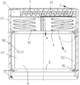
FIG. 2 is a schematic structural view of the protective structure shown in FIG. 1;
FIG. 3 is a schematic view of the internal structure of the protective frame shown in FIG. 2;
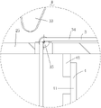
FIG. 4 is an enlarged view of the part A shown in FIG. 3;
FIG. 5 is an enlarged view of the structure of the portion B shown in FIG. 3;
FIG. 6 is an enlarged view of the structure of the portion C shown in FIG. 3;
FIG. 7 is a schematic view showing a connection structure of the storage frame and the sealing plate shown in FIG. 6;
FIG. 8 is an enlarged view of the structure of the portion D shown in FIG. 7;
fig. 9 is an enlarged view of the structure of the portion E shown in fig. 7.
In the figure: 1. unmanned aerial vehicle body, 2, protective structure, 21, the drive block, 22, the apron, 23, the protective frame, 24, the fixture block, 25, first torsion spring, 26, first pivot, 27, the guide way, 28, the baffle, 3, the roll-up structure, 31, the motor, 32, the roll-up axle, 33, the baffle, 34, the stay cord, 35, the leading wheel, 4, limit structure, 41, the locating lever, 42, the connecting block, 43, the guide axle, 5, the storage structure, 51, the guide roll, 52, the storage frame, 6, open and close the structure, 61, the closing plate, 62, the stopper, 63, the second pivot, 64, second torsion spring, 65, the third pivot, 66, the third torsion spring.
Detailed Description
In order to make the technical means, the creation characteristics, the achievement purposes and the effects of the invention easy to understand, the invention is further described with the specific embodiments.
As shown in fig. 1 to 9, the fire fighting unmanned aerial vehicle comprises an unmanned aerial vehicle body 1, a protective structure 2, a winding structure 3, a limiting structure 4, a storage structure 5 and an opening and closing structure 6; the bottom end of the unmanned aerial vehicle body 1 for providing lifting power is provided with the protective structure 2 for protecting fire extinguishing materials, and the storage structure 5 for storing the fire extinguishing materials is arranged inside the protective structure 2; the storage structure 5 is provided with the opening and closing structure 6 for sealing, and the opening and closing structure 6 is connected to the protection structure 2; the top end of the storage structure 5 is provided with the furling structure 3 for adjusting the distance between the storage structure 5 and the unmanned aerial vehicle body 1, and the furling structure 3 is fixed at the top end of the protective structure 2; the protective structure 2 is provided with a limiting structure 4 for positioning and guiding the storage structure 5, and the limiting structure 4 is fixed on the storage structure 5.
Specifically, protective structure 2 includes drive block 21, apron 22, protective frame 23, fixture block 24, first torsion spring 25, first pivot 26, guide way 27 and baffle 28, protective frame 23 locates unmanned aerial vehicle body 1's bottom, first pivot 26 through connection in apron 22 with protective frame 23, the one end of apron 22 is passed through first pivot 26 with rotate between the protective frame 23 and be connected, the other end of apron 22 is equipped with and rotates the connection drive block 21, fixture block 24 is fixed in drive block 21, just fixture block 24 with protective frame 23 block, the both ends of first torsion spring 25 are fixed in respectively apron 22 with fixture block 24, protective frame 23's bottom is equipped with four prismatic table structures guide way 27, just protective frame 23's inside is equipped with baffle 28.
Specifically, storage structure 5 includes guide roll 51 and storage frame 52, storage frame 52 locates the inside of protection frame 23, the four corners department of storage frame 52 is equipped with four and rotates the connection guide roll 51, just guide roll 51 with roll connection between the protection frame 23, the radius of guide roll 51 is greater than the axle center distance of guide roll 51 the minimum vertical distance of the side of storage frame 52.
Specifically, the furling structure 3 includes a motor 31, a furling shaft 32, a baffle 33, a pulling rope 34 and two guide wheels 35, one end of the pulling rope 34 is fixed to the storage frame 52, the pulling rope 34 is wound around the guide wheels 35, both the two guide wheels 35 are rotatably connected with the partition plate 28, one of the guide wheels 35 is arranged at a center line of the partition plate 28, the other end of the pulling rope 34 is spirally wound around the furling shaft 32, the furling shaft 32 is provided with the spiral baffle 33 for separating the pulling rope 34, one end of the furling shaft 32 is rotatably connected with the protective frame 23, the other end of the furling shaft 32 is fixed to the motor 31, and the motor 31 is fixed to the partition plate 28; the bottom end of the unmanned aerial vehicle body 1 for providing lifting power is provided with the protective structure 2 for protecting fire extinguishing materials, and the storage structure 5 for storing the fire extinguishing materials is arranged inside the protective structure 2; the top of storage structure 5 is equipped with and is used for adjusting storage structure 5 with distance between the unmanned aerial vehicle body 1 roll-up structure 3, just roll-up structure 3 is fixed in protective structure 2's top, and then be convenient for pass through roll-up structure 3 adjusts storage structure 5 with distance between the unmanned aerial vehicle body 1 makes when unmanned aerial vehicle body 1 flies, through roll-up structure 3 drives storage structure 5 is accomodate protective structure 2's inside, and then has reduced resistance and swing when flying, makes the transportation more stable high-efficient, when arriving the destination, through roll-up structure 3 drives storage structure 5 exposes to suitable position, and then the unmanned aerial vehicle of being convenient for parks in suitable high position and puts in the goods and materials, and then has improved safety in utilization greatly, promptly: when fire extinguishing materials are stored in the storage frame 52, the unmanned aerial vehicle body 1 flies to a designated position, then the motor 31 rotates, the motor 31 rotates to drive the furling shaft 32 to rotate, the length of the pull rope 34 wound on the furling shaft 32 is shortened, under the condition of the self weight of the storage frame 52 and the fire extinguishing materials, the storage frame 52 is pulled by gravity to move away from the direction of the protective frame 23, the guide roller 51 on the storage frame 52 rolls with the protective frame 23, the storage frame 52 can move more flexibly and stably in the protective frame 23, meanwhile, the guide roller 51 can guide the storage frame 52 when contacting with foreign matters, the storage frame 52 is prevented from being damaged, and when the storage frame 52 falls, the pull rope 34 drives the guide wheel 35 and the partition plate 28 to roll, thereby facilitating the guiding and limiting of the pulling rope 34, effectively preventing the pulling rope 34 from being damaged and deviating, facilitating the storage frame 52 to reach a proper height, after the material taking is finished, the motor 31 rotates reversely, the motor 31 rotates to drive the winding shaft 32 to rotate, so that the winding shaft 32 winds and winds the pulling rope 34, the baffle 33 is spirally arranged to effectively prevent the pulling rope 34 from knotting on the winding roller 32, further improving the stability, the pulling rope 34 drives the storage frame 52 to move towards the direction of the protection frame 23, when the guide roller 51 contacts with the guide groove 27, the guide groove 27 is of a four-prism-table structure, further facilitating the storage frame 52 to be guided and stored in the protection frame 23, the guide roller 51 on the storage frame 52 rolls with the protection frame 23, and further enabling the storage frame 52 to move more flexibly and stably in the protection frame 23, make storage frame 52 accomodate the inside of protective frame 23, and then effectively prevent that wind-force from causing storage structure 5 rocks the influence the effect of the flight of unmanned aerial vehicle body 1 is convenient for simultaneously unmanned aerial vehicle body 1 parks to suitable position in the high altitude.
Specifically, the limiting structure 4 includes positioning rods 41, connecting blocks 42 and guiding shafts 43, four corresponding connecting blocks 42 are arranged in a rectangular array at opposite ends of the partition plate 28 and the storage frame 52, a plurality of positioning rods 41 are arranged between the partition plate 28 and two connecting blocks 42 at opposite ends of the storage frame 52, the positioning rods 41 are rotatably connected with the connecting blocks 42 through the guiding shafts 43, the guiding shafts 43 penetrate through opposite ends of two adjacent positioning rods 41, opposite ends of two adjacent positioning rods 41 are rotatably connected through the guiding shafts 43, two adjacent positioning rods 41 are in a "V" shape, and three adjacent positioning rods 41 are in an "N" shape; be equipped with on protective structure 2 and be used for right storage structure 5 advances line location direction limit structure 4, just limit structure 4 is fixed in storage structure 5, limit structure 4 set up be convenient for right storage structure 5 carries on spacingly, prevents effectively roll-up structure 3 is adjusting storage structure 5 with during the distance between the unmanned aerial vehicle body 1 storage structure 5 rocks, has reduced the influence to wind-force, makes simultaneously storage structure 5's height's regulation is more stable, promptly: when the distance between the unmanned aerial vehicle body 1 and the storage frame 52 is increased, two adjacent positioning rods 41 rotate around the guide shaft 43, the positioning rods 41 rotate with the connecting blocks 42, the included angle between the two adjacent positioning rods 41 is increased, four connecting blocks 42 correspondingly arranged are arranged in a rectangular array at opposite ends of the partition plate 28 and the storage frame 52, a plurality of positioning rods 41 are arranged between the two connecting blocks 42 at opposite ends of the partition plate 28 and the storage frame 52, so that the storage frame 52 is effectively prevented from swinging in the horizontal direction, the influence on wind power is reduced, the height of the storage frame 52 is more stably adjusted, when the storage frame 52 is stored, the two adjacent positioning rods 41 rotate around the guide shaft 43, and the positioning rods 41 and the connecting blocks 42 rotate, the included angle between two adjacent locating rods 41 is reduced, so that the locating rods 41 are folded and stored in the protective frame 23, and the space utilization efficiency is improved.
Specifically, the opening and closing structure 6 includes a sealing plate 61, a limiting block 62, a second rotating shaft 63, a second torsion spring 64, a third rotating shaft 65 and a third torsion spring 66, the second rotating shaft 63 is connected to the sealing plate 61 and the storage frame 52 in a penetrating manner, the sealing plate 61 is connected to the storage frame 52 in a rotating manner through the second rotating shaft 63, two ends of the second torsion spring 64 are respectively fixed to the sealing plate 61 and the storage frame 52, the third rotating shaft 65 is connected to the other end of the sealing plate 61 and the limiting block 62 in a penetrating manner, the limiting block 62 with an L-shaped cross section is connected to the third rotating shaft 65 in a rotating manner, two ends of the third torsion spring 66 are respectively fixed to the third rotating shaft 65 and the limiting block 62, and the limiting block 62 is engaged with the cover plate 22; the storage structure 5 is provided with the opening and closing structure 6 for sealing, and the opening and closing structure 6 is connected to the protective structure 2, so that the opening and closing of the storage structure 5 can be controlled by controlling the opening and closing structure 6 through the protective structure 2, the material in the storage structure 5 can be taken more conveniently and quickly, and meanwhile, the unmanned aerial vehicle body 1 can conveniently add the material in the storage structure 5 in high altitude, and the operation flexibility is greatly improved; namely: when the unmanned aerial vehicle body 1 lands on the ground, the driving block 21 is pressed, the driving block 21 drives the fixture block 24 to rotate, the fixture block 24 drives the first torsion spring 25 to deform, the fixture block 24 is not clamped with the protective frame 23, then the driving block 21 is pulled, the driving block 21 pulls the cover plate 22 and the first rotating shaft 26 to rotate, the cover plate 22 drives the limiting block 62, the limiting block 62 and the cover plate 22 slide and simultaneously drive the limiting block 62 and the third rotating shaft 65 to rotate, the third torsion spring 66 deforms, and then the position of the limiting block 62 is adjusted, so that the limiting block 62 pulls the sealing plate 61 to rotate around the second rotating shaft 63 through the third rotating shaft 65, the sealing plate 61 can be driven to rotate while the cover plate 22 rotates, and opening and closing of the sealing plate are controlled simultaneously, make taking of goods and materials of putting out a fire convenient and fast more, make simultaneously more stable during the flight of unmanned aerial vehicle body 1, the setting of second torsion spring 64 is convenient for realize the automatic airtight of closing plate 61 is convenient for simultaneously pass through closing plate 61 drives stopper 62 makes stopper 62 drives apron 22 realizes the automatic of apron 22 is opened and close, works as simultaneously when unmanned aerial vehicle body 1 is in the air stagnation, works as when storage frame 52 is close to the ground, can pull closing plate 61, closing plate 61 winds second pivot 63 rotates, has avoided unmanned aerial vehicle body 1 seeks the stop point, makes the storage of goods and materials of putting out a fire more swift.
When the invention is used, when fire extinguishing materials are stored in the storage frame 52, the unmanned aerial vehicle body 1 flies to a designated position, then the motor 31 rotates, the motor 31 rotates to drive the winding shaft 32 to rotate, the length of the pull rope 34 wound on the winding shaft 32 is shortened, under the condition of the self weight of the storage frame 52 and the fire extinguishing materials, the storage frame 52 is pulled by gravity to move away from the direction of the protective frame 23, the guide roller 51 on the storage frame 52 rolls with the protective frame 23, so that the storage frame 52 can move more flexibly and stably in the protective frame 23, meanwhile, the storage frame 52 is conveniently guided when the guide roller 51 touches foreign matters, the storage frame 52 is prevented from being damaged, when the storage frame 52 falls, the pull rope 34 drives the guide wheel 35 to roll with the partition plate 28, so that the pull rope 34 is conveniently guided and limited, the damage and the deviation of the pull rope 34 are effectively prevented, and the storage frame 52 is conveniently enabled to reach a proper height, when the distance between the unmanned aerial vehicle body 1 and the storage frame 52 is increased, two adjacent positioning rods 41 rotate around the guide shaft 43, the positioning rods 41 and the connecting blocks 42 rotate, the included angle between the two adjacent positioning rods 41 is increased, four connecting blocks 42 correspondingly arranged are arranged in a rectangular array at opposite ends of the partition plate 28 and the storage frame 52, a plurality of positioning rods 41 are arranged between the partition plate 28 and the two connecting blocks 42 at opposite ends of the storage frame 52, so that the storage frame 52 is effectively prevented from swinging in the horizontal direction, the influence on wind power is reduced, the height of the storage frame 52 is more stably adjusted, after the goods and materials are taken, the motor 31 reversely rotates, the motor 31 rotates to drive the furling shaft 32 to rotate, the furling rope 34 wound by the furling shaft 32 is wound, the baffle 33 is spirally arranged to effectively prevent the furling rope 34 from knotting on the furling roller 32, and further improve the stability, the pull rope 34 drives the storage frame 52 to move towards the direction of the protective frame 23, when the guide roller 51 is in contact with the guide groove 27, the guide groove 27 is of a quadrangular frustum pyramid structure, so that the storage frame 52 can be conveniently guided and stored in the protective frame 23, the guide roller 51 on the storage frame 52 rolls with the protective frame 23, the storage frame 52 can move in the protective frame 23 more flexibly and stably, the storage frame 52 can be stored in the protective frame 23, the effect that the storage structure 5 is shaken by wind power to influence the flight of the unmanned aerial vehicle body 1 is effectively prevented, and meanwhile the unmanned aerial vehicle body 1 can be conveniently parked to a proper position in the high altitude; when the storage frame 52 is stored, the two adjacent positioning rods 41 rotate around the guide shaft 43, meanwhile, the positioning rods 41 rotate with the connecting block 42, and the included angle between the two adjacent positioning rods 41 is reduced, so that the positioning rods 41 are folded and stored in the protective frame 23, and further the space utilization efficiency is improved; when the unmanned aerial vehicle body 1 lands on the ground, the driving block 21 is pressed, the driving block 21 drives the clamping block 24 to rotate, the clamping block 24 drives the first torsion spring 25 to deform, the clamping block 24 is not clamped with the protective frame 23, then the driving block 21 is pulled, the driving block 21 pulls the cover plate 22 to rotate with the first rotating shaft 26, the cover plate 22 drives the limiting block 62, the limiting block 62 slides with the cover plate 22 and drives the limiting block 62 and the third rotating shaft 65 to rotate, the third torsion spring 66 deforms, and then the position of the limiting block 62 is adjusted, the limiting block 62 pulls the sealing plate 61 to rotate around the second rotating shaft 63 through the third rotating shaft 65, the sealing plate 61 can be driven to rotate while the cover plate 22 rotates, opening and closing are controlled conveniently and simultaneously, taking of fire extinguishing materials is more convenient and rapid, the unmanned aerial vehicle body 1 is more stable in flying, the second torsion spring 64 is convenient for realizing automatic sealing of the sealing plate 61, be convenient for simultaneously drive stopper 62 through closing plate 61, make stopper 62 drive apron 22, realize opening and close of the automation of apron 22, simultaneously when unmanned aerial vehicle body 1 is at the air stagnation, when storage frame 52 is close to the ground, can pull closing plate 61, closing plate 61 rotates around second pivot 63, has avoided unmanned aerial vehicle body 1 to seek the stop, makes the storage of the goods and materials of putting out a fire more swift.
It will be evident to those skilled in the art that the invention is not limited to the details of the foregoing illustrative embodiments, and that the present invention may be embodied in other specific forms without departing from the spirit or essential attributes thereof. The present embodiments are therefore to be considered in all respects as illustrative and not restrictive, the scope of the invention being indicated by the appended claims rather than by the foregoing description, and all changes which come within the meaning and range of equivalency of the claims are therefore intended to be embraced therein. Any reference sign in a claim should not be construed as limiting the claim concerned.
Furthermore, it should be understood that although the present description refers to embodiments, not every embodiment may contain only a single embodiment, and such description is for clarity only, and those skilled in the art should integrate the description, and the embodiments may be combined as appropriate to form other embodiments understood by those skilled in the art.
Claims (1)
1. A fire-fighting unmanned aerial vehicle is characterized by comprising an unmanned aerial vehicle body (1), a protective structure (2), a winding structure (3), a limiting structure (4), a storage structure (5) and an opening and closing structure (6); the bottom end of the unmanned aerial vehicle body (1) used for providing lifting power is provided with the protective structure (2) used for protecting fire extinguishing materials, and the storage structure (5) used for storing the fire extinguishing materials is arranged inside the protective structure (2); the storage structure (5) is provided with the opening and closing structure (6) for sealing, and the opening and closing structure (6) is connected to the protection structure (2); the top end of the storage structure (5) is provided with the furling structure (3) used for adjusting the distance between the storage structure (5) and the unmanned aerial vehicle body (1), and the furling structure (3) is fixed at the top end of the protective structure (2); the protective structure (2) is provided with the limiting structure (4) for positioning and guiding the storage structure (5), and the limiting structure (4) is fixed on the storage structure (5);
The protection structure (2) comprises a driving block (21), a cover plate (22), a protection frame (23), a clamping block (24), a first torsion spring (25), a first rotating shaft (26), a guide groove (27) and a partition plate (28), the protection frame (23) is arranged at the bottom end of the unmanned aerial vehicle body (1), the first rotating shaft (26) is connected with the cover plate (22) and the protection frame (23) in a penetrating manner, one end of the cover plate (22) is connected with the protection frame (23) in a rotating manner through the first rotating shaft (26), the other end of the cover plate (22) is provided with the driving block (21) which is connected in a rotating manner, the clamping block (24) is fixed on the driving block (21), the clamping block (24) is clamped with the protection frame (23), two ends of the first torsion spring (25) are respectively fixed on the cover plate (22) and the clamping block (24), the bottom end of the protection frame (23) is provided with the guide groove (27) with a quadrangular frustum pyramid structure, and the partition plate (28) is arranged inside the protection frame (23);
the storage structure (5) comprises guide rollers (51) and a storage frame (52), the storage frame (52) is arranged inside the protective frame (23), four corners of the storage frame (52) are provided with the four guide rollers (51) which are rotatably connected, the guide rollers (51) are in rolling connection with the protective frame (23), and the radius of each guide roller (51) is greater than the minimum vertical distance from the axis of each guide roller (51) to the side edge of the storage frame (52);
The furling structure (3) comprises a motor (31), a furling shaft (32), a baffle plate (33), a pull rope (34) and two guide wheels (35), one end of the pull rope (34) is fixed on the storage frame (52), the pull rope (34) is wound on the guide wheels (35), the two guide wheels (35) are rotatably connected with the clapboard (28), one of the guide wheels (35) is arranged at the middle line of the clapboard (28), the other end of the pull rope (34) is spirally wound on the furling shaft (32), the furling shaft (32) is provided with a spiral baffle (33) for separating the pull rope (34), one end of the furling shaft (32) is rotationally connected with the protective frame (23), the other end of the furling shaft (32) is fixed on the motor (31), and the motor (31) is fixed on the clapboard (28);
the limiting structure (4) comprises a positioning rod (41), a connecting block (42) and a guide shaft (43), the opposite ends of the partition plate (28) and the storage frame (52) are respectively provided with four corresponding connecting blocks (42) in a rectangular array, a plurality of positioning rods (41) are arranged between the partition plate (28) and the two connecting blocks (42) at the opposite ends of the storage frame (52), the positioning rods (41) are rotatably connected with the connecting block (42) through the guide shafts (43), the guide shafts (43) penetrate through the opposite ends of two adjacent positioning rods (41), the opposite ends of two adjacent positioning rods (41) are rotatably connected through the guide shafts (43), two adjacent positioning rods (41) are V-shaped, and three adjacent positioning rods (41) are N-shaped;
The opening and closing structure (6) comprises a sealing plate (61), a limiting block (62), a second rotating shaft (63), a second torsion spring (64), a third rotating shaft (65) and a third torsion spring (66), the second rotating shaft (63) is connected with the sealing plate (61) and the storage frame (52) in a penetrating manner, the sealing plate (61) is connected with the storage frame (52) in a rotating manner through the second rotating shaft (63), two ends of the second torsion spring (64) are respectively fixed on the sealing plate (61) and the storage frame (52), the third rotating shaft (65) is connected with the other end of the sealing plate (61) and the limiting block (62) in a penetrating manner, the limiting block (62) with an L-shaped section is connected with the third rotating shaft (65) in a rotating manner, two ends of the third torsion spring (66) are respectively fixed on the third rotating shaft (65) and the limiting block (62), the limiting block (62) is clamped with the cover plate (22).
Priority Applications (1)
| Application Number | Priority Date | Filing Date | Title |
|---|---|---|---|
| CN202011631623.0A CN112644698B (en) | 2020-12-31 | 2020-12-31 | Fire control is with unmanned aerial vehicle that puts out a fire |
Applications Claiming Priority (1)
| Application Number | Priority Date | Filing Date | Title |
|---|---|---|---|
| CN202011631623.0A CN112644698B (en) | 2020-12-31 | 2020-12-31 | Fire control is with unmanned aerial vehicle that puts out a fire |
Publications (2)
| Publication Number | Publication Date |
|---|---|
| CN112644698A CN112644698A (en) | 2021-04-13 |
| CN112644698B true CN112644698B (en) | 2022-05-24 |
Family
ID=75366783
Family Applications (1)
| Application Number | Title | Priority Date | Filing Date |
|---|---|---|---|
| CN202011631623.0A Active CN112644698B (en) | 2020-12-31 | 2020-12-31 | Fire control is with unmanned aerial vehicle that puts out a fire |
Country Status (1)
| Country | Link |
|---|---|
| CN (1) | CN112644698B (en) |
Families Citing this family (1)
| Publication number | Priority date | Publication date | Assignee | Title |
|---|---|---|---|---|
| CN113117278B (en) * | 2021-04-26 | 2021-12-07 | 北京中海兴达建设有限公司 | Remote detection mechanical equipment based on artificial intelligence |
Citations (5)
| Publication number | Priority date | Publication date | Assignee | Title |
|---|---|---|---|---|
| CN106081112A (en) * | 2016-07-12 | 2016-11-09 | 于卫华 | Unmanned vehicle intelligence acceptance goods device and implementation |
| US9688404B1 (en) * | 2014-12-02 | 2017-06-27 | Amazon Technologies, Inc. | Stabilized airborne drop delivery |
| CN109018364A (en) * | 2018-09-29 | 2018-12-18 | 拓攻(南京)机器人有限公司 | A kind of box for material circulation and the logistics unmanned plane containing it |
| CN209112444U (en) * | 2018-09-13 | 2019-07-16 | 南昌理工学院 | Loading unmanned plane |
| CN111152927A (en) * | 2020-02-12 | 2020-05-15 | 哈瓦国际航空技术(深圳)有限公司 | Put in cloud platform and unmanned aerial vehicle |
Family Cites Families (1)
| Publication number | Priority date | Publication date | Assignee | Title |
|---|---|---|---|---|
| US10773930B2 (en) * | 2016-07-27 | 2020-09-15 | Jeong-Hoon SHIN | Home-delivered article loading device for drone |
-
2020
- 2020-12-31 CN CN202011631623.0A patent/CN112644698B/en active Active
Patent Citations (5)
| Publication number | Priority date | Publication date | Assignee | Title |
|---|---|---|---|---|
| US9688404B1 (en) * | 2014-12-02 | 2017-06-27 | Amazon Technologies, Inc. | Stabilized airborne drop delivery |
| CN106081112A (en) * | 2016-07-12 | 2016-11-09 | 于卫华 | Unmanned vehicle intelligence acceptance goods device and implementation |
| CN209112444U (en) * | 2018-09-13 | 2019-07-16 | 南昌理工学院 | Loading unmanned plane |
| CN109018364A (en) * | 2018-09-29 | 2018-12-18 | 拓攻(南京)机器人有限公司 | A kind of box for material circulation and the logistics unmanned plane containing it |
| CN111152927A (en) * | 2020-02-12 | 2020-05-15 | 哈瓦国际航空技术(深圳)有限公司 | Put in cloud platform and unmanned aerial vehicle |
Also Published As
| Publication number | Publication date |
|---|---|
| CN112644698A (en) | 2021-04-13 |
Similar Documents
| Publication | Publication Date | Title |
|---|---|---|
| JP5908989B2 (en) | 凧 Ground station and system using it | |
| US5497962A (en) | Mooring tower assembly for a lighter-than-air vehicle | |
| EP3770066B1 (en) | Drone for low-noise delivery of objects | |
| DE102016224479A1 (en) | Transport drone for people | |
| US20240228037A1 (en) | Flight vehicle with mounting unit having moving means, and mouning unit | |
| US20110127378A1 (en) | Launch and recovery system for unmanned aerial vehicles | |
| HK1000556B (en) | A mooring tower assembly for a lighter-than-air vehicle | |
| WO1998034823A1 (en) | Aerial cableway leading to an aerostatic airborne body | |
| DE60010435T2 (en) | STARTING PROCEDURE FOR HIGH-FLYING AIR SHIPS | |
| WO2024146907A1 (en) | Wind energy system for generating power | |
| JP6811508B1 (en) | Landing equipment | |
| CN115177890A (en) | Fire hose laying mechanism and method | |
| CN112644698A (en) | Fire control is with unmanned aerial vehicle that puts out a fire | |
| EP4178857A1 (en) | Hybrid drone for landing on vertical structures | |
| JP6928991B1 (en) | Landing equipment | |
| DE102015008900A1 (en) | Modular airship | |
| CN220555384U (en) | Many rotor unmanned aerial vehicle goods carry-on mechanism | |
| CN210782261U (en) | Canopy is planted to fruit vegetables | |
| EP3276163B1 (en) | Device for generating electric power using a high wind turbine | |
| DE102017004420A1 (en) | Method for operating an unmanned, wired fixed-wing aircraft | |
| CN114987787B (en) | Wired system type unmanned aerial vehicle high-altitude base station and use method | |
| CN120589211B (en) | A paraglider towing drone | |
| CN222247774U (en) | Tethered unmanned aerial vehicle fire control mobile carrier | |
| CN117657510A (en) | A tethered UAV fire-fighting mobile carrier and its use method | |
| CN107499528B (en) | A kind of unmanned plane water surface parking device |
Legal Events
| Date | Code | Title | Description |
|---|---|---|---|
| PB01 | Publication | ||
| PB01 | Publication | ||
| SE01 | Entry into force of request for substantive examination | ||
| SE01 | Entry into force of request for substantive examination | ||
| GR01 | Patent grant | ||
| GR01 | Patent grant |