CN112643438A - Plastic pipe mouth of pipe grinding device - Google Patents
Plastic pipe mouth of pipe grinding device Download PDFInfo
- Publication number
- CN112643438A CN112643438A CN202110056278.0A CN202110056278A CN112643438A CN 112643438 A CN112643438 A CN 112643438A CN 202110056278 A CN202110056278 A CN 202110056278A CN 112643438 A CN112643438 A CN 112643438A
- Authority
- CN
- China
- Prior art keywords
- chamber
- polishing
- feeding
- cavity
- clamp
- Prior art date
- Legal status (The legal status is an assumption and is not a legal conclusion. Google has not performed a legal analysis and makes no representation as to the accuracy of the status listed.)
- Withdrawn
Links
Images




Classifications
-
- B—PERFORMING OPERATIONS; TRANSPORTING
- B24—GRINDING; POLISHING
- B24B—MACHINES, DEVICES, OR PROCESSES FOR GRINDING OR POLISHING; DRESSING OR CONDITIONING OF ABRADING SURFACES; FEEDING OF GRINDING, POLISHING, OR LAPPING AGENTS
- B24B9/00—Machines or devices designed for grinding edges or bevels on work or for removing burrs; Accessories therefor
- B24B9/007—Machines or devices designed for grinding edges or bevels on work or for removing burrs; Accessories therefor for end faces of tubes
-
- B—PERFORMING OPERATIONS; TRANSPORTING
- B24—GRINDING; POLISHING
- B24B—MACHINES, DEVICES, OR PROCESSES FOR GRINDING OR POLISHING; DRESSING OR CONDITIONING OF ABRADING SURFACES; FEEDING OF GRINDING, POLISHING, OR LAPPING AGENTS
- B24B41/00—Component parts such as frames, beds, carriages, headstocks
- B24B41/005—Feeding or manipulating devices specially adapted to grinding machines
-
- B—PERFORMING OPERATIONS; TRANSPORTING
- B24—GRINDING; POLISHING
- B24B—MACHINES, DEVICES, OR PROCESSES FOR GRINDING OR POLISHING; DRESSING OR CONDITIONING OF ABRADING SURFACES; FEEDING OF GRINDING, POLISHING, OR LAPPING AGENTS
- B24B41/00—Component parts such as frames, beds, carriages, headstocks
- B24B41/06—Work supports, e.g. adjustable steadies
- B24B41/067—Work supports, e.g. adjustable steadies radially supporting workpieces
-
- B—PERFORMING OPERATIONS; TRANSPORTING
- B24—GRINDING; POLISHING
- B24B—MACHINES, DEVICES, OR PROCESSES FOR GRINDING OR POLISHING; DRESSING OR CONDITIONING OF ABRADING SURFACES; FEEDING OF GRINDING, POLISHING, OR LAPPING AGENTS
- B24B47/00—Drives or gearings; Equipment therefor
-
- B—PERFORMING OPERATIONS; TRANSPORTING
- B24—GRINDING; POLISHING
- B24B—MACHINES, DEVICES, OR PROCESSES FOR GRINDING OR POLISHING; DRESSING OR CONDITIONING OF ABRADING SURFACES; FEEDING OF GRINDING, POLISHING, OR LAPPING AGENTS
- B24B47/00—Drives or gearings; Equipment therefor
- B24B47/10—Drives or gearings; Equipment therefor for rotating or reciprocating working-spindles carrying grinding wheels or workpieces
- B24B47/12—Drives or gearings; Equipment therefor for rotating or reciprocating working-spindles carrying grinding wheels or workpieces by mechanical gearing or electric power
-
- B—PERFORMING OPERATIONS; TRANSPORTING
- B24—GRINDING; POLISHING
- B24B—MACHINES, DEVICES, OR PROCESSES FOR GRINDING OR POLISHING; DRESSING OR CONDITIONING OF ABRADING SURFACES; FEEDING OF GRINDING, POLISHING, OR LAPPING AGENTS
- B24B47/00—Drives or gearings; Equipment therefor
- B24B47/20—Drives or gearings; Equipment therefor relating to feed movement
-
- B—PERFORMING OPERATIONS; TRANSPORTING
- B24—GRINDING; POLISHING
- B24B—MACHINES, DEVICES, OR PROCESSES FOR GRINDING OR POLISHING; DRESSING OR CONDITIONING OF ABRADING SURFACES; FEEDING OF GRINDING, POLISHING, OR LAPPING AGENTS
- B24B47/00—Drives or gearings; Equipment therefor
- B24B47/22—Equipment for exact control of the position of the grinding tool or work at the start of the grinding operation
Landscapes
- Engineering & Computer Science (AREA)
- Mechanical Engineering (AREA)
- Finish Polishing, Edge Sharpening, And Grinding By Specific Grinding Devices (AREA)
Abstract
The invention discloses a plastic pipe orifice polishing device which comprises a main body, wherein a polishing cavity is arranged in the main body, a clamp assembly is arranged in the polishing cavity, a driving cavity with the right side extending upwards is arranged on the lower side of the polishing cavity, a clamp rotating shaft extending upwards to the polishing cavity is rotatably arranged on the upper end wall of the driving cavity, a discharging rotating shaft connected with the clamp rotating shaft through a torsional spring is rotatably arranged on the upper side of the clamp rotating shaft, a clamp rotating block is fixedly arranged on the discharging rotating shaft, a plastic pipe to be polished is placed in the device, the clamp clamps the plastic pipe under the action of gravity when the plastic pipe falls onto the clamp, the polishing block polishes the plastic pipe orifice along an arc-shaped track motion, an electromagnet is electrified after polishing is completed, the clamp inclines and loosens the plastic pipe, and the plastic pipe falls into a discharge port and simultaneously drives a feed cylinder.
Description
Technical Field
The invention relates to the technical field of plastics, in particular to a plastic pipe orifice polishing device.
Background
The plastic pipe is generally made by using synthetic resin, i.e. polyester, as raw material, adding stabilizer, lubricant, plasticizer, etc. and then extruding the mixture in a pipe making machine by a "plastic" method. The pipe is mainly used as a tap water supply system pipe, a drainage, exhaust and pollution discharge sanitary pipe, an underground drainage pipe system, a rainwater pipe, a threading pipe for electric wire installation and assembly, and the like. The plastic pipe can cut according to required length when using, but the mouth of pipe cross-section is comparatively sharp after the plastic pipe cuts, and easy fish tail skin has certain danger during the use.
Disclosure of Invention
Aiming at the technical defects, the invention provides a plastic pipe orifice polishing device which can overcome the defects.
The invention discloses a plastic pipe orifice polishing device which comprises a main body, wherein a polishing cavity is arranged in the main body, a clamp assembly is arranged in the polishing cavity, a driving cavity with the right side extending upwards is arranged at the lower side of the polishing cavity, a clamp rotating shaft extending upwards to the polishing cavity is rotatably arranged on the upper end wall of the driving cavity, a blanking rotating shaft connected with the clamp rotating shaft through a torsion spring is rotatably arranged at the upper side of the clamp rotating shaft, a clamp rotating block is fixedly arranged on the blanking rotating shaft, a clamp box is fixedly arranged at the upper side of the clamp rotating block, a clamp block sliding groove with the upper side communicated with the polishing cavity is arranged in the clamp box, clamping blocks connected with the clamp block sliding groove through clamping block springs are symmetrically arranged in the clamp block sliding groove in a front-back sliding mode, a gravity lifting groove is communicated with the lower side of the clamping block sliding groove through an inclined plane in a sliding fit mode, and a gravity spring is arranged in the gravity lifting groove in a The gravity lift piece of connection, it is equipped with the rotation chamber to polish chamber right side intercommunication, it is equipped with the subassembly of polishing to rotate the intracavity, it installs to rotate chamber right-hand member wall and extends right to drive the drive shaft in chamber, drive shaft left side fixed mounting has the rotation case of polishing, it is equipped with the left side and the communicating slip chamber of polishing in external world to polish to rotate the incasement, it has the arc track to polish slip chamber front and back end wall fixed mounting, slidable mounting has the sliding block of polishing on the arc track, the sliding block left side of polishing is equipped with the first flexible groove of polishing, first polish in the flexible inslot slide be equipped with the first flexible piece of polishing that flexible spring connects of polishing, it is equipped with the slide bar of polishing to polish slide chamber right side end wall from top to bottom, the slide bar left side of polishing is equipped with the second flexible groove of polishing, second polish in the flexible inslot slide be equipped with the second The left side with the slider right side articulated telescopic link of polishing, the chamber upside intercommunication of polishing is equipped with the feeding and rotates the chamber, the feeding rotates the intracavity and is equipped with the feeding subassembly.
Preferably, the fixture assembly further comprises a connecting rod rotating cavity located on the lower side of the gravity lifting groove, the left and right sides of the connecting rod rotating cavity are symmetrically communicated and provided with a resetting sliding groove, the resetting sliding groove is far away from the connecting rod rotating cavity side and provided with a supporting block sliding groove, the lower end wall of the connecting rod rotating cavity is rotatably provided with a connecting rod rotating shaft, a first connecting rod is fixedly installed on the connecting rod rotating shaft, a resetting sliding block connected with the resetting sliding groove through a resetting spring is arranged in the resetting sliding groove in a sliding manner, the resetting sliding block is fixedly installed on the side close to the connecting rod rotating shaft, the other end of the second connecting rod is hinged with a third connecting rod, the other end of the third connecting rod is hinged with the first connecting rod, a first positive magnet is fixedly installed on the upper side of the resetting sliding block, and a second positive magnet capable of repelling with the first positive magnet is fixedly, the repulsive force between the second positive magnet and the first positive magnet is larger than the elastic force of the gravity spring, the lower end wall of the polishing cavity is fixedly installed with an electromagnet which is located on the right side of the clamp rotating shaft and can be matched with the abutting block in a sliding groove, the lower end wall of the polishing cavity is fixedly installed with an abutting block which is located on the left side of the clamp rotating shaft, and iron blocks which are matched with the electromagnet are symmetrically and fixedly installed at the left end and the right end of the lower side of the clamp box.
Preferably, the subassembly of polishing still include with polish sliding chamber right side intercommunication be equipped with and with rotate the communicating cam rotation chamber in chamber, the cam rotates the chamber under the terminal wall and rotates and install the cam axis of rotation, fixed mounting has the space cam who contains the spacing groove in the cam axis of rotation, polish slide bar right side fixed mounting have with spacing groove sliding fit's stopper, the cam rotates chamber right-hand member wall and rotates and install the transmission shaft of polishing, polish the transmission shaft with the cam axis of rotation is located the cam rotates the chamber and connects through a set of bevel gear pair transmission, fixed mounting has the gear of polishing on the transmission shaft of polishing, rotate intracavity side terminal wall fixed mounting have can with gear engagement's internal tooth gear polishes, be equipped with drive assembly in the drive chamber.
Preferably, the transmission assembly include with drive chamber right-hand member wall fixed mounting and with the motor that drive shaft power is connected, drive chamber right-hand member wall rotates and installs first anchor clamps transmission shaft, drive chamber upper end wall rotates and installs and is located the second anchor clamps transmission shaft on anchor clamps axis of rotation right side, fixed mounting has the sheave in the anchor clamps axis of rotation, fixed mounting has the thumb wheel on the second anchor clamps transmission shaft, second anchor clamps transmission shaft with first anchor clamps transmission shaft is located the drive chamber is connected through a set of bevel gear pair transmission, first anchor clamps transmission shaft with the drive shaft is located the drive chamber is connected through a set of belt pulley transmission.
Preferably, the feeding subassembly include with the feeding rotates the feeding chamber that chamber upside intercommunication was equipped with, the feeding rotates the chamber left side and is equipped with feeding transmission chamber, the feeding rotates chamber left end wall and rotates and install and extend to left the feeding axis of rotation in feeding transmission chamber, the feeding rotate the intracavity be equipped with feeding axis of rotation fixed mounting's the equal angle feed cylinder that contains six plastic pipe grooves, the feeding transmission intracavity be equipped with feeding axis of rotation fixed mounting's ratchet, feeding transmission chamber left end wall rotates installs hollow axis of rotation, fixed mounting has the cover in the hollow axis of rotation the hollow gear in the ratchet outside, hollow gear inboard equal angle hinge have two with hollow gear passes through pawl spring coupling.
Preferably, the feeding subassembly still include with the rack sliding tray that feeding transmission chamber downside intercommunication was equipped with, it is equipped with the discharge gate to polish chamber downside intercommunication, discharge gate left side intercommunication be equipped with the upside with the lever of rack sliding tray intercommunication rotates the chamber, the lever rotate the chamber rear end wall rotate install with the lever rotates the lever axis of rotation that the chamber front end wall passes through torsional spring connection, fixed mounting has the lever in the lever axis of rotation, slide in the rack sliding tray be equipped with the downside with lever upside contact and with the lever rotate the chamber upper end wall through rack spring connection can with the rack of ratchet rear side meshing.
The beneficial effects are that: the device simple structure, convenient operation, the device is at the during operation, the plastic pipe that will treat to polish is put into the device, because the clamp of action of gravity presss from both sides tight plastic pipe when the plastic pipe falls into on the anchor clamps, the plastic pipe mouth of pipe is polished along arc orbital motion to the polishing block, rotate a week around the plastic pipe centre of a circle simultaneously, polish and accomplish the back electro-magnet circular telegram, the plastic pipe is loosened in anchor clamps slope, the plastic pipe falls into and drives feed cylinder rotation feeding simultaneously in the discharge gate, prevent that the plastic pipe mouth of pipe cross-section is too sharp fish tail user's skin.
Drawings
In order to more clearly illustrate the embodiments of the invention or the technical solutions in the prior art, the drawings used in the description of the embodiments or the prior art will be briefly described below, and it is obvious that the drawings in the following description are only some embodiments of the invention, and it is obvious for those skilled in the art that other drawings can be obtained based on these drawings without creative efforts.
FIG. 1 is a schematic structural diagram of an embodiment of the present invention;
FIG. 2 is a schematic diagram of the structure A-A of FIG. 1 according to an embodiment of the present invention;
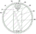
FIG. 3 is a schematic diagram of the structure B-B in FIG. 1 according to an embodiment of the present invention;
FIG. 4 is an enlarged schematic view of the structure at C in FIG. 1 according to an embodiment of the present invention;
FIG. 5 is an enlarged schematic view of the structure at D in FIG. 1 according to an embodiment of the present invention;
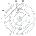
FIG. 6 is a schematic diagram of the structure E-E in FIG. 4 according to an embodiment of the present invention;
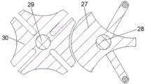
FIG. 7 is a schematic diagram of the structure F-F in FIG. 1 according to an embodiment of the present invention;
FIG. 8 is a schematic diagram of the structures G-G in FIG. 1 according to an embodiment of the present invention.
Detailed Description
All of the features disclosed in this specification, or all of the steps in any method or process so disclosed, may be combined in any combination, except combinations of features and/or steps that are mutually exclusive.
The invention will now be described in detail with reference to fig. 1-8, for the sake of convenience, the orientations described hereinafter being defined as follows: the up, down, left, right, and front-back directions described below correspond to the up, down, left, right, and front-back directions in the projection relationship of fig. 1 itself.
The invention discloses a plastic pipe orifice polishing device, which comprises a main body 10, wherein a polishing cavity 33 is arranged in the main body 10, a clamp assembly capable of clamping a plastic pipe is arranged in the polishing cavity 33, a driving cavity 31 extending upwards from the right side is arranged at the lower side of the polishing cavity 33, a clamp rotating shaft 29 extending upwards to the polishing cavity 33 is rotatably arranged on the upper end wall of the driving cavity 31, a blanking rotating shaft 79 connected with the clamp rotating shaft 29 through a torsion spring is rotatably arranged at the upper side of the clamp rotating shaft 29, a clamp rotating block 50 is fixedly arranged on the blanking rotating shaft 79, a clamp box 15 is fixedly arranged at the upper side of the clamp rotating block 50, a clamp block sliding groove 52 with the upper side communicated with the polishing cavity 33 is arranged in the clamp box 15, and clamp blocks 46 connected with the clamp block sliding groove 52 through a clamp block spring 51 are symmetrically arranged in the clamp block sliding groove 52 in a front-back sliding manner, the lower side of the clamping block sliding groove 52 is communicated with a gravity lifting groove 48, a gravity lifting block 47 which is in slide fit with the lower side of the clamping block 46 through an inclined plane and is connected with the gravity lifting groove 48 through a gravity spring 49 is arranged in the gravity lifting groove 48, the gravity lifting block 47 slides downwards due to the action of gravity when a plastic pipe falls into the clamping block sliding groove 52, the gravity spring 49 is compressed, the clamping block 46 clamps the plastic pipe due to the inward sliding action of the clamping block spring 51, the right side of the grinding cavity 33 is communicated with a rotating cavity 17, a grinding assembly for grinding the pipe orifice cross section of the plastic pipe is arranged in the rotating cavity 17, the driving shaft 23 extending rightwards to the driving cavity 31 is rotatably arranged on the wall of the right end of the rotating cavity 17, a grinding rotating box 18 is fixedly arranged on the left side of the driving shaft 23, and a grinding sliding cavity 66 which is communicated with the outside on the left, the front end wall and the rear end wall of the polishing sliding cavity 66 are fixedly provided with arc-shaped rails 76, the arc-shaped rails 76 are slidably provided with polishing sliding blocks 72, the left side of each polishing sliding block 72 is provided with a first polishing telescopic groove 75, each first polishing telescopic groove 75 is internally provided with a polishing telescopic block 74 connected with the corresponding first polishing telescopic groove 75 through a first polishing telescopic spring 73 in a sliding manner, the right end wall of the polishing sliding cavity 66 is provided with a polishing sliding rod 68 in a vertical sliding manner, the left side of the polishing sliding rod 68 is provided with a second polishing telescopic groove 71, each second polishing telescopic groove 71 is internally provided with a polishing telescopic rod 67 connected with the corresponding second polishing telescopic groove 71 through a second polishing telescopic spring 69 in a sliding manner, the left side of the polishing telescopic rod is hinged with the right side of the polishing sliding block 72, the upper side of the polishing cavity 33 is communicated with a feeding rotating cavity 12, the polishing sliding rod 68 slides up and down in the polishing sliding cavity 66 to drive the polishing sliding block 72 to slide along the arc-shaped track 76, the polishing telescopic block 74 is used for polishing the cross section of the pipe orifice of the plastic pipe, and the polishing telescopic rod 67 slides in the second polishing telescopic groove 71.
Beneficially, the fixture assembly further comprises a connecting rod rotating cavity 55 located on the lower side of the gravity lifting groove 48, the left side and the right side of the connecting rod rotating cavity 55 are symmetrically communicated with each other to form a resetting sliding groove 63, the resetting sliding groove 63 is far away from the connecting rod rotating cavity 55, the connecting rod rotating cavity 55 is communicated with each other to form a abutting sliding groove 65, a connecting rod rotating shaft 60 is rotatably mounted on the lower end wall of the connecting rod rotating cavity 55, a first connecting rod 59 is fixedly mounted on the connecting rod rotating shaft 60, a resetting sliding block 56 connected with the resetting sliding groove 63 through a resetting spring 58 is slidably mounted in the resetting sliding groove 63, the resetting sliding block 56 is close to the connecting rod rotating shaft 60, a second connecting rod 62 is fixedly mounted on the side of the connecting rod rotating shaft 60, the other end of the second connecting rod 62 is hinged to a third connecting rod 61, the other end of the second connecting rod is hinged to the first connecting rod 59, a first positive magnet A repulsive second positive magnet 54, a repulsive force between the second positive magnet 54 and the first positive magnet 57 is greater than an elastic force of the gravity spring 49, a resisting block 16 which is positioned at the right side of the clamp rotating shaft 29 and can be matched with the resisting block sliding groove 65 is fixedly installed on the lower end wall of the grinding cavity 33, an electromagnet 32 which is positioned at the left side of the clamp rotating shaft 29 is fixedly installed on the lower end wall of the grinding cavity 33, iron blocks 64 which can be matched with the electromagnet 32 are symmetrically and fixedly installed at the left and right ends of the lower side of the clamp box 15, the resisting block 16 is matched with the right resisting block sliding groove 65 when the clamp box 15 is in a horizontal state, so that the right reset sliding block 56 is pushed to slide towards the side close to the connecting rod rotating cavity 55, so that the first connecting rod 59 is driven to rotate around the connecting rod rotating shaft 60, and the left reset sliding block 56 is driven to slide towards the side close to the connecting, the reset spring 58 is compressed, the electromagnet 32 is electrified to adsorb the left iron block 64, so that the clamp box 15 and the clamp rotating block 50 are driven to rotate around the blanking rotating shaft 79, the abutting block 16 is separated from the right abutting block sliding groove 65, the reset sliding block 56 slides towards the side close to the abutting block sliding groove 65 under the action of the reset spring 58, the first positive magnet 57 and the second positive magnet 54 repel each other, the gravity lifting block 47 is pushed to slide upwards, so that the clamping block 46 is pushed to be opened to the front side and the rear side to release the plastic pipe, and the clamping block spring 51 is compressed.
Beneficially, the polishing assembly further comprises a cam rotating cavity 21 which is communicated with the right side of the polishing sliding cavity 66 and communicated with the rotating cavity 17, a cam rotating shaft 25 is installed on the lower end wall of the cam rotating cavity 21 in a rotating mode, a space cam 24 containing a limiting groove 80 is fixedly installed on the cam rotating shaft 25, a limiting block 70 in sliding fit with the limiting groove 80 is fixedly installed on the right side of the polishing sliding rod 68, a polishing transmission shaft 53 is installed on the right end wall of the cam rotating cavity 21 in a rotating mode, the polishing transmission shaft 53 and the cam rotating shaft 25 are located in the cam rotating cavity 21 and connected through a set of bevel gear pair transmission, a polishing gear 20 is fixedly installed on the polishing transmission shaft 53, an internal gear 19 which can be meshed with the polishing gear 20 is fixedly installed on the end wall of the inner side of the rotating cavity 17, and a transmission assembly is, drive shaft 23 drives when rotating the case 18 that rotates of polishing, polish gear 20 with internal tooth gear 19 meshes, thereby drives gear 20 that polishes rotates, thereby drives transmission shaft 53 that polishes rotates, thereby drives cam axis of rotation 25 rotates, thereby drives space cam 24 rotates, stopper 70 is in slide in spacing groove 80, thereby drives slide bar 68 of polishing slides in sliding chamber 66 of polishing.
Advantageously, the transmission assembly comprises a motor 22 fixedly mounted on the right end wall of the driving chamber 31 and in power connection with the driving shaft 23, a first clamp transmission shaft 26 is rotatably mounted on the right end wall of the driving chamber 31, a second clamp transmission shaft 28 is rotatably mounted on the upper end wall of the driving chamber 31 and located on the right side of the clamp rotation shaft 29, a grooved pulley 30 is fixedly mounted on the clamp rotation shaft 29, a dial wheel 27 is fixedly mounted on the second clamp transmission shaft 28, the grooved pulley 30 is shifted to rotate for half a circle when the dial wheel 27 rotates for one circle, so as to drive the clamp rotation shaft 29 to rotate for half a circle, the second clamp transmission shaft 28 and the first clamp transmission shaft 26 are located in the driving chamber 31 and are in transmission connection through a set of bevel gear pairs, the first clamp transmission shaft 26 and the driving shaft 23 are located in the driving chamber 31 and are in transmission connection through, the rotational speed of the drive shaft 23 is greater than the rotational speed of the second chuck drive shaft 28.
Beneficially, the feeding assembly includes a feeding cavity 13 communicated with the upper side of the feeding rotating cavity 12, a feeding transmission cavity 43 is arranged on the left side of the feeding rotating cavity 12, a feeding rotating shaft 11 extending leftwards to the feeding transmission cavity 43 is rotatably mounted on the left end wall of the feeding rotating cavity 12, a feeding barrel 14 which is fixedly mounted with the feeding rotating shaft 11 and contains six plastic pipe grooves 45 at equal angles is arranged in the feeding rotating cavity 12, a ratchet 41 fixedly mounted with the feeding rotating shaft 11 is arranged in the feeding transmission cavity 43, a hollow rotating shaft 42 is rotatably mounted on the left end wall of the feeding transmission cavity 43, a hollow gear 44 sleeved on the outer side of the ratchet 41 is fixedly mounted on the hollow rotating shaft 42, and two pawls 78 connected with the hollow gear 44 through pawl springs 77 are hinged on the inner side of the hollow gear 44 at equal angles.
Beneficially, the feeding assembly further comprises a rack sliding groove 39 communicated with the lower side of the feeding transmission cavity 43, the lower side of the grinding cavity 33 is communicated with the discharge hole 34, the left side of the discharge hole 34 is communicated with a lever rotating cavity 38 with the upper side communicated with the rack sliding groove 39, the rear end wall of the lever rotating cavity 38 is rotatably provided with a lever rotating shaft 35 connected with the front end wall of the lever rotating cavity 38 through a torsion spring, a lever 36 is fixedly arranged on the lever rotating shaft 35, a rack 40 which is in contact with the upper side of the lever 36 at the lower side and is connected with the upper end wall of the lever rotating cavity 38 through a rack spring 37 and can be meshed with the rear side of the ratchet wheel 41 is slidably arranged in the rack sliding groove 39, when the plastic pipe is discharged, the lever 36 is pushed to rotate around the lever rotating shaft 35, so that the rack 40 is pushed to slide upwards, and, when the rack 40 slides upwards, the hollow gear 44 does not drive the ratchet wheel 41 to rotate, when the lever 36 is reset due to the action of the torsion spring on the lever rotating shaft 35, the rack 40 slides downwards due to the action of the rack spring 37, so that the hollow gear 44 is driven to rotate, the ratchet wheel 41 is driven to rotate for one sixth of a circle, the feeding rotating shaft 11 is driven to rotate for one sixth of a circle, the feeding barrel 14 is driven to rotate for one sixth of a circle, and the plastic pipes in the plastic pipe grooves 45 at the lower side fall into the grinding cavity 33.
In an initial state, the electromagnet 32 is not powered on, the clamp box 15 is in a horizontal state, the gravity lifting block 47 is located at the uppermost side, the gravity spring 49 is in a normal stretching state, the clamping block 46 is located at the outermost side, the clamping block spring 51 is in a compressing state, the reset sliding block 56 is located at the innermost side, the reset spring 58 is in a compressing state, the abutting block 16 is located in the right abutting block sliding groove 65, the polishing sliding rod 68 is located in the middle of the polishing sliding cavity 66, the polishing sliding block 72 is located in the middle of the arc-shaped rail 76, the polishing telescopic rod 67 is located at the innermost side of the second polishing telescopic groove 71, the second polishing telescopic spring 69 is in a compressing state, the lever 36 is in a horizontal state, the rack 40 is located at the lowermost side.
When the plastic pipe works, the plastic pipe falls into the clamping block sliding groove 52, the gravity lifting block 47 slides downwards under the action of gravity, the gravity spring 49 is compressed, the clamping block 46 slides inwards under the action of the clamping block spring 51 to clamp the plastic pipe, the motor 22 is started to drive the driving shaft 23 to rotate, so as to drive the polishing rotating box 18 to rotate, the polishing gear 20 is meshed with the internal gear 19, so as to drive the polishing gear 20 to rotate, so as to drive the polishing transmission shaft 53 to rotate, so as to drive the cam rotating shaft 25 to rotate, so as to drive the space cam 24 to rotate, the limiting block 70 slides in the limiting groove 80, so as to drive the polishing sliding rod 68 to slide in the polishing sliding cavity 66, the polishing sliding block 72 slides along the arc-shaped track 76, the polishing telescopic block 74 polishes the pipe orifice section of the plastic pipe, the polishing telescopic rod 67 slides in the second polishing telescopic groove, thereby driving the second fixture transmission shaft 28 to rotate, the rotation speed of the driving shaft 23 is greater than that of the second fixture transmission shaft 28, the second fixture transmission shaft 28 drives the dial wheel 27 to rotate, the dial wheel 27 rotates for a circle, the grooved wheel 30 rotates for a half circle, thereby driving the fixture rotation shaft 29 to rotate for a half circle, the polishing expansion block 74 polishes the cross section of the plastic pipe orifice at the other end, after polishing, the motor 22 stops the electromagnet 32 to be electrified, adsorbs the left iron block 64, the fixture box 15 and the fixture rotation block 50 rotate around the blanking rotation shaft 79, the abutting block 16 is separated from the right abutting block sliding groove 65, the reset sliding block 56 slides to the side close to the abutting block sliding groove 65 under the action of the reset spring 58, the first positive magnet 57 and the second positive magnet 54 repel each other, the gravity lifting block 47 is pushed to slide upwards, thereby pushing the clamping block 46 to open to the front and back sides to release the plastic pipe, the clamping, the electromagnet 32 is powered off, the clamp box 15 and the clamp rotating block 50 rotate around the blanking rotating shaft 79 to restore the horizontal state under the action of the torsion spring on the blanking rotating shaft 79, the abutting block 16 is inserted into the right abutting block sliding groove 65, so that the right return sliding block 56 is pushed to slide towards the side close to the connecting rod rotating cavity 55, the first connecting rod 59 is driven to rotate around the connecting rod rotating shaft 60, so that the left return sliding block 56 is driven to slide towards the side close to the connecting rod rotating cavity 55, the return spring 58 is compressed, the lever 36 is pushed to rotate around the lever rotating shaft 35 when the plastic pipe falls down, so that the rack 40 is pushed to slide upwards, the rack spring 37 is compressed, the ratchet wheel 41 is not driven to rotate by the space-time gear 44 when the rack 40 slides upwards, the rack 40 slides downwards under the action of the rack spring 37 when the lever 36 is reset under the action of the torsion spring, thereby driving the feeding rotating shaft 11 to rotate for one sixth of a circle, and thus driving the feeding cylinder 14 to rotate for one sixth of a circle, and the plastic pipe in the lower plastic pipe groove 45 falls into the grinding cavity 33.
The beneficial effects are that: the device simple structure, convenient operation, the device is at the during operation, the plastic pipe that will treat to polish is put into the device, because the clamp of action of gravity presss from both sides tight plastic pipe when the plastic pipe falls into on the anchor clamps, the plastic pipe mouth of pipe is polished along arc orbital motion to the polishing block, rotate a week around the plastic pipe centre of a circle simultaneously, polish and accomplish the back electro-magnet circular telegram, the plastic pipe is loosened in anchor clamps slope, the plastic pipe falls into and drives feed cylinder rotation feeding simultaneously in the discharge gate, prevent that the plastic pipe mouth of pipe cross-section is too sharp fish tail user's skin.
The above description is only an embodiment of the invention, but the scope of the invention is not limited thereto, and any changes or substitutions that are not thought of through the inventive work should be included in the scope of the invention. Therefore, the protection scope of the invention should be subject to the protection scope defined by the claims.
Claims (6)
1. The utility model provides a plastic pipe mouth of pipe grinding device, includes the main part, its characterized in that: a grinding cavity is arranged in the main body, a clamp assembly is arranged in the grinding cavity, a driving cavity with the right side extending upwards is arranged at the lower side of the grinding cavity, a clamp rotating shaft extending upwards to the grinding cavity is rotatably arranged on the upper end wall of the driving cavity, a blanking rotating shaft connected with the clamp rotating shaft through a torsional spring is rotatably arranged on the upper side of the clamp rotating shaft, a clamp rotating block is fixedly arranged on the blanking rotating shaft, a clamp box is fixedly arranged on the upper side of the clamp rotating block, a clamping block sliding groove with the upper side communicated with the grinding cavity is arranged in the clamp box, clamping blocks connected with the clamping block sliding groove through clamping block springs are symmetrically and slidably arranged in the clamping block sliding groove in a front-back mode, a gravity lifting groove is communicated with the lower side of the clamping block sliding groove, and a gravity lifting block in sliding fit with the lower side of the clamping block through an inclined plane and connected with the gravity lifting groove through a, the utility model discloses a polishing machine, including polishing chamber, drive shaft left side, end wall fixed mounting, flexible groove, flexible spring connection, left side and flexible groove, etc The articulated telescopic link of polishing in piece right side, the chamber upside intercommunication of polishing is equipped with the feeding and rotates the chamber, the feeding rotates the intracavity and is equipped with the feeding subassembly.
2. The plastic pipe orifice grinding device according to claim 1, wherein: the fixture component also comprises a connecting rod rotating cavity positioned on the lower side of the gravity lifting groove, wherein the left side and the right side of the connecting rod rotating cavity are symmetrically communicated and provided with resetting sliding grooves, the resetting sliding grooves are far away from the connecting rod rotating cavity side and provided with abutting block sliding grooves, the lower end wall of the connecting rod rotating cavity is rotatably provided with a connecting rod rotating shaft, a first connecting rod is fixedly arranged on the connecting rod rotating shaft, a resetting sliding block connected with the resetting sliding groove through a resetting spring is arranged in the resetting sliding groove in a sliding manner, the resetting sliding block is fixedly provided with a second connecting rod close to the connecting rod rotating shaft side, the other end of the second connecting rod is hinged with a third connecting rod, the other end of the third connecting rod is hinged with the first connecting rod, a first positive magnet is fixedly arranged on the upper side of the resetting sliding block, and a second positive magnet capable of repelling with the, the repulsive force between the second positive magnet and the first positive magnet is larger than the elastic force of the gravity spring, the lower end wall of the polishing cavity is fixedly installed with an electromagnet which is located on the right side of the clamp rotating shaft and can be matched with the abutting block in a sliding groove, the lower end wall of the polishing cavity is fixedly installed with an abutting block which is located on the left side of the clamp rotating shaft, and iron blocks which are matched with the electromagnet are symmetrically and fixedly installed at the left end and the right end of the lower side of the clamp box.
3. The plastic pipe orifice grinding device according to claim 2, wherein: the subassembly of polishing still include with polish sliding chamber right side intercommunication be equipped with and with rotate the communicating cam rotation chamber in chamber, the cam rotates the chamber under the terminal wall and rotates and install the cam axis of rotation, fixed mounting has the space cam who contains the spacing groove in the cam axis of rotation, polish slide bar right side fixed mounting have with spacing groove sliding fit's stopper, the cam rotates chamber right-hand member wall and rotates and install the transmission shaft of polishing, polish the transmission shaft with the cam axis of rotation is located the cam rotates the chamber and connects through a set of bevel gear pair transmission, fixed mounting has the gear of polishing on the transmission shaft of polishing, rotate intracavity side terminal wall fixed mounting have can with the internal tooth gear of gear engagement polishes, be equipped with drive assembly in the drive intracavity.
4. The plastic pipe orifice grinding device according to claim 3, wherein: the drive assembly include with drive chamber right-hand member wall fixed mounting and with the motor that drive shaft power connects, drive chamber right-hand member wall rotates and installs first anchor clamps transmission shaft, drive chamber upper end wall rotates and installs and is located the second anchor clamps transmission shaft on anchor clamps axis of rotation right side, fixed mounting has the sheave in the anchor clamps axis of rotation, fixed mounting has the thumb wheel on the second anchor clamps transmission shaft, the second anchor clamps transmission shaft with first anchor clamps transmission shaft is located the drive chamber is connected through a set of bevel gear pair transmission, first anchor clamps transmission shaft with the drive shaft is located the drive chamber is connected through a set of belt pulley transmission.
5. The plastic pipe orifice grinding device according to claim 1, wherein: the feeding subassembly include with the feeding rotates the feeding chamber that chamber upside intercommunication was equipped with, the feeding rotates the chamber left side and is equipped with feeding transmission chamber, the feeding rotates the chamber left end wall and rotates to install and extend to left the feeding axis of rotation in feeding transmission chamber, the feeding rotate the intracavity be equipped with feeding axis of rotation fixed mounting's the equal angle feed cylinder that contains six plastic pipe grooves, the feeding transmission intracavity be equipped with feeding axis of rotation fixed mounting's ratchet, feeding transmission chamber left end wall rotates installs hollow axis of rotation, fixed mounting has the cover in the hollow axis of rotation the hollow gear in the ratchet outside, the angle such as hollow gear inboard articulate have two with hollow gear passes through pawl spring coupling's pawl.
6. The plastic pipe orifice grinding device according to claim 5, wherein: the feeding subassembly still include with the rack sliding tray that feeding transmission chamber downside intercommunication was equipped with, the chamber downside intercommunication of polishing is equipped with the discharge gate, discharge gate left side intercommunication be equipped with the upside with the lever of rack sliding tray intercommunication rotates the chamber, the lever rotate the chamber rear end wall rotate install with the lever rotates the lever axis of rotation that the chamber front end wall passes through torsional spring connection, fixed mounting has the lever in the lever axis of rotation, slide in the rack sliding tray be equipped with the downside with lever upside contact and with the lever rotate the chamber upper end wall pass through rack spring connection can with the rack of ratchet rear side meshing.
Priority Applications (1)
| Application Number | Priority Date | Filing Date | Title |
|---|---|---|---|
| CN202110056278.0A CN112643438A (en) | 2021-01-15 | 2021-01-15 | Plastic pipe mouth of pipe grinding device |
Applications Claiming Priority (1)
| Application Number | Priority Date | Filing Date | Title |
|---|---|---|---|
| CN202110056278.0A CN112643438A (en) | 2021-01-15 | 2021-01-15 | Plastic pipe mouth of pipe grinding device |
Publications (1)
| Publication Number | Publication Date |
|---|---|
| CN112643438A true CN112643438A (en) | 2021-04-13 |
Family
ID=75368466
Family Applications (1)
| Application Number | Title | Priority Date | Filing Date |
|---|---|---|---|
| CN202110056278.0A Withdrawn CN112643438A (en) | 2021-01-15 | 2021-01-15 | Plastic pipe mouth of pipe grinding device |
Country Status (1)
| Country | Link |
|---|---|
| CN (1) | CN112643438A (en) |
Cited By (1)
| Publication number | Priority date | Publication date | Assignee | Title |
|---|---|---|---|---|
| CN118847540A (en) * | 2024-09-19 | 2024-10-29 | 江苏驭芯传感器科技有限公司 | Automatic testing device for electronic components |
-
2021
- 2021-01-15 CN CN202110056278.0A patent/CN112643438A/en not_active Withdrawn
Cited By (1)
| Publication number | Priority date | Publication date | Assignee | Title |
|---|---|---|---|---|
| CN118847540A (en) * | 2024-09-19 | 2024-10-29 | 江苏驭芯传感器科技有限公司 | Automatic testing device for electronic components |
Similar Documents
| Publication | Publication Date | Title |
|---|---|---|
| CN110093907B (en) | Water surface sundry collecting and cleaning system | |
| CN109864059B (en) | Remove mite car cleaning brush | |
| CN111085918B (en) | Spherical metal surface polishing equipment | |
| CN110944106B (en) | Monitoring device with lens cleaning function | |
| CN110266870A (en) | One kind being easily installed mobile phone shell | |
| CN111167761B (en) | Headset maintenance equipment | |
| CN109941140B (en) | Automobile charging station with car washing function | |
| CN112411814B (en) | A kind of indoor assembled partition wall without nails | |
| CN112120617A (en) | Cleaning equipment for ceiling dust | |
| CN108481048A (en) | A kind of clamp assembly of novel clamping workpiece | |
| CN109178570A (en) | A kind of storage device assembling bicycle tool | |
| CN108788827A (en) | A kind of simple and convenientization clamp assembly of novel clamping workpiece | |
| CN110080334B (en) | Device for cleaning facade outside building by collecting rainwater | |
| CN108963762A (en) | A kind of efficient convex earth electrode spark plug device | |
| CN107411320B (en) | 180-degree variable-guide vertical-brushing functional toothbrush | |
| CN111035298A (en) | Train toilet bowl capable of automatically spreading paper pad by overturning toilet lid | |
| CN111256706A (en) | Convenient equipment of wearing of handheld navigator | |
| CN111958893B (en) | Inferior gram force board processing is with throwing limit device | |
| CN111071115B (en) | Damping rotary child safety seat | |
| CN112137747A (en) | Automatic polishing and cleaning equipment for tooth surface | |
| CN111764088A (en) | Carpet washs dewatering equipment | |
| CN217861756U (en) | Chain saw with good buffering effect and protection function | |
| CN112621429A (en) | Six-surface automatic grinding device for square stone | |
| CN112202025A (en) | Cleaning equipment for bathroom socket dehumidification | |
| CN111251097A (en) | Plate polishing device |
Legal Events
| Date | Code | Title | Description |
|---|---|---|---|
| PB01 | Publication | ||
| PB01 | Publication | ||
| WW01 | Invention patent application withdrawn after publication |
Application publication date: 20210413 |
|
| WW01 | Invention patent application withdrawn after publication |