CN112637996B - LED driving circuit and control method - Google Patents
LED driving circuit and control method Download PDFInfo
- Publication number
- CN112637996B CN112637996B CN202011608926.0A CN202011608926A CN112637996B CN 112637996 B CN112637996 B CN 112637996B CN 202011608926 A CN202011608926 A CN 202011608926A CN 112637996 B CN112637996 B CN 112637996B
- Authority
- CN
- China
- Prior art keywords
- circuit
- voltage
- led
- led load
- series
- Prior art date
- Legal status (The legal status is an assumption and is not a legal conclusion. Google has not performed a legal analysis and makes no representation as to the accuracy of the status listed.)
- Active
Links
Images


Classifications
-
- H—ELECTRICITY
- H05—ELECTRIC TECHNIQUES NOT OTHERWISE PROVIDED FOR
- H05B—ELECTRIC HEATING; ELECTRIC LIGHT SOURCES NOT OTHERWISE PROVIDED FOR; CIRCUIT ARRANGEMENTS FOR ELECTRIC LIGHT SOURCES, IN GENERAL
- H05B45/00—Circuit arrangements for operating light-emitting diodes [LED]
- H05B45/30—Driver circuits
-
- Y—GENERAL TAGGING OF NEW TECHNOLOGICAL DEVELOPMENTS; GENERAL TAGGING OF CROSS-SECTIONAL TECHNOLOGIES SPANNING OVER SEVERAL SECTIONS OF THE IPC; TECHNICAL SUBJECTS COVERED BY FORMER USPC CROSS-REFERENCE ART COLLECTIONS [XRACs] AND DIGESTS
- Y02—TECHNOLOGIES OR APPLICATIONS FOR MITIGATION OR ADAPTATION AGAINST CLIMATE CHANGE
- Y02B—CLIMATE CHANGE MITIGATION TECHNOLOGIES RELATED TO BUILDINGS, e.g. HOUSING, HOUSE APPLIANCES OR RELATED END-USER APPLICATIONS
- Y02B20/00—Energy efficient lighting technologies, e.g. halogen lamps or gas discharge lamps
- Y02B20/30—Semiconductor lamps, e.g. solid state lamps [SSL] light emitting diodes [LED] or organic LED [OLED]
Landscapes
- Circuit Arrangement For Electric Light Sources In General (AREA)
- Led Devices (AREA)
Abstract
本发明提出一种LED驱动电路及控制方法,所述LED驱动电路包括第一调节电路和第二调节电路,第一调节电路与LED负载串联组成第一串联电路,所述第一调节电路接收第一参考电压,所述第一参考电压通过所述第一调节电路调节LED负载电流;第二调节电路与第一电容串联组成第二串联电路,所述第二串联电路与所述第一串联电路并联。当输入电压大于LED负载电压时,所述输入电压对LED负载供电;当所述输入电压小于LED负载电压时,所述第二电容对所述LED负载供电。本发明有效地防止了输入电压过低而造成的LED频闪现象,并且减小了作为第一电容之电解电容的体积,同时在LED启动过程中加快LED电压快速进入稳态。
The present invention proposes an LED driving circuit and a control method. The LED driving circuit includes a first regulating circuit and a second regulating circuit. The first regulating circuit is connected in series with the LED load to form a first series circuit. The first regulating circuit receives the first A reference voltage, the first reference voltage adjusts the LED load current through the first adjustment circuit; the second adjustment circuit is connected in series with the first capacitor to form a second series circuit, and the second series circuit and the first series circuit in parallel. When the input voltage is greater than the LED load voltage, the input voltage supplies power to the LED load; when the input voltage is lower than the LED load voltage, the second capacitor supplies power to the LED load. The invention effectively prevents the LED stroboscopic phenomenon caused by too low input voltage, reduces the volume of the electrolytic capacitor used as the first capacitor, and accelerates the LED voltage to quickly enter a steady state during the LED start-up process.
Description
技术领域technical field
本发明涉及电力电子领域,特别涉及一种LED驱动电路及控制方法。The invention relates to the field of power electronics, in particular to an LED driving circuit and a control method.
背景技术Background technique
现有技术的线性LED驱动电路,包括调整管M1、滤波电容C0和用于驱动调整管的驱动电路。所述驱动电路通过调光信号得到参考电压,将参考电压和LED电流采样信号进行运算放大,以调节LED电流。The prior art linear LED driving circuit includes a regulating transistor M1, a filter capacitor C0 and a driving circuit for driving the regulating transistor. The driving circuit obtains a reference voltage through the dimming signal, and performs operational amplification on the reference voltage and the LED current sampling signal to adjust the LED current.
现有技术的线性LED驱动电路如图1所示,电容C0并联在LED两端,当输入电压低于LED负载电压时,电容C0对LED负载供电。这种方式的缺点为当电容C0较小时,在电容C0放电的过程中可能会出现电容电压不足以提供LED负载所需电压的情况,导致LED出现频闪,需要并联大电容或增加去频闪芯片才能减小频闪度,但同时提高了成本,不利于电路的集成化。线性驱动电路难以满足高效的应用场合。The prior art linear LED drive circuit is shown in FIG. 1 , a capacitor C0 is connected in parallel to both ends of the LED, and when the input voltage is lower than the LED load voltage, the capacitor C0 supplies power to the LED load. The disadvantage of this method is that when the capacitor C0 is small, the capacitor voltage may not be sufficient to provide the voltage required by the LED load during the discharge of the capacitor C0, resulting in flickering of the LED, and it is necessary to connect a large capacitor in parallel or increase the flicker removal The chip can reduce the stroboscopic degree, but at the same time, the cost is increased, which is not conducive to the integration of the circuit. Linear drive circuits are difficult to meet high-efficiency applications.
发明内容Contents of the invention
本发明的目的是提供一种抑制LED电流纹波的LED驱动电路及控制方法,用以解决现有技术存在的LED频闪的技术问题,还有助于提高LED的启动速度和供电效率。The object of the present invention is to provide an LED drive circuit and control method for suppressing LED current ripple, to solve the technical problem of LED flickering in the prior art, and also help to improve the start-up speed and power supply efficiency of the LED.
为实现上述目的,本发明提供一种LED驱动电路,交流输入经整流电路后得到输入电压,包括:In order to achieve the above object, the present invention provides an LED drive circuit, the input voltage is obtained after the AC input is rectified, including:
第一调节电路,与LED负载串联组成第一串联电路,所述第一调节电路接收第一参考电压,所述第一参考电压通过所述第一调节电路调节LED负载电流;The first regulating circuit is connected in series with the LED load to form a first series circuit, the first regulating circuit receives a first reference voltage, and the first reference voltage regulates the LED load current through the first regulating circuit;
第二调节电路,与第一电容串联组成第二串联电路,所述第二串联电路与所述第一串联电路并联;A second regulating circuit, connected in series with the first capacitor to form a second series circuit, the second series circuit is connected in parallel with the first series circuit;
当所述输入电压大于LED负载电压时,所述输入电压给LED负载供电;当所述输入电压小于LED负载电压时,所述第二电容对所述LED负载供电。When the input voltage is greater than the LED load voltage, the input voltage supplies power to the LED load; when the input voltage is lower than the LED load voltage, the second capacitor supplies power to the LED load.
可选的,所述第二调节电路包括第二调整管和第一控制电路,所述第二调整管与所述第一电容串联;所述第一控制电路与所述第二调整管控制端连接,所述第一控制电路接收第一控制信号和第二控制信号,通过控制所述第二调整管,使得所述第二控制信号趋近于所述第一控制信号,使得所述第一电容两端电压谷值大于所述LED负载电压。Optionally, the second adjustment circuit includes a second adjustment tube and a first control circuit, the second adjustment tube is connected in series with the first capacitor; the first control circuit is connected to the control terminal of the second adjustment tube connected, the first control circuit receives the first control signal and the second control signal, and by controlling the second adjusting tube, the second control signal approaches the first control signal, so that the first The valley value of the voltage across the capacitor is greater than the LED load voltage.
可选的,所述第一控制电路包括第二运算放大器和第二电容,所述第二运算放大器的两个输入端分别接收表征LED负载电压的第一控制信号和表征第一电容两端电压的第二控制信号,其输出端与所述第二电容相连;所述第二运算放大器的输出端为第一节点,将第一节点电压或将其转换后的值作为第二参考信号,采样流经第二调整管的电流作为第二采样信号,将其与所述第二参考信号进行比较,使得第二采样信号趋近于所述第二参考信号。Optionally, the first control circuit includes a second operational amplifier and a second capacitor, and the two input terminals of the second operational amplifier respectively receive the first control signal representing the LED load voltage and the voltage representing the voltage across the first capacitor. The second control signal, the output end of which is connected to the second capacitor; the output end of the second operational amplifier is the first node, and the first node voltage or its converted value is used as the second reference signal for sampling The current flowing through the second adjustment transistor is used as the second sampling signal, which is compared with the second reference signal, so that the second sampling signal approaches the second reference signal.
可选的,所述第一控制电路还包括第三运算放大器,所属第三运算放大器的两个输入端分别接收所述第二参考信号和所述第二采样信号。Optionally, the first control circuit further includes a third operational amplifier, and two input terminals of the third operational amplifier respectively receive the second reference signal and the second sampling signal.
可选的,所述第一控制电路还包括参考转换模块,所述参考转换模块接收所述第一节点电压并对其补偿,以得到第二参考信号。Optionally, the first control circuit further includes a reference conversion module, the reference conversion module receives the first node voltage and compensates it, so as to obtain a second reference signal.
可选的,所述第二参考信号在半个工频周期呈下凹形。Optionally, the second reference signal has a concave shape during half of the power frequency cycle.
可选的,所述参考转换模块将所述第一节点电压与补偿参数作差得到第二参考信号,所述补偿参数与输入电压变化趋势相同。Optionally, the reference conversion module makes a difference between the first node voltage and a compensation parameter to obtain a second reference signal, and the compensation parameter has the same variation trend as the input voltage.
可选的,所述的LED驱动电路,其特征在于:所述补偿参数表征输入电压与LED负载电压之差。Optionally, the LED driving circuit is characterized in that: the compensation parameter represents the difference between the input voltage and the LED load voltage.
可选的,所述第二调节电路还包括第一二极管,所述第一二极管和所述第二调整管反向并联。Optionally, the second regulating circuit further includes a first diode, and the first diode and the second regulating transistor are connected in antiparallel.
可选的,所述第一调节电路包括第一调整管和第一运算放大器,所述第一调整管和所述LED负载串联,所述第一运算放大器的输出端与所述第一调整管的控制端连接,所述第一运算放大器的两个输入端分别接收第一参考电压和表征LED负载电流的第一采样信号,使得第一采样信号趋近于第一参考电压。所述第一参考电压通过调节所述第一调整管调节LED负载电流。Optionally, the first adjustment circuit includes a first adjustment transistor and a first operational amplifier, the first adjustment transistor is connected in series with the LED load, and the output terminal of the first operational amplifier is connected to the first adjustment transistor The two input terminals of the first operational amplifier respectively receive the first reference voltage and the first sampling signal representing the LED load current, so that the first sampling signal approaches the first reference voltage. The first reference voltage adjusts the LED load current by adjusting the first adjustment transistor.
本发明还提供一种LED控制方法,基于LED控制电路,所述LED驱动电路包括第一调节电路和第二调节电路,其特征在于:第一调节电路,与LED负载串联组成第一串联电路,所述第一调节电路接收第一参考电压,所述第一参考电压通过所述第一调节电路调节LED负载电流;第二调节电路,与第一电容串联组成第二串联电路,所述第二串联电路与所述第一串联电路;当所述输入电压大于LED负载电压时,所述输入电压对LED负载供电;当所述输入电压小于LED负载电压时,所述第二调节电路对所述LED负载供电。The present invention also provides an LED control method. Based on the LED control circuit, the LED drive circuit includes a first regulating circuit and a second regulating circuit, and is characterized in that: the first regulating circuit is connected in series with the LED load to form a first series circuit, The first adjustment circuit receives a first reference voltage, and the first reference voltage adjusts the LED load current through the first adjustment circuit; the second adjustment circuit is connected in series with the first capacitor to form a second series circuit, and the second A series circuit and the first series circuit; when the input voltage is greater than the LED load voltage, the input voltage supplies power to the LED load; when the input voltage is less than the LED load voltage, the second regulating circuit supplies power to the LED load LED load power supply.
与现有技术相比,本发明具有以下优点:采用本发明,当所述输入电压小于LED负载电压时,第一电容两端电压谷值大于所述LED负载电压,所述第二电容对所述LED负载供电。本发明有效地防止了输入电压过低而造成的LED频闪现象,并且减小了作为第一电容之电解电容的体积,同时在LED启动过程中加快电解电容电压的建立以帮助LED电压快速进入稳态。Compared with the prior art, the present invention has the following advantages: adopting the present invention, when the input voltage is lower than the LED load voltage, the valley value of the voltage across the first capacitor is greater than the LED load voltage, and the second capacitor has an effect on the LED load voltage. The above LED load power supply. The present invention effectively prevents the LED stroboscopic phenomenon caused by too low input voltage, reduces the volume of the electrolytic capacitor used as the first capacitor, and at the same time accelerates the establishment of the voltage of the electrolytic capacitor during the LED start-up process to help the LED voltage enter quickly steady state.
附图说明Description of drawings
图1为现有技术LED控制电路原理图;Fig. 1 is the schematic diagram of the prior art LED control circuit;
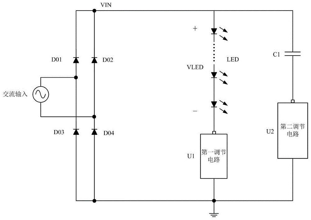
图2为本发明LED控制电路原理图;Fig. 2 is a schematic diagram of the LED control circuit of the present invention;
图3为本发明第一调节电路原理图;Fig. 3 is a schematic diagram of the first regulating circuit of the present invention;
图4为本发明第二调节电路原理图;Fig. 4 is the schematic diagram of the second regulation circuit of the present invention;
图5为本发明LED控制电路波形图;Fig. 5 is a waveform diagram of the LED control circuit of the present invention;
具体实施方式Detailed ways
以下结合附图对本发明的优选实施例进行详细描述,但本发明并不仅仅限于这些实施例。本发明涵盖任何在本发明的精神和范围上做的替代、修改、等效方法以及方案。Preferred embodiments of the present invention will be described in detail below with reference to the accompanying drawings, but the present invention is not limited to these embodiments. The present invention covers any alternatives, modifications, equivalent methods and schemes made within the spirit and scope of the present invention.
为了使公众对本发明有彻底的了解,在以下本发明优选实施例中详细说明了具体的细节,而对本领域技术人员来说没有这些细节的描述也可以完全理解本发明。In order to provide the public with a thorough understanding of the present invention, specific details are set forth in the following preferred embodiments of the present invention, but those skilled in the art can fully understand the present invention without the description of these details.
在下列段落中参照附图以举例方式更具体地描述本发明。需说明的是,附图均采用较为简化的形式且均使用非精准的比例,用以方便、明晰地辅助说明本发明实施例的目的。In the following paragraphs the invention is described more specifically by way of example with reference to the accompanying drawings. It should be noted that all the drawings are in a relatively simplified form and use inaccurate scales to facilitate and clearly assist the purpose of illustrating the embodiments of the present invention.
图2示意了本发明LED驱动电路原理图,交流输入经整流电路后得到输入电压VIN,LED负载导通电压为VLED,所述LED驱动电路包括第一调节电路U1和第二调节电路U2,第一调节电路和LED负载串联组成第一串联电路,第二调节电路和第一电容C1串联组成第二串联电路,第一串联电路与第二串联电路并联。当VIN>VLED时,输入电压VIN对LED负载供电;当VIN<VLED时,第一电容C1对LED负载供电。Fig. 2 schematically shows the schematic diagram of the LED driving circuit of the present invention, the AC input is rectified to obtain the input voltage VIN, the LED load conduction voltage is VLED, and the LED driving circuit includes a first regulating circuit U1 and a second regulating circuit U2, the second A regulating circuit and the LED load are connected in series to form a first series circuit, a second regulating circuit and the first capacitor C1 are connected in series to form a second series circuit, and the first series circuit and the second series circuit are connected in parallel. When VIN>VLED, the input voltage VIN supplies power to the LED load; when VIN<VLED, the first capacitor C1 supplies power to the LED load.
图3示意了本发明第一调节电路原理图,包括第一调整管M1和第一运算放大器U11,第一调整管M1和所述LED负载串联,所述第一运算放大器U11的输出端与第一调整管M1的控制端连接,所述第一运算放大器U11的两个输入端分别接收第一参考电压VREF1和表征LED负载电流的第一采样信号VCS1,使得第一采样信号VCS1趋近于第一参考电压VREF1,即保持流经第一调整管M1的电流相对恒定,第一参考电压VREF1通过调节所述第一调整管M1调节LED负载电流。当然,也可以设置调光控制电路,以控制第一参考电压VREF1,从而控制改变流经第一调整管M1的电流。Fig. 3 shows the schematic diagram of the first regulation circuit of the present invention, including the first regulation transistor M1 and the first operational amplifier U11, the first regulation transistor M1 is connected in series with the LED load, and the output terminal of the first operational amplifier U11 is connected to the first operational amplifier U11. The control terminal of an adjustment transistor M1 is connected, and the two input terminals of the first operational amplifier U11 respectively receive the first reference voltage VREF1 and the first sampling signal VCS1 representing the LED load current, so that the first sampling signal VCS1 approaches the first A reference voltage VREF1, that is, to keep the current flowing through the first adjustment transistor M1 relatively constant, and the first reference voltage VREF1 adjusts the LED load current by adjusting the first adjustment transistor M1. Of course, a dimming control circuit may also be provided to control the first reference voltage VREF1 so as to control and change the current flowing through the first adjustment tube M1.
图4示意了本发明第二调节电路原理图,包括第二调整管M2和第一控制电路,第二调整管M2与第一电容C1串联,第一控制电路与第二调整管M2的控制端连接,用于调节所述第一电容C1两端电压,使其维持稳定。第一控制电路包括第二运算放大器U12和第二电容C2,第二运算放大器U12的两个输入端分别接收表征LED负载电压的第一控制信号VLED’和表征第一电容两端电压的第二控制信号VCAP’,第二运算放大器U12的输出端与第二电容C2相连。通过控制第二调整管M2,使得第二控制信号VCAP’趋近于所述第一控制信号VLED’,使得所述第一电容C1两端电压趋近于所述LED负载电压。第二运算放大器U11的输出端为第一节点,将第一节点电压VCOMP或将其转换后的值作为第二参考信号VREF2。采样流经第二调整管M2的电流作为第二采样信号VCS2,将其连接第三运算放大器U13的第一输入端,将第二参考信号VREF2连接第三运算放大器U13的第二输入端,使得第二采样信号VCS2趋近于所述第二参考信号VREF2。根据第三运算放大器U13同相输入端与反向输入端的比较结果,对第二调整管的控制端进行上拉或下拉,进而控制第一电容的充电电流,来控制第一电容两端电压。Fig. 4 illustrates the schematic diagram of the second adjustment circuit of the present invention, including the second adjustment tube M2 and the first control circuit, the second adjustment tube M2 is connected in series with the first capacitor C1, the first control circuit and the control terminal of the second adjustment tube M2 connected to adjust the voltage across the first capacitor C1 to keep it stable. The first control circuit includes a second operational amplifier U12 and a second capacitor C2. The two input terminals of the second operational amplifier U12 respectively receive the first control signal VLED' representing the LED load voltage and the second control signal VLED' representing the voltage across the first capacitor. For the control signal VCAP', the output end of the second operational amplifier U12 is connected to the second capacitor C2. By controlling the second adjustment transistor M2, the second control signal VCAP' approaches the first control signal VLED', so that the voltage across the first capacitor C1 approaches the LED load voltage. The output terminal of the second operational amplifier U11 is the first node, and the voltage VCOMP of the first node or the converted value thereof is used as the second reference signal VREF2. Sampling the current flowing through the second adjustment transistor M2 as the second sampling signal VCS2, connecting it to the first input terminal of the third operational amplifier U13, and connecting the second reference signal VREF2 to the second input terminal of the third operational amplifier U13, so that The second sampling signal VCS2 approaches the second reference signal VREF2. According to the comparison result between the non-inverting input terminal and the inverting input terminal of the third operational amplifier U13, the control terminal of the second adjustment transistor is pulled up or pulled down, and then the charging current of the first capacitor is controlled to control the voltage across the first capacitor.
进一步地,为了实现高效的功能,第一控制电路还包括参考转换模块,参考转换模块接收所述第一节点电压VCOMP与补偿参数作差得到第二采样信号VREF2,所述补偿参数与输入电压变化趋势相同。为了在高效控制的基础上提高快速启动能力,设置补偿系数按照如下规则:所述补偿参数表征输入电压VIN与LED负载电压VLED之差。Further, in order to realize efficient functions, the first control circuit further includes a reference conversion module, which receives the difference between the first node voltage VCOMP and the compensation parameter to obtain the second sampling signal VREF2, and the compensation parameter and the input voltage change The trend is the same. In order to improve the quick start-up capability on the basis of efficient control, the compensation coefficient is set according to the following rule: the compensation parameter represents the difference between the input voltage VIN and the LED load voltage VLED.
第二调节电路还包括第一二极管D1,第一二极管和第二调整管M2反向并联。The second regulating circuit further includes a first diode D1, and the first diode and the second regulating transistor M2 are connected in antiparallel.
在图4电路的基础上,图5示意了本发明LED驱动电路工作波形图,其中IC1对应图2中第一电容C1充放电电流波形,ILED为LED电流波形,IOUT为整流电路输出电流波形,下凹形的电流使得本发明电路呈现高效的性能。On the basis of the circuit in Fig. 4, Fig. 5 illustrates the working waveform diagram of the LED drive circuit of the present invention, wherein IC1 corresponds to the charge and discharge current waveform of the first capacitor C1 in Fig. 2, ILED is the LED current waveform, and IOUT is the output current waveform of the rectifier circuit, The concave current makes the circuit of the present invention exhibit high efficiency performance.
基于上述LED驱动电路,可以获得相应的LED控制方法,所述LED驱动电路包括第一调节电路和第二调节电路,其特征在于:第一调节电路,与LED负载串联组成第一串联电路,所述第一调节电路接收第一参考电压,所述第一参考电压通过所述第一调节电路调节LED负载电流;第二调节电路,与第一电容串联组成第二串联电路,所述第二串联电路与所述第一串联电路并联;当所述输入电压大于LED负载电压时,所述输入电压对LED负载供电;当所述输入电压小于LED负载电压时,所述第二调节电路对所述LED负载供电。Based on the above LED driving circuit, a corresponding LED control method can be obtained. The LED driving circuit includes a first regulating circuit and a second regulating circuit, and is characterized in that: the first regulating circuit is connected in series with the LED load to form a first series circuit, so The first regulating circuit receives a first reference voltage, and the first reference voltage regulates the LED load current through the first regulating circuit; the second regulating circuit is connected in series with the first capacitor to form a second series circuit, and the second series circuit The circuit is connected in parallel with the first series circuit; when the input voltage is greater than the LED load voltage, the input voltage supplies power to the LED load; when the input voltage is lower than the LED load voltage, the second regulation circuit supplies power to the LED load power supply.
此外,本发明LED驱动电路的技术特征,可以用于本发明LED控制方法。In addition, the technical features of the LED driving circuit of the present invention can be used in the LED control method of the present invention.
以上所述的实施方式,并不构成对该技术方案保护范围的限定。任何在上述实施方式的精神和原则之内所作的修改、等同替换和改进等,均应包含在该技术方案的保护范围之内。The implementation methods described above do not constitute a limitation to the scope of protection of the technical solution. Any modifications, equivalent replacements and improvements made within the spirit and principles of the above implementation methods shall be included in the protection scope of the technical solution.
Claims (9)
Applications Claiming Priority (2)
| Application Number | Priority Date | Filing Date | Title |
|---|---|---|---|
| CN201911399151.8A CN110913532A (en) | 2019-12-30 | 2019-12-30 | LED control circuit and control method |
| CN2019113991518 | 2019-12-30 |
Publications (2)
| Publication Number | Publication Date |
|---|---|
| CN112637996A CN112637996A (en) | 2021-04-09 |
| CN112637996B true CN112637996B (en) | 2023-06-23 |
Family
ID=69813902
Family Applications (5)
| Application Number | Title | Priority Date | Filing Date |
|---|---|---|---|
| CN201911399151.8A Pending CN110913532A (en) | 2019-12-30 | 2019-12-30 | LED control circuit and control method |
| CN202011608902.5A Active CN112616220B (en) | 2019-12-30 | 2019-12-30 | LED control circuit and control method |
| CN202011608893.XA Active CN112533326B (en) | 2019-12-30 | 2020-12-30 | Linear LED Driver Circuit |
| CN202011608926.0A Active CN112637996B (en) | 2019-12-30 | 2020-12-30 | LED driving circuit and control method |
| CN202011608894.4A Active CN113038657B (en) | 2019-12-30 | 2020-12-30 | Linear LED thyristor dimming drive circuit |
Family Applications Before (3)
| Application Number | Title | Priority Date | Filing Date |
|---|---|---|---|
| CN201911399151.8A Pending CN110913532A (en) | 2019-12-30 | 2019-12-30 | LED control circuit and control method |
| CN202011608902.5A Active CN112616220B (en) | 2019-12-30 | 2019-12-30 | LED control circuit and control method |
| CN202011608893.XA Active CN112533326B (en) | 2019-12-30 | 2020-12-30 | Linear LED Driver Circuit |
Family Applications After (1)
| Application Number | Title | Priority Date | Filing Date |
|---|---|---|---|
| CN202011608894.4A Active CN113038657B (en) | 2019-12-30 | 2020-12-30 | Linear LED thyristor dimming drive circuit |
Country Status (1)
| Country | Link |
|---|---|
| CN (5) | CN110913532A (en) |
Families Citing this family (7)
| Publication number | Priority date | Publication date | Assignee | Title |
|---|---|---|---|---|
| CN112072756A (en) * | 2020-09-25 | 2020-12-11 | 杰华特微电子(杭州)有限公司 | Battery pack equalization circuit and equalization method |
| CN114040543B (en) * | 2021-07-20 | 2023-08-29 | 杰华特微电子股份有限公司 | LED linear driving circuit |
| CN114710857B (en) * | 2021-11-26 | 2024-08-23 | 杰华特微电子股份有限公司 | LED drive circuit and LED drive system |
| CN115313839A (en) * | 2022-08-18 | 2022-11-08 | 健达创智科技股份有限公司 | Harmonic wave adjusting circuit, power supply device and lighting equipment |
| CN116685022A (en) * | 2023-06-09 | 2023-09-01 | 矽力杰半导体技术(杭州)有限公司 | LED drive circuit |
| CN116709604A (en) * | 2023-06-09 | 2023-09-05 | 矽力杰半导体技术(杭州)有限公司 | LED driving circuit |
| CN117279147A (en) * | 2023-08-08 | 2023-12-22 | 杰华特微电子股份有限公司 | Linear LED driver circuits and lighting fixtures |
Citations (8)
| Publication number | Priority date | Publication date | Assignee | Title |
|---|---|---|---|---|
| CN106132031A (en) * | 2016-08-20 | 2016-11-16 | 杰华特微电子(杭州)有限公司 | A kind of ripple eliminates circuit, ripple removing method and applies its LED circuit |
| CN107979899A (en) * | 2017-12-27 | 2018-05-01 | 苏州菲达旭微电子有限公司 | A kind of linear general pump feeds constant-current circuit and has its LED light |
| CN107995736A (en) * | 2017-12-15 | 2018-05-04 | 矽力杰半导体技术(杭州)有限公司 | LED drive circuit, power inverter and control method |
| EP3370484A1 (en) * | 2017-03-01 | 2018-09-05 | ATLAS ELEKTRONIK GmbH | Light emitting diode circuit and luminaire |
| CN108633126A (en) * | 2017-03-22 | 2018-10-09 | 华润矽威科技(上海)有限公司 | Linear high power factor constant current is without stroboscopic LED drive circuit and method |
| CN109788606A (en) * | 2018-12-28 | 2019-05-21 | 杰华特微电子(杭州)有限公司 | Ripple eliminates circuit and method and LED circuit |
| CN110392467A (en) * | 2019-07-08 | 2019-10-29 | 杰华特微电子(杭州)有限公司 | LED control circuit and control method |
| EP3576496A1 (en) * | 2018-05-28 | 2019-12-04 | Silergy Semiconductor Technology (Hangzhou) Ltd | Led driver with a silicon controlled dimmer and control method thereof |
Family Cites Families (22)
| Publication number | Priority date | Publication date | Assignee | Title |
|---|---|---|---|---|
| JP3514071B2 (en) * | 1997-05-26 | 2004-03-31 | 株式会社村田製作所 | Smoothing circuit |
| US8299715B2 (en) * | 2010-05-28 | 2012-10-30 | Omnipulse Technology Corporation | Temperature compensated driver for pulsed diode light source |
| CN103023300B (en) * | 2011-09-26 | 2015-03-18 | 英飞特电子(杭州)股份有限公司 | Constant-current control circuit capable of correcting power factors and power factor correcting circuit |
| TW201349927A (en) * | 2012-05-23 | 2013-12-01 | Luxul Technology Inc | Flicker-free LED driver circuit with high power factor |
| CN102740571B (en) * | 2012-07-18 | 2014-10-15 | 矽力杰半导体技术(杭州)有限公司 | Dimmable LED (Light-Emitting Diode) driving circuit and driving method |
| US8680781B1 (en) * | 2012-09-07 | 2014-03-25 | Infineon Technologies Austria Ag | Circuit and method for driving LEDs |
| CN104093257B (en) * | 2014-07-31 | 2017-01-18 | 上海贝岭股份有限公司 | Power regulation circuit for linear LED (light-emitting diode) drive power supply |
| WO2016066400A1 (en) * | 2014-10-30 | 2016-05-06 | Philips Lighting Holding B.V. | An led driver circuit, and led arrangement and a driving method |
| CN104768296B (en) * | 2015-03-31 | 2017-08-25 | 矽力杰半导体技术(杭州)有限公司 | LED dimming driving circuits |
| CN106341923B (en) * | 2016-04-29 | 2018-03-23 | 矽力杰半导体技术(杭州)有限公司 | Control circuit, control method and linear LED drive circuit using same |
| CN105979630B (en) * | 2016-06-08 | 2018-02-09 | 杰华特微电子(杭州)有限公司 | Led drive circuit |
| CN107529241B (en) * | 2016-06-22 | 2019-06-21 | 华润矽威科技(上海)有限公司 | A kind of linear Constant-power LED drive circuit of single hop and method |
| CN106954296A (en) * | 2016-09-23 | 2017-07-14 | 上海占空比电子科技有限公司 | Remove the linear LED drive circuit of stroboscopic |
| CN106961768B (en) * | 2017-04-28 | 2019-02-19 | 南京微客力科技有限公司 | A kind of LED linear constant-current drive circuit of active valley-fill circuit mode |
| CN107623968B (en) * | 2017-10-27 | 2024-03-22 | 上海晶丰明源半导体股份有限公司 | Line voltage compensation circuit, LED driving system and driving method |
| CN110582136B (en) * | 2018-06-08 | 2024-08-02 | 美芯晟科技(北京)股份有限公司 | Dimmable LED driving circuit and control method |
| CN109348587B (en) * | 2018-12-14 | 2021-09-07 | 上海源微电子科技有限公司 | LED constant current drive circuit with high PF does not have stroboscopic |
| CN110324935B (en) * | 2019-06-19 | 2024-05-24 | 杰华特微电子(张家港)有限公司 | Efficient linear LED driving circuit and method |
| CN110461055B (en) * | 2019-06-24 | 2024-03-22 | 杰华特微电子股份有限公司 | Lighting driving circuit and method and lighting system |
| CN110519881B (en) * | 2019-07-16 | 2022-05-13 | 深圳市稳先微电子有限公司 | LED driving circuit and control method thereof |
| CN110572897B (en) * | 2019-08-20 | 2024-03-19 | 深圳市晟碟半导体有限公司 | High-power-factor stroboflash-free LED dimming circuit, device and dimming method |
| CN110582143B (en) * | 2019-10-09 | 2024-06-28 | 杰华特微电子股份有限公司 | LED dimming circuit, dimming method and LED control circuit |
-
2019
- 2019-12-30 CN CN201911399151.8A patent/CN110913532A/en active Pending
- 2019-12-30 CN CN202011608902.5A patent/CN112616220B/en active Active
-
2020
- 2020-12-30 CN CN202011608893.XA patent/CN112533326B/en active Active
- 2020-12-30 CN CN202011608926.0A patent/CN112637996B/en active Active
- 2020-12-30 CN CN202011608894.4A patent/CN113038657B/en active Active
Patent Citations (8)
| Publication number | Priority date | Publication date | Assignee | Title |
|---|---|---|---|---|
| CN106132031A (en) * | 2016-08-20 | 2016-11-16 | 杰华特微电子(杭州)有限公司 | A kind of ripple eliminates circuit, ripple removing method and applies its LED circuit |
| EP3370484A1 (en) * | 2017-03-01 | 2018-09-05 | ATLAS ELEKTRONIK GmbH | Light emitting diode circuit and luminaire |
| CN108633126A (en) * | 2017-03-22 | 2018-10-09 | 华润矽威科技(上海)有限公司 | Linear high power factor constant current is without stroboscopic LED drive circuit and method |
| CN107995736A (en) * | 2017-12-15 | 2018-05-04 | 矽力杰半导体技术(杭州)有限公司 | LED drive circuit, power inverter and control method |
| CN107979899A (en) * | 2017-12-27 | 2018-05-01 | 苏州菲达旭微电子有限公司 | A kind of linear general pump feeds constant-current circuit and has its LED light |
| EP3576496A1 (en) * | 2018-05-28 | 2019-12-04 | Silergy Semiconductor Technology (Hangzhou) Ltd | Led driver with a silicon controlled dimmer and control method thereof |
| CN109788606A (en) * | 2018-12-28 | 2019-05-21 | 杰华特微电子(杭州)有限公司 | Ripple eliminates circuit and method and LED circuit |
| CN110392467A (en) * | 2019-07-08 | 2019-10-29 | 杰华特微电子(杭州)有限公司 | LED control circuit and control method |
Also Published As
| Publication number | Publication date |
|---|---|
| CN112533326B (en) | 2023-06-23 |
| CN112637996A (en) | 2021-04-09 |
| CN113038657B (en) | 2023-06-23 |
| CN112533326A (en) | 2021-03-19 |
| CN112616220A (en) | 2021-04-06 |
| CN110913532A (en) | 2020-03-24 |
| CN113038657A (en) | 2021-06-25 |
| CN112616220B (en) | 2023-03-14 |
Similar Documents
| Publication | Publication Date | Title |
|---|---|---|
| CN113038657B (en) | Linear LED thyristor dimming drive circuit | |
| CN102695341B (en) | LED drive power supply applicable to electronic transformer | |
| CN103490630B (en) | For control circuit and the control method of staggered-parallel-type Switching Power Supply | |
| TW201531162A (en) | Dimming method and circuit and controllable silicon dimming circuit with circuit | |
| CN104407659B (en) | The output current sample circuit of supply convertor and output voltage compensating circuit | |
| CN106160434B (en) | Ripple wave suppression method and circuit and load driving circuit applying same | |
| CN102143638A (en) | A thyristor dimming circuit, dimming method and an LED driver using the same | |
| CN102752940A (en) | High-efficiency LED (light-emitting diode) drive circuit and drive method thereof | |
| CN107592705B (en) | Dimmable LED drive circuit and dimming method | |
| CN103490632B (en) | Step-up step-down type output voltage balancing circuit | |
| CN104812121A (en) | LED driving circuit | |
| CN103117734A (en) | Peak detection circuit, input feed-forward compensating circuit and power factor correction circuit | |
| CN104219855A (en) | Strobe-free LED constant-flow drive control circuit based on APFC | |
| CN205546103U (en) | A Flyback drive circuit | |
| CN103179755B (en) | A kind of LED linear constant current driving governor with High Power Factor | |
| CN110545603B (en) | A power compensation circuit for LED lamp | |
| CN205546102U (en) | A kind of LED driving circuit | |
| CN109618463B (en) | LED driving power supply dimming method without electrolytic capacitor | |
| CN105792437B (en) | A kind of LED drive circuit | |
| CN105792436B (en) | The controller and Switching Power Supply of Switching Power Supply | |
| CN214337787U (en) | Control circuit of switching power supply circuit and switching power supply | |
| CN209389940U (en) | Constant Current Control Circuit for LLC Resonant Converter | |
| CN205546101U (en) | A kind of LED driving circuit | |
| CN208723784U (en) | A kind of pfc converter of constant current output | |
| CN106793294B (en) | driving circuit |
Legal Events
| Date | Code | Title | Description |
|---|---|---|---|
| PB01 | Publication | ||
| PB01 | Publication | ||
| SE01 | Entry into force of request for substantive examination | ||
| SE01 | Entry into force of request for substantive examination | ||
| CB02 | Change of applicant information |
Address after: Room 901-23, 9 / F, west 4 building, Xigang development center, 298 Zhenhua Road, Sandun Town, Xihu District, Hangzhou City, Zhejiang Province, 310030 Applicant after: Jiehuate Microelectronics Co.,Ltd. Address before: Room 901-23, 9 / F, west 4 building, Xigang development center, 298 Zhenhua Road, Sandun Town, Xihu District, Hangzhou City, Zhejiang Province, 310030 Applicant before: JOULWATT TECHNOLOGY Inc.,Ltd. |
|
| CB02 | Change of applicant information | ||
| GR01 | Patent grant | ||
| GR01 | Patent grant | ||
| CP03 | Change of name, title or address |
Address after: 310030 Zhejiang Province, Hangzhou City, Xihu District, Sandun Town, Shengtangba Street No. 19, Shengtang Xin Cheng Patentee after: Jiehuate Microelectronics Co.,Ltd. Country or region after: China Address before: Room 901-23, 9 / F, west 4 building, Xigang development center, 298 Zhenhua Road, Sandun Town, Xihu District, Hangzhou City, Zhejiang Province, 310030 Patentee before: Jiehuate Microelectronics Co.,Ltd. Country or region before: China |
|
| CP03 | Change of name, title or address |