CN112626984A - Automatic paving device for curbstone - Google Patents
Automatic paving device for curbstone Download PDFInfo
- Publication number
- CN112626984A CN112626984A CN202011618809.2A CN202011618809A CN112626984A CN 112626984 A CN112626984 A CN 112626984A CN 202011618809 A CN202011618809 A CN 202011618809A CN 112626984 A CN112626984 A CN 112626984A
- Authority
- CN
- China
- Prior art keywords
- hinged
- bottom plate
- rotating
- push rod
- hydraulic push
- Prior art date
- Legal status (The legal status is an assumption and is not a legal conclusion. Google has not performed a legal analysis and makes no representation as to the accuracy of the status listed.)
- Granted
Links
- 230000005540 biological transmission Effects 0.000 claims description 21
- 239000000725 suspension Substances 0.000 claims description 4
- 238000009434 installation Methods 0.000 abstract description 8
- 239000004570 mortar (masonry) Substances 0.000 description 5
- 239000004575 stone Substances 0.000 description 4
- 208000032370 Secondary transmission Diseases 0.000 description 1
- 230000004075 alteration Effects 0.000 description 1
- 238000010276 construction Methods 0.000 description 1
- 238000002955 isolation Methods 0.000 description 1
- 230000004048 modification Effects 0.000 description 1
- 238000012986 modification Methods 0.000 description 1
- 238000006467 substitution reaction Methods 0.000 description 1
- 230000007306 turnover Effects 0.000 description 1
Images


Classifications
-
- E—FIXED CONSTRUCTIONS
- E01—CONSTRUCTION OF ROADS, RAILWAYS, OR BRIDGES
- E01C—CONSTRUCTION OF, OR SURFACES FOR, ROADS, SPORTS GROUNDS, OR THE LIKE; MACHINES OR AUXILIARY TOOLS FOR CONSTRUCTION OR REPAIR
- E01C19/00—Machines, tools or auxiliary devices for preparing or distributing paving materials, for working the placed materials, or for forming, consolidating, or finishing the paving
- E01C19/52—Apparatus for laying individual preformed surfacing elements, e.g. kerbstones
- E01C19/522—Apparatus for laying the elements by rolling or unfolding, e.g. for temporary pavings
Landscapes
- Engineering & Computer Science (AREA)
- Architecture (AREA)
- Civil Engineering (AREA)
- Structural Engineering (AREA)
- Road Paving Machines (AREA)
Abstract
The invention discloses an automatic paving device for curbstones, which comprises a bottom plate, universal wheels, fixed wheels, pull rings, a leveling device and a hoisting device, wherein the universal wheels are respectively arranged on the left side and the right side of the front part of the lower end of the bottom plate, the fixed wheels are respectively arranged on the left side and the right side of the rear part of the lower end of the bottom plate, the pull rings are horizontally fixed in the middle of the front end of the bottom plate, the leveling device is arranged on the front part of the upper end of the bottom plate, and the hoisting device is. The hydraulic leveling device is simple in structure, the height of the leveling device is controlled through the leveling device so as to adapt to grooves with depth and curbstones with different heights, the inclination angle of the leveling device can be controlled through the inclined hydraulic push rod so as to adapt to installation of the curbstones on inclined pavement, errors caused by manual leveling are reduced, the installation of the curbstones is more accurate, the rapid installation of the curbstones is realized through the hoisting device, the installation efficiency is accelerated, and the use of manpower is reduced.
Description
Technical Field
The invention relates to the field of road construction, in particular to an automatic paving device for road edge stones.
Background
The curb stone is a boundary stone generally used for the edge of a road surface, also called a road curb stone or a kerbstone, is a boundary line for distinguishing a traffic lane, a sidewalk, a green land, an isolation strip and other parts of the road on the road surface, and plays a role in guaranteeing the traffic safety of pedestrians and vehicles and ensuring the edge of the road surface to be neat. When current curbstone was laid, need pour into mortar to the ditch inslot dug earlier, then make level the back with the mortar and place curbstone, and need the up end of mortar and road surface to keep certain height when the mortar is made level, and the manual work is looked for at ordinary times, the deviation of precision appears easily for a long time easily, and the manual work is made level and is taken trouble hard.
Disclosure of Invention
The invention aims to provide an automatic paving device for a curbstone, which aims to solve the technical problem.
In order to achieve the purpose, the invention adopts the following technical scheme:
the utility model provides an automatic laying device of curbstone, includes bottom plate, universal wheel, tight pulley, pull ring, leveling device, hoist device, the universal wheel is respectively installed to the anterior left and right sides of bottom plate lower extreme, and respectively installs the tight pulley in the bottom plate lower extreme rear portion left and right sides, bottom plate front end middle part level is fixed with the pull ring, bottom plate upper end forward-mounted has leveling device, and installs hoist device in bottom plate upper end rear portion.
On the basis of the technical scheme, the leveling device comprises a rotating fluted disc, pedals, an operating platform, a rotating motor, gears, control rods, a leveling device, a lifting hydraulic push rod, a connecting column, an inclined hydraulic push rod, a main transmission rod, an auxiliary transmission rod and a hinge frame, wherein the rotating fluted disc is horizontally hinged on the front side of the middle part of the upper end of the bottom plate, the pedals are horizontally fixed on the upper end of the rotating fluted disc, the operating platform is vertically installed at the upper end of the front part of the pedals, the rotating motor is vertically installed at the rear part of the right side of the upper end of the pedals, the gears are horizontally installed at the lower part of the pedals and are meshed with the rotating fluted disc, a rotating shaft of the rotating motor vertically penetrates through the pedals and is fixedly connected with the middle part of the upper end of the gears, the left side and the right side of the upper part of the front end of the, and the operation panel front end respectively articulates there is the hydraulic push rod that lifts, two the hydraulic push rod front end that lifts is articulated with two control lever rear end middle parts respectively, two the level is fixed with the spliced pole between the control lever middle part, operation panel front end middle part level articulates there is slope hydraulic push rod, and the hydraulic push rod front end that inclines articulates with main drive line upper end middle part, main drive line lower extreme middle part level articulates there is the auxiliary transmission pole, and the auxiliary transmission pole front end with push away the flat ware rear end upper side middle part and articulate, the spliced pole front end is fixed with articulated frame, and both ends are articulated about articulated frame and the main drive line middle part.
On the basis of the technical scheme, the leveler comprises a left limiting plate, a right limiting plate, an angle adjusting hinged plate, a limiting sliding column, a leveling hydraulic push rod, a sliding plate and a shunting push block, wherein the angle adjusting hinged plate is fixed on the middle side of the position between the left limiting plate and the right limiting plate, the middle part of the angle adjusting hinged plate is hinged to the front end of a secondary transmission rod, the limiting sliding column is fixed on the front side and the rear side of the lower part of the position between the left limiting plate and the right limiting plate respectively, the leveling hydraulic push rod is horizontally installed at the middle part of the left limiting plate, the left limiting plate is penetrated by the right side of the leveling hydraulic push rod, the sliding plate is vertically fixed at the right end of the leveling hydraulic push rod, the lower part of the sliding plate is connected with the two limiting sliding.
On the basis of the technical scheme, the hoisting device comprises a rotary chassis, a lower rotary fluted disc, a lower rotary motor, a lower gear, a vertical beam, a cross beam, a hydraulic height adjusting rod, a hanging clamp and a lifting rope, wherein the rotary chassis is horizontally arranged at the rear part of the upper end of the bottom plate, the middle part of the lower end of the rotary chassis penetrates through the bottom plate, a lower rotary fluted disc is fixed at the lower end of the rotary chassis, a lower rotating motor is vertically arranged at the rear part of the right side of the upper end of the bottom plate, a rotating shaft of the lower rotating motor vertically penetrates through the bottom plate, a lower gear is horizontally fixed at the lower end of the rotating shaft of the lower rotating motor, the lower gear is meshed with a lower rotating fluted disc, a vertical beam is vertically arranged at the front part of the upper end of the rotating chassis, the upper end of the vertical beam is hinged with a cross beam, the rear part of the upper end of the rotating chassis is vertically fixed with a hydraulic height adjusting rod, and the upper end of the hydraulic height adjusting rod is hinged to the front side of the lower end of the cross beam, and the left side and the right side of the upper end of the suspension clamp are connected with the rear end of the cross beam through suspension ropes.
Compared with the prior art, the invention has the following advantages: the hydraulic leveling device is simple in structure, the height of the leveling device is controlled through the leveling device so as to adapt to grooves with depth and curbstones with different heights, the inclination angle of the leveling device can be controlled through the inclined hydraulic push rod so as to adapt to installation of the curbstones on inclined pavement, errors caused by manual leveling are reduced, the installation of the curbstones is more accurate, the rapid installation of the curbstones is realized through the hoisting device, the installation efficiency is accelerated, and the use of manpower is reduced.
Drawings
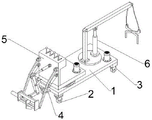
Fig. 1 is a schematic view of the external structure of the present invention.
FIG. 2 is a cross-sectional, partially enlarged schematic view of a pedal of the present invention.
FIG. 3 is a partially enlarged view of the flattener of the present invention.
Fig. 4 is a rear cross-sectional partially enlarged view of the bottom plate of the present invention.
In the figure: 1. the device comprises a base plate, 2, universal wheels, 3, fixed wheels, 4, pull rings, 5, a leveling device, 6, a hoisting device, 7, a transmission fluted disc, 8, a pedal, 9, an operation table, 10, a rotating motor, 11, gears, 12, a control rod, 13, a leveler, 14, a lifting hydraulic push rod, 15, a connecting column, 16, an inclined hydraulic push rod, 17, a main transmission rod, 18, an auxiliary transmission rod, 19, a hinged frame, 20, a left limiting plate, 21, a right limiting plate, 22, an angle hinged plate, 23, a limiting sliding column, 24, a leveling hydraulic push rod, 25, a sliding plate, 26, a shunting push block, 27, a chassis, 28, a lower transmission fluted disc, 29, a lower rotating motor, 30, a lower fluted disc, 31, a vertical beam, 32, a cross beam, 33, a hydraulic height adjusting rod, 34, a hanging clamp, 35 and a hanging rope.
Detailed Description
The invention is explained in further detail below with reference to the figures and the specific embodiments.
As shown in fig. 1-4, an automatic paving device of curbstone, including bottom plate 1, universal wheel 2, tight pulley 3, pull ring 4, leveling device 5, hoist device 6, universal wheel 2 is respectively installed to the anterior left and right sides of bottom plate 1 lower extreme, and the tight pulley 3 is respectively installed to the 1 lower extreme rear portion left and right sides of bottom plate, 1 front end middle part horizontal fixation of bottom plate has pull ring 4, 1 upper end forward-mounted of bottom plate has leveling device 5, and 1 upper end rear portion of bottom plate installs hoist device 6.
The leveling device 5 comprises a rotary fluted disc 7, pedals 8, an operating platform 9, a rotary motor 10, gears 11, control rods 12, a leveling device 13, a lifting hydraulic push rod 14, a connecting column 15, an inclined hydraulic push rod 16, a main transmission rod 17, an auxiliary transmission rod 18 and a hinge frame 19, wherein the rotary fluted disc 7 is horizontally hinged to the front side of the middle part of the upper end of the bottom plate 1, the pedals 8 are horizontally fixed to the upper end of the rotary fluted disc 7, the operating platform 9 is vertically installed at the upper end of the front part of each pedal 8, the rotary motor 10 is vertically installed at the rear part of the right side of the upper end of each pedal 8, the gears 11 are horizontally installed on the lower part of each pedal 8, the gears 11 are meshed with the rotary fluted disc 7, a rotating shaft of the rotary motor 10 vertically penetrates through the pedals 8 and is fixedly connected with the middle part of the upper end of the gears 11, the left side and the right side of the upper part of the upper end of, two 12 downside of control lever, and 9 front ends of operation panel respectively articulate and have lift hydraulic push rod 14, two lift hydraulic push rod 14 front end is articulated with two 12 rear end middle parts of control lever respectively, two the level is fixed with spliced pole 15 between 12 middle parts of control lever, 9 front end middle part levels of operation panel articulate has slope hydraulic push rod 16, and 16 front ends of slope hydraulic push rod are articulated with 17 upper end middle parts of final drive pole, 17 lower extreme middle parts levels of final drive pole articulate has auxiliary drive pole 18, and 18 front ends of auxiliary drive pole and 13 rear ends of pushing flat ware upper sides middle parts articulate, 15 front ends of spliced pole are fixed with articulated frame 19, and articulated frame 19 and final drive pole 17 middle parts are controlled both ends and are articulated.
The device 13 comprises a left limiting plate 20, a right limiting plate 21, an angle adjusting hinged plate 22, a limiting sliding column 23, a leveling hydraulic push rod 24, a sliding plate 25 and a shunting push block 26, wherein the angle adjusting hinged plate 22 is fixed on the upper side of the middle between the left limiting plate 20 and the right limiting plate 21, the rear middle of the angle adjusting hinged plate 22 is hinged to the front end of the auxiliary transmission rod 18, the limiting sliding column 23 is fixed on the front side and the rear side of the lower portion between the left limiting plate 20 and the right limiting plate 21 respectively, the leveling hydraulic push rod 24 is horizontally installed in the middle of the left end of the left limiting plate 20, the left limiting plate 20 is penetrated through the right side of the leveling hydraulic push rod 24, the sliding plate 25 is vertically fixed on the right end of the leveling hydraulic push rod 24, the lower portion of the sliding plate 25 is connected with the two limiting sliding columns.
The hoisting device 6 comprises a rotary chassis 27, a lower rotary fluted disc 28, a lower rotary motor 29, a lower gear 30, a vertical beam 31, a cross beam 32, a hydraulic height adjusting rod 33, a hanging clamp 34 and a hanging rope 35, wherein the rear part of the upper end of the bottom plate 1 is horizontally provided with the rotary chassis 27, the middle part of the lower end of the rotary chassis 27 penetrates through the bottom plate 1, the lower end of the rotary chassis 1 is fixed with the lower rotary fluted disc 28, the lower rotary motor 29 is vertically arranged at the rear part of the right side of the upper end of the bottom plate 1, the rotating shaft of the lower rotary motor 29 vertically penetrates through the bottom plate 1, the lower end of the rotating shaft of the lower rotary motor 29 is horizontally provided with the lower gear 30, the lower gear 30 is meshed with the lower rotary fluted disc 28, the vertical beam 31 is vertically arranged at the front part of the upper end of the rotary chassis 27, the upper end of the vertical beam 31 is hinged with the cross beam 32, the left and right sides of the upper end of the hanging clip 34 are connected with the rear end of the cross beam 32 through a hanging rope 35.
The working principle of the invention is as follows: the bottom plate 1 is parallel to the roadside, the motor 10 is rotated to drive the gear 11 to rotate, the transmission gear disc 7 drives the pedal 8 to rotate by being meshed with the gear 11, the two lifting hydraulic push rods 14 respectively push the two control rods 12 to turn over so as to control the height of the flattening device 13, the flattening device 13 is placed in the dug groove, the inclination angle of the flattening device 13 is adjusted by inclining the hydraulic push rods 16 to enable the flattening device 13 to be parallel to the ground, the sliding plate 25 is pushed by the flattening hydraulic push rod 24 to slide along the two limit sliding columns 23, the sliding plate 25 drives the shunt push block 26 to flatten mortar in the groove, the lower rotating motor 29 drives the lower gear disc 30 to rotate, the lower transmission gear disc 28 is meshed with the lower gear disc 30 to drive the chassis 27 to rotate, the lifting clamp 34 clamps the curb, the hydraulic height adjusting rod 33 upwards pushes the cross beam 32, the cross beam 32 pulls the lifting clamp 34 through the lifting rope 35 to lift the curb, the chassis 27 rotates to one side of the groove, the hydraulic height adjustment rods 33 lower the height of the cross beam 32 to lower the curb down.
The foregoing is a preferred embodiment of the present invention, and it will be apparent to those skilled in the art that variations, modifications, substitutions and alterations can be made in the embodiment without departing from the principles and spirit of the invention.
Claims (3)
1. The utility model provides an automatic laying device of curbstone, includes bottom plate (1), universal wheel (2), tight pulley (3), pull ring (4), leveling device (5), hoist device (6), its characterized in that: universal wheels (2) are respectively installed on the left side and the right side of the front portion of the lower end of the bottom plate (1), fixed wheels (3) are respectively installed on the left side and the right side of the rear portion of the lower end of the bottom plate (1), a pull ring (4) is horizontally fixed in the middle of the front end of the bottom plate (1), a leveling device (5) is installed on the front portion of the upper end of the bottom plate (1), and a hoisting device (6) is installed on the rear portion of the upper end; the leveling device (5) comprises a rotating fluted disc (7), a pedal (8), an operating platform (9), a rotating motor (10), a gear (11), a control rod (12), a leveling device (13), a lifting hydraulic push rod (14), a connecting column (15), an inclined hydraulic push rod (16), a main transmission rod (17), an auxiliary transmission rod (18) and a hinge frame (19), wherein the rotating fluted disc (7) is horizontally hinged to the front side of the middle part of the upper end of the bottom plate (1), the pedal (8) is horizontally fixed to the upper end of the rotating fluted disc (7), the operating platform (9) is vertically installed at the upper end of the front part of the pedal (8), the rotating motor (10) is vertically installed at the rear part of the right side of the upper end of the pedal (8), the gear (11) is horizontally installed at the lower part of the pedal (8), the gear (11) is meshed with the rotating fluted disc (7), and a rotating shaft of the rotating motor (10) vertically penetrates through the, the left side and the right side of the upper part of the front end of the operating platform (9) are respectively hinged with a control rod (12), the lower part of the front side between the two control rods (12) is hinged with a leveling device (13), the lower sides of the control rods (12) are two, the front end of the operating platform (9) is respectively hinged with a lifting hydraulic push rod (14), the front end of the lifting hydraulic push rod (14) is respectively hinged with the middle parts of the rear ends of the two control rods (12), a connecting column (15) is horizontally fixed between the middle parts of the control rods (12), the middle part of the front end of the operating platform (9) is horizontally hinged with an inclined hydraulic push rod (16), the front end of the inclined hydraulic push rod (16) is hinged with the middle part of the upper end of a main transmission rod (17), the middle part of the lower end of the main transmission rod (17) is horizontally hinged with an auxiliary transmission rod (18), the front end of the auxiliary transmission rod (18) is hinged with the, and the hinged frame (19) is hinged with the left end and the right end of the middle part of the main transmission rod (17).
2. An automated paving apparatus for curbstones according to claim 1, wherein: the leveling device (13) comprises a left limiting plate (20), a right limiting plate (21), an angle adjusting hinged plate (22), a limiting sliding column (23), a leveling hydraulic push rod (24), a sliding plate (25) and a shunting push block (26), wherein the angle adjusting hinged plate (22) is horizontally fixed on the upper side of the middle part between the left limiting plate (20) and the right limiting plate (21), the middle part of the rear end of the angle adjusting hinged plate (22) is hinged with the front end of an auxiliary transmission rod (18), the limiting sliding columns (23) are horizontally fixed on the front side and the rear side of the lower part between the left limiting plate (20) and the right limiting plate (21), the leveling hydraulic push rod (24) is horizontally installed in the middle part of the left end of the left limiting plate (20), the right side of the leveling hydraulic push rod (24) penetrates through the left limiting plate (20), the right end of the leveling hydraulic push rod (24) is vertically fixed with the sliding plate (25), and the lower part of, and a shunting push block (26) is fixed at the lower end of the sliding plate (25).
3. An automated paving apparatus for curbstones according to claim 1, wherein: the hoisting device (6) comprises a rotating chassis (27), a lower rotating fluted disc (28), a lower rotating motor (29), a lower gear (30), a vertical beam (31), a cross beam (32), a hydraulic height adjusting rod (33), a hanging clamp (34) and a lifting rope (35), wherein the rear part of the upper end of the bottom plate (1) is horizontally provided with the rotating chassis (27), the middle part of the lower end of the rotating chassis (27) penetrates through the bottom plate (1), the lower end of the rotating chassis (1) is fixed with the lower rotating fluted disc (28), the lower rotating motor (29) is vertically arranged at the rear part of the right side of the upper end of the bottom plate (1), the rotating shaft of the lower rotating motor (29) vertically penetrates through the bottom plate (1), the lower gear (30) is horizontally fixed at the lower end of the rotating motor (29), the lower gear (30) is meshed with the lower rotating fluted disc (28), and the vertical, and the upper end of the vertical beam (31) is hinged with a cross beam (32), the rear part of the upper end of the rotating chassis (27) is vertically fixed with a hydraulic height adjusting rod (33), the upper end of the hydraulic height adjusting rod (33) is hinged to the front side of the lower end of the cross beam (32), and the left side and the right side of the upper end of the suspension clamp (34) are connected with the rear end of the cross beam (32) through suspension ropes (35).
Priority Applications (1)
| Application Number | Priority Date | Filing Date | Title |
|---|---|---|---|
| CN202011618809.2A CN112626984B (en) | 2020-12-31 | 2020-12-31 | Automatic paving device for curbstone |
Applications Claiming Priority (1)
| Application Number | Priority Date | Filing Date | Title |
|---|---|---|---|
| CN202011618809.2A CN112626984B (en) | 2020-12-31 | 2020-12-31 | Automatic paving device for curbstone |
Publications (2)
| Publication Number | Publication Date |
|---|---|
| CN112626984A true CN112626984A (en) | 2021-04-09 |
| CN112626984B CN112626984B (en) | 2022-11-08 |
Family
ID=75287460
Family Applications (1)
| Application Number | Title | Priority Date | Filing Date |
|---|---|---|---|
| CN202011618809.2A Active CN112626984B (en) | 2020-12-31 | 2020-12-31 | Automatic paving device for curbstone |
Country Status (1)
| Country | Link |
|---|---|
| CN (1) | CN112626984B (en) |
Cited By (1)
| Publication number | Priority date | Publication date | Assignee | Title |
|---|---|---|---|---|
| CN114673058A (en) * | 2022-04-27 | 2022-06-28 | 中国十七冶集团有限公司 | Curb mounting device and method |
Citations (5)
| Publication number | Priority date | Publication date | Assignee | Title |
|---|---|---|---|---|
| GB1136444A (en) * | 1965-11-09 | 1968-12-11 | Arthur Lennart Bergkvist | Method of laying a kerbstone |
| CN201660853U (en) * | 2010-02-09 | 2010-12-01 | 王建华 | Road-edge stone convenient in construction |
| CN205443877U (en) * | 2016-02-24 | 2016-08-10 | 南通威而多专用汽车制造有限公司 | Flush trimmer system of wheeled slipform curbstone paver |
| CN210113320U (en) * | 2019-05-30 | 2020-02-25 | 李建华 | Road shoulder leveling machine |
| CN210855050U (en) * | 2019-08-27 | 2020-06-26 | 中国二十冶集团有限公司 | Curbstone installation trolley |
-
2020
- 2020-12-31 CN CN202011618809.2A patent/CN112626984B/en active Active
Patent Citations (5)
| Publication number | Priority date | Publication date | Assignee | Title |
|---|---|---|---|---|
| GB1136444A (en) * | 1965-11-09 | 1968-12-11 | Arthur Lennart Bergkvist | Method of laying a kerbstone |
| CN201660853U (en) * | 2010-02-09 | 2010-12-01 | 王建华 | Road-edge stone convenient in construction |
| CN205443877U (en) * | 2016-02-24 | 2016-08-10 | 南通威而多专用汽车制造有限公司 | Flush trimmer system of wheeled slipform curbstone paver |
| CN210113320U (en) * | 2019-05-30 | 2020-02-25 | 李建华 | Road shoulder leveling machine |
| CN210855050U (en) * | 2019-08-27 | 2020-06-26 | 中国二十冶集团有限公司 | Curbstone installation trolley |
Cited By (2)
| Publication number | Priority date | Publication date | Assignee | Title |
|---|---|---|---|---|
| CN114673058A (en) * | 2022-04-27 | 2022-06-28 | 中国十七冶集团有限公司 | Curb mounting device and method |
| CN114673058B (en) * | 2022-04-27 | 2023-09-15 | 中国十七冶集团有限公司 | Curb installation device and installation method |
Also Published As
| Publication number | Publication date |
|---|---|
| CN112626984B (en) | 2022-11-08 |
Similar Documents
| Publication | Publication Date | Title |
|---|---|---|
| CN111188247B (en) | Road curb erection and laying equipment | |
| CN116575430A (en) | Earthwork rolling and compacting equipment for slope construction and its implementation method | |
| CN110847818A (en) | Walking drilling machine | |
| CN112626984B (en) | Automatic paving device for curbstone | |
| CN109454746A (en) | Concrete pouring device for building construction and construction method thereof | |
| CN218620033U (en) | Curb construction equipment | |
| CN210194392U (en) | A road leveling device for municipal engineering construction | |
| CN112726363B (en) | Pavement cutting equipment and method for highway construction | |
| CN114908825A (en) | Intelligent soil surface leveling machine and using method thereof | |
| CN213802829U (en) | Pavement manhole cover opening device | |
| CN221167323U (en) | Vibrator is laid to sand material | |
| CN210797190U (en) | Asphalt laying device for road construction | |
| CN218711972U (en) | Town road construction device of levelling that shakes | |
| CN223445958U (en) | Multifunctional curb construction device | |
| CN116002539A (en) | Curb stone hoisting and installation of electric flatbed truck | |
| CN218373071U (en) | Road design roadbed reinforced structure | |
| CN117536069B (en) | Road subgrade subsidence treatment device | |
| CN223510241U (en) | Curbstone Auxiliary Installation Trolley | |
| CN217149813U (en) | Laying device for laying environment-friendly green sidewalk | |
| CN223215892U (en) | Water conservancy pipeline installation auxiliary stay device | |
| CN112459037A (en) | Highway construction's of reducible raise dust ground tamping unit | |
| CN112408290B (en) | A paved manhole cover opening device | |
| CN219547700U (en) | Simple continuous joint cutter | |
| CN223386498U (en) | Asphalt concrete paving auxiliary equipment | |
| CN220035130U (en) | Curb auxiliary dragging device |
Legal Events
| Date | Code | Title | Description |
|---|---|---|---|
| PB01 | Publication | ||
| PB01 | Publication | ||
| SE01 | Entry into force of request for substantive examination | ||
| SE01 | Entry into force of request for substantive examination | ||
| TA01 | Transfer of patent application right |
Effective date of registration: 20221019 Address after: 471002 No. 8 Yangwen Xiangyang Road, Hanghe District, Luoyang City, Henan Province Applicant after: CCCC SECOND HIGHWAY FOURTH ENGINEERING Co.,Ltd. Address before: Room 12-a057, zero one square, Xi'an Software Park, 72 Keji 2nd Road, Zhangba Street office, high tech Zone, Xi'an, Shaanxi 710000 Applicant before: Xi'an Baoxin automation equipment Co.,Ltd. |
|
| TA01 | Transfer of patent application right | ||
| GR01 | Patent grant | ||
| GR01 | Patent grant |