CN112621910A - A but, equipment that is used for plank drilling and polishes and recycle - Google Patents
A but, equipment that is used for plank drilling and polishes and recycle Download PDFInfo
- Publication number
- CN112621910A CN112621910A CN202110057809.8A CN202110057809A CN112621910A CN 112621910 A CN112621910 A CN 112621910A CN 202110057809 A CN202110057809 A CN 202110057809A CN 112621910 A CN112621910 A CN 112621910A
- Authority
- CN
- China
- Prior art keywords
- fixedly connected
- cavity
- face
- shaft
- side end
- Prior art date
- Legal status (The legal status is an assumption and is not a legal conclusion. Google has not performed a legal analysis and makes no representation as to the accuracy of the status listed.)
- Withdrawn
Links
- 238000005553 drilling Methods 0.000 title claims abstract description 43
- 239000002023 wood Substances 0.000 claims abstract description 57
- 238000005498 polishing Methods 0.000 claims abstract description 44
- 238000004064 recycling Methods 0.000 claims abstract description 22
- 230000005540 biological transmission Effects 0.000 claims description 34
- 238000001125 extrusion Methods 0.000 claims description 33
- 238000011084 recovery Methods 0.000 claims description 28
- 239000000428 dust Substances 0.000 claims description 19
- 238000000227 grinding Methods 0.000 claims description 19
- 238000005192 partition Methods 0.000 claims description 15
- 238000010521 absorption reaction Methods 0.000 claims description 8
- 238000003754 machining Methods 0.000 claims description 4
- 238000007790 scraping Methods 0.000 claims 1
- 230000007704 transition Effects 0.000 abstract description 3
- 230000001960 triggered effect Effects 0.000 abstract description 3
- 230000009286 beneficial effect Effects 0.000 description 2
- 230000006835 compression Effects 0.000 description 2
- 238000007906 compression Methods 0.000 description 2
- 230000001360 synchronised effect Effects 0.000 description 1
Images



Classifications
-
- B—PERFORMING OPERATIONS; TRANSPORTING
- B27—WORKING OR PRESERVING WOOD OR SIMILAR MATERIAL; NAILING OR STAPLING MACHINES IN GENERAL
- B27C—PLANING, DRILLING, MILLING, TURNING OR UNIVERSAL MACHINES FOR WOOD OR SIMILAR MATERIAL
- B27C3/00—Drilling machines or drilling devices; Equipment therefor
- B27C3/02—Stationary drilling machines with a single working spindle
-
- B—PERFORMING OPERATIONS; TRANSPORTING
- B24—GRINDING; POLISHING
- B24B—MACHINES, DEVICES, OR PROCESSES FOR GRINDING OR POLISHING; DRESSING OR CONDITIONING OF ABRADING SURFACES; FEEDING OF GRINDING, POLISHING, OR LAPPING AGENTS
- B24B41/00—Component parts such as frames, beds, carriages, headstocks
- B24B41/06—Work supports, e.g. adjustable steadies
- B24B41/068—Table-like supports for panels, sheets or the like
-
- B—PERFORMING OPERATIONS; TRANSPORTING
- B24—GRINDING; POLISHING
- B24B—MACHINES, DEVICES, OR PROCESSES FOR GRINDING OR POLISHING; DRESSING OR CONDITIONING OF ABRADING SURFACES; FEEDING OF GRINDING, POLISHING, OR LAPPING AGENTS
- B24B5/00—Machines or devices designed for grinding surfaces of revolution on work, including those which also grind adjacent plane surfaces; Accessories therefor
- B24B5/36—Single-purpose machines or devices
- B24B5/48—Single-purpose machines or devices for grinding walls of very fine holes, e.g. in drawing-dies
-
- B—PERFORMING OPERATIONS; TRANSPORTING
- B24—GRINDING; POLISHING
- B24B—MACHINES, DEVICES, OR PROCESSES FOR GRINDING OR POLISHING; DRESSING OR CONDITIONING OF ABRADING SURFACES; FEEDING OF GRINDING, POLISHING, OR LAPPING AGENTS
- B24B55/00—Safety devices for grinding or polishing machines; Accessories fitted to grinding or polishing machines for keeping tools or parts of the machine in good working condition
- B24B55/06—Dust extraction equipment on grinding or polishing machines
-
- B—PERFORMING OPERATIONS; TRANSPORTING
- B24—GRINDING; POLISHING
- B24B—MACHINES, DEVICES, OR PROCESSES FOR GRINDING OR POLISHING; DRESSING OR CONDITIONING OF ABRADING SURFACES; FEEDING OF GRINDING, POLISHING, OR LAPPING AGENTS
- B24B9/00—Machines or devices designed for grinding edges or bevels on work or for removing burrs; Accessories therefor
- B24B9/02—Machines or devices designed for grinding edges or bevels on work or for removing burrs; Accessories therefor characterised by a special design with respect to properties of materials specific to articles to be ground
- B24B9/18—Machines or devices designed for grinding edges or bevels on work or for removing burrs; Accessories therefor characterised by a special design with respect to properties of materials specific to articles to be ground of wood
-
- B—PERFORMING OPERATIONS; TRANSPORTING
- B27—WORKING OR PRESERVING WOOD OR SIMILAR MATERIAL; NAILING OR STAPLING MACHINES IN GENERAL
- B27G—ACCESSORY MACHINES OR APPARATUS FOR WORKING WOOD OR SIMILAR MATERIALS; TOOLS FOR WORKING WOOD OR SIMILAR MATERIALS; SAFETY DEVICES FOR WOOD WORKING MACHINES OR TOOLS
- B27G3/00—Arrangements for removing bark-zones, chips, waste, or dust, specially designed for use in connection with wood-working machine or in wood-working plants
-
- B—PERFORMING OPERATIONS; TRANSPORTING
- B27—WORKING OR PRESERVING WOOD OR SIMILAR MATERIAL; NAILING OR STAPLING MACHINES IN GENERAL
- B27N—MANUFACTURE BY DRY PROCESSES OF ARTICLES, WITH OR WITHOUT ORGANIC BINDING AGENTS, MADE FROM PARTICLES OR FIBRES CONSISTING OF WOOD OR OTHER LIGNOCELLULOSIC OR LIKE ORGANIC MATERIAL
- B27N3/00—Manufacture of substantially flat articles, e.g. boards, from particles or fibres
- B27N3/02—Manufacture of substantially flat articles, e.g. boards, from particles or fibres from particles
-
- B—PERFORMING OPERATIONS; TRANSPORTING
- B27—WORKING OR PRESERVING WOOD OR SIMILAR MATERIAL; NAILING OR STAPLING MACHINES IN GENERAL
- B27N—MANUFACTURE BY DRY PROCESSES OF ARTICLES, WITH OR WITHOUT ORGANIC BINDING AGENTS, MADE FROM PARTICLES OR FIBRES CONSISTING OF WOOD OR OTHER LIGNOCELLULOSIC OR LIKE ORGANIC MATERIAL
- B27N3/00—Manufacture of substantially flat articles, e.g. boards, from particles or fibres
- B27N3/08—Moulding or pressing
Landscapes
- Life Sciences & Earth Sciences (AREA)
- Engineering & Computer Science (AREA)
- Mechanical Engineering (AREA)
- Wood Science & Technology (AREA)
- Forests & Forestry (AREA)
- Manufacturing & Machinery (AREA)
- Finish Polishing, Edge Sharpening, And Grinding By Specific Grinding Devices (AREA)
Abstract
The invention discloses equipment for drilling, polishing and recycling wood boards, which comprises an equipment box body, wherein a working cavity is fixedly connected in the equipment box body, a processing table is fixedly connected on the lower side end face of the working cavity, the equipment for drilling, polishing and recycling wood boards is provided, a drill bit is driven to rotate by a motor, the drill bit is driven to move up and down by a hydraulic cylinder, the drill bit downwards completes drilling operation on the wood boards, when the drill bit upwards resets, a transition gear can be triggered to rotate so as to transmit the power of the motor, the polishing wheel is driven to polish the wood board hole positions correspondingly completed, surface burrs are removed, the overall roughness is improved, an air gun is driven to clear wood chips on the working table, a fan is used for recycling, a cam structure can be started to move after the recycled wood chips reach a certain quality, and the wood chips in a collecting cavity are extruded and formed, thereby facilitating recycling and carrying.
Description
Technical Field
The invention relates to the field of wood processing, in particular to equipment for drilling and polishing wood boards and capable of being recycled.
Background
When common boards are drilled, manual work is adopted for machining, the working efficiency is low, generated dust is harmful to human bodies, after the boards are drilled by common equipment, the inner surfaces of holes are rough, the use of subsequent steps is influenced, burrs on the surfaces are easy to cut and hurt hands, meanwhile, when the boards are drilled, a large amount of sawdust is generated, some equipment cannot be collected and recycled, and resources are wasted.
Disclosure of Invention
The technical problem is as follows: the manual work is processed, and work efficiency is than the ratio lower to the dust that produces is harmful to the human body, and downthehole surface is more crude, and the hand is cut easily to the surface burr, can produce a large amount of saw-dusts, and some equipment can't collect the recovery, and is extravagant resource relatively.
In order to solve the problems, the present example designs an apparatus for drilling and polishing a wood board and recycling, the apparatus for drilling and polishing a wood board and recycling of the present example comprises an apparatus box body, a working chamber is fixedly connected in the apparatus box body, a processing table is fixedly connected to the lower side end face of the working chamber, a rotating table is fixedly connected to the right side end face of the working chamber, the rotating table is rotatably connected with an air gun, an air outlet pipe is fixedly connected to the air gun, a transmission chamber is fixedly connected to the upper side end wall of the apparatus box body, a drilling device is arranged in the transmission chamber and used for drilling a wood board, the drilling device comprises a working motor which is slidably connected to the front end face of the transmission chamber, a lifting hydraulic cylinder is fixedly connected to the lower side end face of the transmission chamber, and a supporting block is fixedly connected to the, the right end face of the supporting block is fixedly connected with the working motor, the upper end face of the working motor is fixedly connected with a first tensioning rope, the lower end face of the working motor is in power connection with a working motor shaft extending downwards, the lower end face of the working motor shaft is fixedly connected with a drill bit, the drill bit is positioned on the upper side of the working cavity, the lower end wall of the equipment box body is fixedly connected with a movable cavity, a polishing device is arranged in the movable cavity and used for polishing hole positions after drilling, a movable shaft is arranged in the polishing device, a first auxiliary gear is fixedly connected to the movable shaft, a first main gear is fixedly connected to the working motor shaft and can be meshed with the first auxiliary gear, and the drilling device can transmit power to the polishing device for polishing through the meshed connection of the first main gear and the first auxiliary gear, the working chamber left side terminal surface fixedly connected with retrieves the chamber, it is equipped with recovery unit to retrieve the intracavity, recovery unit is used for the saw-dust to retrieve.
Preferably, the polishing device includes a first moving cavity fixedly connected to the upper and lower end surfaces of the transmission cavity and vertically symmetrical, and for the sake of subsequent brief description, the first moving cavity is described in detail above, a sliding shaft sleeve is slidably connected in the first moving cavity, the first tensioning rope is fixedly connected to the right end surface of the sliding shaft sleeve, a first spring is fixedly connected between the right end surface of the sliding shaft sleeve and the right end surface of the first moving cavity, the lower end surface of the sliding shaft sleeve is rotatably connected with the movable shaft extending downward, the movable shaft is fixedly connected with the first pinion, the first pinion is meshably connected with the first main gear, the movable shaft is fixedly connected with a first pulley, the upper end surface of the transmission cavity is rotatably connected with a transmission shaft extending downward, and the transmission shaft is fixedly connected with a first pulley, an elastic V-belt is rotatably connected between the first auxiliary belt wheel and the first belt wheel, a centrifugal wheel is fixedly connected on the transmission shaft, a trigger cavity is fixedly connected on the right side end wall of the equipment box body, the centrifugal wheel is positioned in the trigger cavity, a centrifugal block is slidably connected on the centrifugal wheel, a centrifugal spring is fixedly connected between the centrifugal block and the centrifugal wheel, a trigger block is slidably connected on the right side end surface of the trigger cavity, a second tensioning rope is fixedly connected on the right side end surface of the trigger block, a trigger spring is fixedly connected between the right side end surface of the trigger block and the right side end surface of the trigger cavity, a placing cavity is fixedly connected on the rear side end wall of the equipment box body, an air pump is fixedly connected on the lower side end surface of the placing cavity, the air outlet pipe is fixedly connected on the upper side end surface of the air pump, a button is fixedly connected on the right side end, the second movable cavity is internally and slidably connected with a touch block, the upper end face of the touch block is fixedly connected with the second tensioning rope, and a second spring is fixedly connected between the upper end face of the touch block and the upper end face of the second movable cavity.
Preferably, a second belt wheel is fixedly connected to the transmission shaft, an auxiliary shaft extending upwards is connected to the lower side end face of the movable cavity in a rotating manner, a second auxiliary belt wheel is fixedly connected to the auxiliary shaft, a second V-belt is rotatably connected between the second auxiliary belt wheel and the second belt wheel, a second main gear is fixedly connected to the auxiliary shaft, a support rod is fixedly connected to the left side end face of the movable cavity, a shaft sleeve is fixedly connected to the right side end face of the support rod, a polishing shaft is slidably connected to the shaft sleeve, a second auxiliary gear is fixedly connected to the polishing shaft, the second auxiliary gear is meshed with the second main gear, a sliding groove wheel is fixedly connected to the polishing shaft, a sliding sleeve is rotatably connected to the polishing shaft, a sliding rod is slidably connected to the left side end face of the movable cavity, a sliding sleeve is fixedly connected to the right side end face of the sliding rod, and a sliding rod is fixedly, the sliding rod is connected in the sliding groove wheel in a sliding mode, a polishing wheel is fixedly connected to the end face of the upper side of the polishing shaft, and the polishing wheel is located on the lower side of the working cavity.
Preferably, the recovery device comprises an auxiliary cavity fixedly connected with the left end wall of the equipment box body, the front end face of the auxiliary cavity is fixedly connected with an auxiliary motor, the auxiliary motor is connected with an auxiliary motor shaft extending leftwards and rightwards in a power mode, the left end face of the auxiliary motor shaft is fixedly connected with a third belt wheel, the left end face of the auxiliary cavity is rotatably connected with a dust absorption shaft extending rightwards, the dust absorption shaft is fixedly connected with a third belt wheel, a third V belt is rotatably connected between the third belt wheel and the third belt wheel, the dust absorption shaft is fixedly connected with a fan, the fan is positioned in the recovery cavity, the right end face of the dust absorption shaft is fixedly connected with a scraper blade, the left end face of the recovery cavity is fixedly connected with an exhaust port, the side end face of the recovery cavity is fixedly connected with a filter screen, and the, the lower side end face of the recovery cavity is fixedly connected with a recovery pipe.
Preferably, a main bevel gear is connected to the shaft of the auxiliary motor in a sliding manner, a sliding cavity is fixedly connected to the upper end face of the auxiliary cavity, a moving rod is connected to the sliding cavity in a sliding manner, the right end face of the main bevel gear is rotatably connected with the moving rod, a fourth tensioning rope is fixedly connected to the right end face of the moving rod, a push spring is fixedly connected between the right end face of the moving rod and the right end face of the sliding cavity, a downward extending extrusion shaft is rotatably connected to the lower end face of the auxiliary cavity, an auxiliary bevel gear is fixedly connected to the upper end face of the extrusion shaft, the auxiliary bevel gear and the main bevel gear can be meshed and connected, a cam is fixedly connected to the extrusion shaft, an extrusion cavity is fixedly connected to the lower end wall of the equipment box body, the cam is located in the extrusion cavity, a piston rod is slidably connected to the front end face of the extrusion cavity, the cam can abut against the touch plate in a rotating manner, a reset spring is fixedly connected between the front end face of the touch plate and the front end face of the extrusion cavity, the front end face of the piston rod is fixedly connected with an extrusion plate, the lower side end wall of the equipment box body is fixedly connected with a collection cavity, the collection cavity is positioned on the front side of the extrusion cavity, the extrusion plate is connected in the collection cavity in a sliding manner, the rear end face of the extrusion plate is fixedly connected with a third tensioning rope, the lower side end face of the collection cavity is connected with a pressure plate in a sliding manner, the lower side end face of the pressure plate is fixedly connected with a fourth tensioning rope, a pressure spring is fixedly connected between the lower side end face of the pressure plate and the lower side end face of the collection cavity, the upper side end face of the collection cavity is fixedly connected with the recovery tube, the lower side end wall, the third movable cavity is internally and slidably connected with a partition plate, the partition plate is slidably connected in the recovery pipe, the front end face of the partition plate is fixedly connected with the third tensioning rope, and a third spring is fixedly connected between the front end face of the partition plate and the front end face of the third movable cavity.
The invention has the beneficial effects that: the equipment for drilling and polishing the wood board and capable of being recycled can drill the wood board and remove burrs of the wood board, meanwhile, wood chips generated by machining are collected and recycled, the drill bit is driven to rotate by the motor and is driven to move up and down by the hydraulic cylinder, the drill bit can complete drilling operation on the wood board downwards, when the drill bit is reset upwards, the transition gear can be triggered to rotate, so that power of the motor is transmitted, the polishing wheel is driven to polish the wood board hole positions correspondingly completed, surface burrs are removed, the overall roughness is improved, the air gun is driven to clear the wood chips on the workbench, the fan is used for recycling, the cam structure can be started to move after the recycled wood chips reach a certain quality, the wood chips are extruded and formed in the collecting cavity, and accordingly recycling and carrying are facilitated.
Drawings
For ease of illustration, the invention is described in detail by the following specific examples and figures.
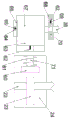
FIG. 1 is a schematic view of the overall structure of a device for drilling and polishing wood boards and recycling the wood boards according to the present invention;
FIG. 2 is a schematic view of the structure in the direction "A-A" of FIG. 1;
FIG. 3 is an enlarged view of the structure at "B" in FIG. 1;
FIG. 4 is an enlarged view of the structure at "C" of FIG. 1;
FIG. 5 is an enlarged view of the structure at "D" of FIG. 1;
FIG. 6 is an enlarged view of the structure at "E" in FIG. 1;
fig. 7 is an enlarged schematic view of the structure at "F" of fig. 1.
Detailed Description
The invention will now be described in detail with reference to fig. 1 to 7, for the sake of convenience of description, the following orientations are now defined: the up, down, left, right, and front-back directions described below correspond to the up, down, left, right, and front-back directions in the projection relationship of fig. 1 itself.
The invention relates to a device for drilling and polishing wood boards and capable of being recycled, which is mainly applied to wood board drilling work and polishing deburring at the same time, and the invention is further explained by combining the attached drawings of the invention:
the invention relates to equipment for drilling and polishing wood boards and capable of being recycled, which comprises an equipment box body 11, wherein a working cavity 93 is fixedly connected in the equipment box body 11, a processing table 39 is fixedly connected on the lower side end surface of the working cavity 93, a rotating table 56 is fixedly connected on the right side end surface of the working cavity 93, an air gun 55 is rotatably connected on the rotating table 56, an air outlet pipe 54 is fixedly connected on the air gun 55, a transmission cavity 43 is fixedly connected on the upper side end wall of the equipment box body 11, a drilling device 101 is arranged in the transmission cavity 43, the drilling device 101 is used for drilling the wood boards, the drilling device 101 comprises a working motor 46 which is slidably connected on the front side end surface of the transmission cavity 43, a lifting hydraulic cylinder 41 is fixedly connected on the lower side end surface of the transmission cavity 43, a supporting block 45 is fixedly connected on the upper side end surface of the lifting hydraulic cylinder 41, and, a first tensioning rope 47 is fixedly connected to an upper end face of the working motor 46, a working motor shaft 42 extending downward is dynamically connected to a lower end face of the working motor 46, a drill bit 40 is fixedly connected to a lower end face of the working motor shaft 42, the drill bit 40 is located above the working cavity 93, a movable cavity 14 is fixedly connected to a lower end wall of the equipment box 11, a polishing device 102 is arranged in the movable cavity 14, the polishing device 102 is used for polishing a hole site after drilling, a movable shaft 52 is arranged in the polishing device 102, a first pinion 53 is fixedly connected to the movable shaft 52, a first main gear 44 is fixedly connected to the working motor shaft 42, the first main gear 44 and the first pinion 53 can be connected in a meshing manner, the drilling device 101 can transmit power to the polishing device 102 for polishing through the meshing connection of the first main gear 44 and the first pinion 53, working chamber 93 left side terminal surface fixedly connected with retrieves chamber 37, retrieve and be equipped with recovery unit 103 in the chamber 37, recovery unit 103 is used for the saw-dust to retrieve.
Advantageously, the polishing device 102 includes a first moving chamber 78 fixedly connected to the upper and lower end surfaces of the transmission chamber 43 and vertically symmetrical, which is specifically described in the above first moving chamber 78 for the sake of brevity, a sliding shaft sleeve 76 is slidably connected in the first moving chamber 78, the first tensioning rope 47 is fixedly connected to the right end surface of the sliding shaft sleeve 76, a first spring 77 is fixedly connected between the right end surface of the sliding shaft sleeve 76 and the right end surface of the first moving chamber 78, the lower end surface of the sliding shaft sleeve 76 is rotatably connected to the downwardly extending movable shaft 52, the first pinion 53 is fixedly connected to the movable shaft 52, the first pinion 53 is meshably connected to the first main gear 44, the first pulley 48 is fixedly connected to the movable shaft 52, the downwardly extending transmission shaft 12 is rotatably connected to the upper end surface of the transmission chamber 43, a first secondary pulley 51 is fixedly connected to the transmission shaft 12, an elastic V-belt 49 is rotatably connected between the first secondary pulley 51 and the first pulley 48, a centrifugal wheel 81 is fixedly connected to the transmission shaft 12, a trigger cavity 57 is fixedly connected to the right end wall of the equipment box 11, the centrifugal wheel 81 is located in the trigger cavity 57, a centrifugal block 80 is slidably connected to the centrifugal wheel 81, a centrifugal spring 79 is fixedly connected between the centrifugal block 80 and the centrifugal wheel 81, a trigger block 82 is slidably connected to the right end face of the trigger cavity 57, a second tensioning rope 84 is fixedly connected to the right end face of the trigger block 82, a trigger spring 83 is fixedly connected between the right end face of the trigger block 82 and the right end face of the trigger cavity 57, a placement cavity 58 is fixedly connected to the rear end wall of the equipment box 11, and an air pump 59 is fixedly connected to the lower end face of the placement cavity 58, the air outlet pipe 54 is fixedly connected to the upper end face of the air pump 59, the button 85 is fixedly connected to the right end face of the air pump 59, the second moving cavity 88 is fixedly connected to the right end face of the placing cavity 58, the pressing block 86 is slidably connected to the second moving cavity 88, the second tensioning rope 84 is fixedly connected to the upper end face of the pressing block 86, and the second spring 87 is fixedly connected between the upper end face of the pressing block 86 and the upper end face of the second moving cavity 88.
Beneficially, a second belt pulley 50 is fixedly connected to the transmission shaft 12, an auxiliary shaft 16 extending upwards is rotatably connected to a lower side end surface of the movable cavity 14, a second secondary belt pulley 15 is fixedly connected to the auxiliary shaft 16, a second V-belt 13 is rotatably connected between the second secondary belt pulley 15 and the second belt pulley 50, a second main gear 17 is fixedly connected to the auxiliary shaft 16, a support rod 20 is fixedly connected to a left side end surface of the movable cavity 14, a shaft sleeve 19 is fixedly connected to a right side end surface of the support rod 20, a grinding shaft 18 is slidably connected to the shaft sleeve 19, a second secondary gear 21 is fixedly connected to the grinding shaft 18, the second secondary gear 21 is in meshing connection with the second main gear 17, a sliding groove wheel 94 is fixedly connected to the grinding shaft 18, a sliding sleeve 90 is rotatably connected to the grinding shaft 18, and a sliding rod 91 is slidably connected to a left side end surface of the movable cavity 14, the right side end face of the sliding rod 91 is fixedly connected with the sliding sleeve 90, the right side end face of the sliding sleeve 90 is fixedly connected with a sliding rod 89, the sliding rod 89 is connected in the sliding groove wheel 94 in a sliding mode, the upper side end face of the grinding shaft 18 is fixedly connected with a grinding wheel 92, and the grinding wheel 92 is located on the lower side of the working cavity 93.
Beneficially, the recycling device 103 comprises an auxiliary chamber 29 fixedly connected to the left end wall of the equipment cabinet 11, an auxiliary motor 26 is fixedly connected to the front end face of the auxiliary chamber 29, an auxiliary motor shaft 27 extending left and right is connected to the auxiliary motor 26 through power, a third belt pulley 28 is fixedly connected to the left end face of the auxiliary motor shaft 27, a dust suction shaft 32 extending right is rotatably connected to the left end face of the auxiliary chamber 29, a third belt pulley 31 is fixedly connected to the dust suction shaft 32, a third V-belt 30 is rotatably connected between the third belt pulley 31 and the third belt pulley 28, a fan 34 is fixedly connected to the dust suction shaft 32, the fan 34 is located in the recycling chamber 37, a scraper 36 is fixedly connected to the right end face of the dust suction shaft 32, an exhaust port 33 is fixedly connected to the left end face of the recycling chamber 37, and a filter screen 35 is fixedly connected to the inner end face of the, the filter screen 35 is located between the fan 34 and the scraper 36, and a recovery pipe 38 is fixedly connected to the lower end face of the recovery cavity 37.
Advantageously, a main bevel gear 72 is slidably connected to the auxiliary motor shaft 27, a sliding cavity 73 is fixedly connected to the upper end surface of the auxiliary cavity 29, a moving rod 74 is slidably connected to the sliding cavity 73, the moving rod 74 is rotatably connected to the right end surface of the main bevel gear 72, a fourth tensioning rope 65 is fixedly connected to the right end surface of the moving rod 74, a pushing spring 75 is fixedly connected between the right end surface of the moving rod 74 and the right end surface of the sliding cavity 73, a downward extending extrusion shaft 22 is rotatably connected to the lower end surface of the auxiliary cavity 29, a secondary bevel gear 25 is fixedly connected to the upper end surface of the extrusion shaft 22, the secondary bevel gear 25 is in meshing connection with the main bevel gear 72, a cam 23 is fixedly connected to the extrusion shaft 22, a extrusion cavity 24 is fixedly connected to the lower end wall of the equipment box 11, and the cam 23 is located in the extrusion cavity 24, a piston rod 71 is slidably connected to the front end face of the extrusion cavity 24, a pressing plate 60 is fixedly connected to the rear end face of the piston rod 71, the cam 23 rotates to abut against the pressing plate 60, a return spring 61 is fixedly connected between the front end face of the pressing plate 60 and the front end face of the extrusion cavity 24, a pressing plate 63 is fixedly connected to the front end face of the piston rod 71, a collecting cavity 67 is fixedly connected to the lower end wall of the equipment box 11, the collecting cavity 67 is located at the front side of the extrusion cavity 24, the pressing plate 63 is slidably connected in the collecting cavity 67, a third tensioning rope 62 is fixedly connected to the rear end face of the pressing plate 63, a pressure plate 66 is slidably connected to the lower end face of the collecting cavity 67, a fourth tensioning rope 65 is fixedly connected to the lower end face of the pressure plate 66, and a pressure spring 64 is fixedly connected between the lower end face of the pressure plate 66, the recovery tube 38 is fixedly connected to the upper end face of the collection cavity 67, the lower end wall of the equipment box 11 is fixedly connected to a third movable cavity 69, the third movable cavity 69 is located on the upper side of the collection cavity 67, a partition plate 70 is slidably connected to the third movable cavity 69, the partition plate 70 is slidably connected to the recovery tube 38, the third tensioning rope 62 is fixedly connected to the front end face of the partition plate 70, and a third spring 68 is fixedly connected between the front end face of the partition plate 70 and the front end face of the third movable cavity 69.
The following describes in detail the use steps of the apparatus for drilling and polishing and recycling wood boards according to the present disclosure with reference to fig. 1 to 7:
to begin with, the first tensioning cord 47 is in a tensioned state, the first spring 77 is in a tensioned state, the first pinion 53 is not engaged with the first main gear 44, the centrifugal spring 79 is in a normal state, the second tensioning cord 84 is in a tensioned state, the trigger spring 83 is in a tensioned state, the second spring 87 is in a compressed state, the main bevel gear 72 is not engaged with the secondary bevel gear 25, the fourth tensioning cord 65 is in a tensioned state, the push spring 75 is in a compressed state, the pressure spring 64 is in a tensioned state, the return spring 61 is in a normal state, the third tensioning cord 62 is in a tensioned state, the third spring 68 is in a tensioned state, and the partition 70 is connected to the recovery pipe 38.
The device starts to work, a wood board is placed on the upper side of the processing table 39 to be fixed, drilling processing is prepared, the working motor 46 is started, the working motor 46 drives the working motor shaft 42 to rotate, the working motor shaft 42 drives the drill bit 40 to rotate, meanwhile, the lifting hydraulic cylinder 41 is started, the lifting hydraulic cylinder 41 is connected through the supporting block 45 to drive the working motor 46 to move downwards, so as to drive the drill bit 40 to move downwards, drilling is carried out on the wood board, meanwhile, the first tensioning rope 47 is in a tensioning state, the first spring 77 is in a compression state, the first tensioning rope 47 drives the sliding shaft sleeve 76 to move rightwards, the sliding shaft sleeve 76 is connected through the movable shaft 52 to drive the first pinion 53 to move rightwards, and therefore, when the drill bit 40 moves downwards, the first main gear 44 is not meshed with the first pinion 53, after the drill 40 finishes drilling, the hydraulic lifting cylinder 41 moves upwards to drive the drill 40 to return upwards, the first tensioning rope 47 returns to a loose state, the first spring 77 returns to a stretched state, the first pinion 53 moves leftwards to return, and meanwhile, when the first main gear 44 returns from bottom to top, the first main gear 44 is meshed with the first pinion 53, so that polishing treatment is performed.
When the first main gear 44 is reset from bottom to top, the first main gear 44 is meshed with the first secondary gear 53, the working motor shaft 42 drives the first main gear 44 to rotate, the first main gear 44 drives the first secondary gear 53 to rotate, the first secondary gear 53 drives the movable shaft 52 to rotate, the movable shaft 52 drives the first pulley 48 to rotate, the first pulley 48 is connected to drive the first secondary pulley 51 to rotate through the elastic V-belt 49, the first secondary pulley 51 drives the transmission shaft 12 to rotate, the transmission shaft 12 drives the second pulley 50 to rotate, the second pulley 50 is connected to drive the second secondary pulley 15 to rotate through the second V-belt 13, the second secondary pulley 15 drives the auxiliary shaft 16 to rotate, the auxiliary shaft 16 drives the second main gear 17 to rotate, and the second main gear 17 drives the second secondary gear 21 to rotate, the second auxiliary gear 21 drives the grinding shaft 18 to rotate, the grinding shaft 18 drives the grinding wheel 92 to rotate, meanwhile, the grinding shaft 18 drives the sliding groove wheel 94 to rotate, the sliding groove wheel 94 drives the sliding rod 89 to reciprocate up and down, the sliding rod 89 is connected with and drives the grinding wheel 92 to reciprocate up and down through the sliding sleeve 90, so that the grinding wheel 92 rotates and reciprocates up and down simultaneously, the hole site processed by the drill bit 40 is ground, surface burrs are removed, the overall roughness of the hole site is improved, when the first main gear 44 continues to move upwards to reset, and when the first auxiliary gear 53 is moved away, the grinding wheel 92 completes one-time reciprocating motion to finish grinding work, thereby realizing synchronous drilling and grinding operation, reducing secondary operation and improving overall working efficiency.
When the transmission shaft 12 rotates, the transmission shaft 12 drives the centrifugal wheel 81 to rotate, the centrifugal wheel 81 rotates to generate centrifugal force, the centrifugal block 80 is driven to rotate and be thrown outwards, the centrifugal spring 79 becomes a tensile state, the centrifugal block 80 rotates to abut against the trigger block 82, the trigger spring 83 becomes a compression state, the second tensioning rope 84 becomes a tension state, the second spring 87 becomes a tensile state, the second spring 87 drives the trigger block 86 to move downwards, the second spring 87 abuts against the button 85, the air pump 59 performs single operation, air flow is conveyed to the air gun 55 through the air outlet pipe 54, the air gun 55 cleans wood chips on the processing table 39, and subsequent drilling influence is reduced and wood chip recovery work is performed.
The auxiliary motor 26 is started, the auxiliary motor 26 drives the auxiliary motor shaft 27 to rotate, the auxiliary motor shaft 27 drives the third belt pulley 28 to rotate, the third belt pulley 28 is connected with and drives the third secondary belt pulley 31 to rotate through the third V belt 30, the third secondary belt pulley 31 drives the dust suction shaft 32 to rotate, the dust suction shaft 32 drives the fan 34 to rotate, the fan 34 rotates to generate negative pressure to absorb the wood chips removed from the working chamber 93, the wood chips enter the recovery chamber 37, the filter screen 35 filters the wood chips, the dust suction shaft 32 drives the scraper 36 to rotate, the scraper 36 rotates to scrape off the wood chips filtered out from the filter screen 35, the scraped wood chips are conveyed to the collection chamber 67 through the recovery pipe 38 to be collected, and after the wood chips in the collection chamber 67 reach a certain quality, the weight of wood chips presses the pressure plate 66 downwards, the pressure spring 64 becomes a compressed state, the fourth tensioning rope 65 becomes a loosened state, the pushing spring 75 becomes a stretched state, the pushing spring 75 is connected through the moving rod 74 to drive the main bevel gear 72 to move leftwards, the main bevel gear 72 is meshed with the secondary bevel gear 25, the auxiliary motor shaft 27 drives the main bevel gear 72 to rotate, the main bevel gear 72 drives the secondary bevel gear 25 to rotate, the secondary bevel gear 25 drives the extrusion shaft 22 to rotate, the extrusion shaft 22 drives the cam 23 to rotate, the cam 23 rotates to abut against the contact pressure plate 60 to drive the contact pressure plate 60 to move forwards, the return spring 61 becomes a compressed state, the contact pressure plate 60 is connected through the piston rod 71 to drive the extrusion plate 63 to move forwards, and the third tensioning rope 62 becomes a tensioned state, the third spring 68 is in a compressed state, the third tensioning rope 62 drives the partition plate 70 to move forward, the partition plate 70 is disconnected from the recovery pipe 38, wood chips in the recovery pipe 38 stop entering the collection cavity 67, the wood chips in the collection cavity 67 are conveniently extruded, the extrusion plate 63 moves forward to extrude the wood chips in the collection cavity 67, the wood chips are prevented from flying around, the wood chips are extruded into blocks, and therefore people can conveniently recover and carry the wood chips.
The invention has the beneficial effects that: the equipment for drilling and polishing the wood board and capable of being recycled can drill the wood board and remove burrs of the wood board, meanwhile, wood chips generated by machining are collected and recycled, the drill bit is driven to rotate by the motor and is driven to move up and down by the hydraulic cylinder, the drill bit can complete drilling operation on the wood board downwards, when the drill bit is reset upwards, the transition gear can be triggered to rotate, so that power of the motor is transmitted, the polishing wheel is driven to polish the wood board hole positions correspondingly completed, surface burrs are removed, the overall roughness is improved, the air gun is driven to clear the wood chips on the workbench, the fan is used for recycling, the cam structure can be started to move after the recycled wood chips reach a certain quality, the wood chips are extruded and formed in the collecting cavity, and accordingly recycling and carrying are facilitated.
In the above manner, a person skilled in the art can make various changes depending on the operation mode within the scope of the present invention.
Claims (5)
1. The utility model provides a but be used for plank drilling and polish recycle's equipment, includes the equipment box, its characterized in that: the wood board drilling device is characterized in that a working cavity is fixedly connected in the equipment box body, a machining table is fixedly connected to the lower side end face of the working cavity, a rotating table is fixedly connected to the right side end face of the working cavity, an air gun is rotatably connected to the rotating table, an air outlet pipe is fixedly connected to the air gun, a transmission cavity is fixedly connected to the upper side end wall of the equipment box body, a drilling device is arranged in the transmission cavity and used for drilling wood boards, the drilling device comprises a working motor which is slidably connected to the front end face of the transmission cavity, a lifting hydraulic cylinder is fixedly connected to the lower side end face of the transmission cavity, a supporting block is fixedly connected to the upper side end face of the lifting hydraulic cylinder, the working motor is fixedly connected to the right side end face of the supporting block, a first tensioning rope is fixedly, the utility model discloses a grinding device, including work motor shaft, working chamber, equipment box, grinding device, drilling device.
2. A device for the drilling and sanding of wooden boards and for recycling, as claimed in claim 1, characterized in that: the polishing device comprises a first moving cavity which is fixedly connected with the upper end surface and the lower end surface of the transmission cavity and is symmetrical up and down, for the following brief description, the first moving cavity on the upper side is described in detail, a sliding shaft sleeve is connected in a sliding manner in the first moving cavity, the first tensioning rope is fixedly connected with the right end surface of the sliding shaft sleeve, a first spring is fixedly connected between the right end surface of the sliding shaft sleeve and the right end surface of the first moving cavity, the lower end surface of the sliding shaft sleeve is rotatably connected with the movable shaft which extends downwards, the movable shaft is fixedly connected with a first auxiliary gear, the first auxiliary gear and the first main gear can be meshed and connected, the movable shaft is fixedly connected with a first belt pulley, the upper end surface of the transmission cavity is rotatably connected with a transmission shaft which extends downwards, and the transmission shaft is fixedly connected with a first auxiliary belt pulley, an elastic V-belt is rotatably connected between the first auxiliary belt wheel and the first belt wheel, a centrifugal wheel is fixedly connected on the transmission shaft, a trigger cavity is fixedly connected on the right side end wall of the equipment box body, the centrifugal wheel is positioned in the trigger cavity, a centrifugal block is slidably connected on the centrifugal wheel, a centrifugal spring is fixedly connected between the centrifugal block and the centrifugal wheel, a trigger block is slidably connected on the right side end surface of the trigger cavity, a second tensioning rope is fixedly connected on the right side end surface of the trigger block, a trigger spring is fixedly connected between the right side end surface of the trigger block and the right side end surface of the trigger cavity, a placing cavity is fixedly connected on the rear side end wall of the equipment box body, an air pump is fixedly connected on the lower side end surface of the placing cavity, the air outlet pipe is fixedly connected on the upper side end surface of the air pump, a button is fixedly connected on the right side end, the second movable cavity is internally and slidably connected with a touch block, the upper end face of the touch block is fixedly connected with the second tensioning rope, and a second spring is fixedly connected between the upper end face of the touch block and the upper end face of the second movable cavity.
3. A device for the drilling and sanding of wooden boards and for recycling, as claimed in claim 2, characterized in that: the transmission shaft is fixedly connected with a second belt wheel, the lower side end face of the movable cavity is rotatably connected with an auxiliary shaft extending upwards, the auxiliary shaft is fixedly connected with a second auxiliary belt wheel, a second V belt is rotatably connected between the second auxiliary belt wheel and the second belt wheel, a second main gear is fixedly connected on the auxiliary shaft, the left side end face of the movable cavity is fixedly connected with a supporting rod, the right side end face of the supporting rod is fixedly connected with a shaft sleeve, a polishing shaft is slidably connected in the shaft sleeve, a second auxiliary gear is fixedly connected on the polishing shaft, the second auxiliary gear is meshed with the second main gear, a sliding groove wheel is fixedly connected on the polishing shaft, a sliding sleeve is rotatably connected on the polishing shaft, the left side end face of the movable cavity is slidably connected with a sliding rod, the right side end face of the sliding rod is fixedly connected with the sliding sleeve, and the right side end face of the, the sliding rod is connected in the sliding groove wheel in a sliding mode, a polishing wheel is fixedly connected to the end face of the upper side of the polishing shaft, and the polishing wheel is located on the lower side of the working cavity.
4. A device for the drilling and sanding of wooden boards and for recycling, as claimed in claim 1, characterized in that: the recovery device comprises an auxiliary cavity fixedly connected with the left end wall of the equipment box body, an auxiliary motor is fixedly connected with the front end face of the auxiliary cavity, the auxiliary motor is connected with an auxiliary motor shaft which extends left and right in a power mode, the left end face of the auxiliary motor shaft is fixedly connected with a third belt wheel, the left end surface of the auxiliary cavity is rotationally connected with a dust absorption shaft extending rightwards, the dust absorption shaft is fixedly connected with a third auxiliary belt wheel, a third V-belt is rotatably connected between the third secondary belt wheel and the third belt wheel, a fan is fixedly connected on the dust absorption shaft, the fan is positioned in the recovery cavity, the end surface of the right side of the dust absorption shaft is fixedly connected with a scraper, the end surface of the left side of the recovery cavity is fixedly connected with an exhaust port, the side end face of the recycling cavity is fixedly connected with a filter screen, the filter screen is positioned between the fan and the scraping plates, and the side end face of the recycling cavity is fixedly connected with a recycling pipe.
5. The apparatus for wood board drilling and grinding and recycling as claimed in claim 4, wherein: a main bevel gear is connected to the shaft of the auxiliary motor in a sliding manner, a sliding cavity is fixedly connected to the upper end face of the auxiliary cavity, a moving rod is connected to the sliding cavity in a sliding manner, the right end face of the main bevel gear is connected with the moving rod in a rotating manner, a fourth tensioning rope is fixedly connected to the right end face of the moving rod, a pushing spring is fixedly connected between the right end face of the moving rod and the right end face of the sliding cavity, a downward extending extrusion shaft is connected to the lower end face of the auxiliary cavity in a rotating manner, an auxiliary bevel gear is fixedly connected to the upper end face of the extrusion shaft, the auxiliary bevel gear and the main bevel gear can be meshed and connected with each other, a cam is fixedly connected to the extrusion shaft, an extrusion cavity is fixedly connected to the lower end wall of the equipment box body, the cam is located in the extrusion cavity, a piston rod is connected, the cam can abut against the touch plate in a rotating manner, a reset spring is fixedly connected between the front end face of the touch plate and the front end face of the extrusion cavity, the front end face of the piston rod is fixedly connected with an extrusion plate, the lower side end wall of the equipment box body is fixedly connected with a collection cavity, the collection cavity is positioned on the front side of the extrusion cavity, the extrusion plate is connected in the collection cavity in a sliding manner, the rear end face of the extrusion plate is fixedly connected with a third tensioning rope, the lower side end face of the collection cavity is connected with a pressure plate in a sliding manner, the lower side end face of the pressure plate is fixedly connected with a fourth tensioning rope, a pressure spring is fixedly connected between the lower side end face of the pressure plate and the lower side end face of the collection cavity, the upper side end face of the collection cavity is fixedly connected with the recovery tube, the lower side end wall, the third movable cavity is internally and slidably connected with a partition plate, the partition plate is slidably connected in the recovery pipe, the front end face of the partition plate is fixedly connected with the third tensioning rope, and a third spring is fixedly connected between the front end face of the partition plate and the front end face of the third movable cavity.
Priority Applications (1)
| Application Number | Priority Date | Filing Date | Title |
|---|---|---|---|
| CN202110057809.8A CN112621910A (en) | 2021-01-15 | 2021-01-15 | A but, equipment that is used for plank drilling and polishes and recycle |
Applications Claiming Priority (1)
| Application Number | Priority Date | Filing Date | Title |
|---|---|---|---|
| CN202110057809.8A CN112621910A (en) | 2021-01-15 | 2021-01-15 | A but, equipment that is used for plank drilling and polishes and recycle |
Publications (1)
| Publication Number | Publication Date |
|---|---|
| CN112621910A true CN112621910A (en) | 2021-04-09 |
Family
ID=75294378
Family Applications (1)
| Application Number | Title | Priority Date | Filing Date |
|---|---|---|---|
| CN202110057809.8A Withdrawn CN112621910A (en) | 2021-01-15 | 2021-01-15 | A but, equipment that is used for plank drilling and polishes and recycle |
Country Status (1)
| Country | Link |
|---|---|
| CN (1) | CN112621910A (en) |
Cited By (4)
| Publication number | Priority date | Publication date | Assignee | Title |
|---|---|---|---|---|
| CN113601616A (en) * | 2021-08-12 | 2021-11-05 | 胡赞鹏 | Integral type equipment of polishing with equidistance drilling function |
| CN113696282A (en) * | 2021-08-12 | 2021-11-26 | 陈国文 | Stable drilling and polishing integrated equidistant drilling equipment |
| CN114260984A (en) * | 2021-12-28 | 2022-04-01 | 刘燕辉 | Furniture board center drilling and polishing integrated machine |
| CN117484609A (en) * | 2022-07-25 | 2024-02-02 | 赣州晨品家具有限公司 | A plate drilling device for furniture processing |
Citations (8)
| Publication number | Priority date | Publication date | Assignee | Title |
|---|---|---|---|---|
| CN106827124A (en) * | 2016-12-21 | 2017-06-13 | 重庆金华兴门业有限公司 | Timber removes scar device |
| CN110450023A (en) * | 2019-08-05 | 2019-11-15 | 义乌市拓一斯玩具有限公司 | Drilling and polishing device for wooden crafts and polishing method thereof |
| CN111002053A (en) * | 2020-01-14 | 2020-04-14 | 东阳故宏机械科技有限公司 | A machine base that collects cutting chips |
| CN211030364U (en) * | 2019-10-28 | 2020-07-17 | 群升门窗股份有限公司 | A kind of wooden household door panel punching device |
| CN211590476U (en) * | 2020-01-16 | 2020-09-29 | 四川农业大学 | Drilling equipment for furniture manufacturing |
| CN111872700A (en) * | 2020-09-17 | 2020-11-03 | 台州椒江扣纳离心机科技有限公司 | Movable multifunctional equipment that polishes and can cut |
| CN112025866A (en) * | 2020-09-16 | 2020-12-04 | 东阳潘辰竹木工艺品有限公司 | Can clear up saw-dust and sculpture equipment that can polish |
| CN112060216A (en) * | 2020-09-18 | 2020-12-11 | 温岭云歌工艺品有限公司 | Three-dimensional wood carving equipment capable of collecting wood chips |
-
2021
- 2021-01-15 CN CN202110057809.8A patent/CN112621910A/en not_active Withdrawn
Patent Citations (8)
| Publication number | Priority date | Publication date | Assignee | Title |
|---|---|---|---|---|
| CN106827124A (en) * | 2016-12-21 | 2017-06-13 | 重庆金华兴门业有限公司 | Timber removes scar device |
| CN110450023A (en) * | 2019-08-05 | 2019-11-15 | 义乌市拓一斯玩具有限公司 | Drilling and polishing device for wooden crafts and polishing method thereof |
| CN211030364U (en) * | 2019-10-28 | 2020-07-17 | 群升门窗股份有限公司 | A kind of wooden household door panel punching device |
| CN111002053A (en) * | 2020-01-14 | 2020-04-14 | 东阳故宏机械科技有限公司 | A machine base that collects cutting chips |
| CN211590476U (en) * | 2020-01-16 | 2020-09-29 | 四川农业大学 | Drilling equipment for furniture manufacturing |
| CN112025866A (en) * | 2020-09-16 | 2020-12-04 | 东阳潘辰竹木工艺品有限公司 | Can clear up saw-dust and sculpture equipment that can polish |
| CN111872700A (en) * | 2020-09-17 | 2020-11-03 | 台州椒江扣纳离心机科技有限公司 | Movable multifunctional equipment that polishes and can cut |
| CN112060216A (en) * | 2020-09-18 | 2020-12-11 | 温岭云歌工艺品有限公司 | Three-dimensional wood carving equipment capable of collecting wood chips |
Cited By (5)
| Publication number | Priority date | Publication date | Assignee | Title |
|---|---|---|---|---|
| CN113601616A (en) * | 2021-08-12 | 2021-11-05 | 胡赞鹏 | Integral type equipment of polishing with equidistance drilling function |
| CN113696282A (en) * | 2021-08-12 | 2021-11-26 | 陈国文 | Stable drilling and polishing integrated equidistant drilling equipment |
| CN114260984A (en) * | 2021-12-28 | 2022-04-01 | 刘燕辉 | Furniture board center drilling and polishing integrated machine |
| CN117484609A (en) * | 2022-07-25 | 2024-02-02 | 赣州晨品家具有限公司 | A plate drilling device for furniture processing |
| CN117484609B (en) * | 2022-07-25 | 2025-11-21 | 赣州晨品家具有限公司 | Board drilling device for furniture processing |
Similar Documents
| Publication | Publication Date | Title |
|---|---|---|
| CN113352163A (en) | Furniture manufacturing wood board cutting surface polishing device and method | |
| CN111496896B (en) | A PVC pipe cutting and drilling device | |
| CN208179804U (en) | Multifunctional plate handles mechanical equipment | |
| CN112643086A (en) | Metal engraving equipment capable of recycling waste metal and achieving environment-friendly utilization | |
| CN108857693A (en) | A kind of highly-efficient glass edge polisher | |
| CN108838872B (en) | Timber grinding device | |
| CN112677251A (en) | Drilling machine for dust-free woodworking for high-grade furniture and processing technology thereof | |
| CN112108883A (en) | Adjustable automatic cutting and polishing equipment for alloy pipeline | |
| CN112025866A (en) | Can clear up saw-dust and sculpture equipment that can polish | |
| CN112338665A (en) | Equipment for grinding and polishing stone slab and recycling stone powder | |
| CN108500801B (en) | Gear processing device for transmission | |
| CN112454054A (en) | Equipment capable of adjusting angle for cutting underground water pipe | |
| CN216265006U (en) | Scrap cleaning structure for surface grinding machine machining die carrier | |
| CN112578887A (en) | Auxiliary equipment for heat dissipation and ash removal of notebook computer | |
| CN111761657A (en) | Handheld timber perforating device | |
| CN219747222U (en) | Piece cleaning equipment for milling machine machining center | |
| CN111805329B (en) | Timber equipment of polishing | |
| CN220161310U (en) | Workpiece turning tool | |
| CN111844251A (en) | Perforator for punching and automatically tapping on wood board | |
| CN218504195U (en) | Polishing device for cylindrical roller bearing of rolling mill | |
| CN115781826A (en) | Processing device and processing method of bamboo chip tray | |
| CN215038299U (en) | Furniture processing is with sculpture workstation that dust absorbs | |
| CN209532867U (en) | A drilling chip cleaning device | |
| CN220218600U (en) | Spraying dust fall type cutting machine capable of collecting and processing scouring scraps | |
| CN111604725A (en) | Precious timber cup inner wall sculpture grinding device |
Legal Events
| Date | Code | Title | Description |
|---|---|---|---|
| PB01 | Publication | ||
| PB01 | Publication | ||
| SE01 | Entry into force of request for substantive examination | ||
| SE01 | Entry into force of request for substantive examination | ||
| WW01 | Invention patent application withdrawn after publication |
Application publication date: 20210409 |
|
| WW01 | Invention patent application withdrawn after publication |