Axial drawing processing equipment and method for thin-wall slender shaft parts
Technical Field
The invention relates to the technical field of machining, in particular to axial stretching machining equipment and method for thin-wall slender shaft parts.
Background
With the development of aeroengine materials and manufacturing technologies towards the direction of compositing, light weight, integration, high efficiency and low cost, the engine parts are lighter and lighter, and because the parts are mostly thin-wall slender shaft parts, on one hand, because the parts are slender and have poor rigidity, radial cutting force is easy to cause bending deformation of the parts and vibration during processing, and the processing precision and roughness are influenced; on the other hand, the thickness of the wall is very thin, the rigidity is poor, and the wall is easy to deform under the action of clamping force and radial cutting force, so that the cutting depth is uneven and the phenomenon of cutter back-off is caused. How to better improve the rigidity of parts and effectively avoid the problems of processing deformation and poor wall thickness during processing is an important difficulty in processing thin-wall slender shaft parts at present.
Disclosure of Invention
In order to overcome the defects of the prior art, the invention aims to provide the axial drawing processing equipment and method for the thin-wall slender shaft parts, which not only improve the cutting performance, but also effectively prevent the processing deformation.
In order to achieve the purpose, the invention is realized by the following technical scheme:
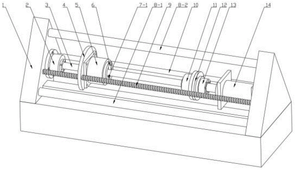
an axial stretching processing device for thin-wall slender shaft parts comprises a base 1, wherein a left hydraulic chuck 2 is fixed on the inner side of a left supporting surface of the base 1, the thin-wall slender shaft parts 3 are clamped by the left hydraulic chuck 2 and a right hydraulic chuck 11, the right hydraulic chuck 11 is installed on the left side of a sensor connecting piece 12, a tension and compression sensor 13 is installed on the right side of the sensor connecting piece 12, the tension and compression sensor 13 is connected to the head of a hydraulic cylinder 14, the bottom of the hydraulic cylinder 14 is fixed on the right supporting surface of the base 1, and the axial stretching of the thin-wall slender shaft parts 3 is realized;
a ball screw 9 and a driven shaft 10 are connected between the left supporting surface and the right supporting surface of the base 1, a motor fixing seat 4 is connected on the ball screw 9 and the driven shaft 10, the bottom of the motor fixing seat 4 is matched with a sliding rail of the base 1, a disc type motor 5 is installed on the motor fixing seat 4, turning tools 6, a first supporting roller 7-1 and a second supporting roller 7-2 are uniformly installed on a rotating disc of the disc type motor 5, and the turning tools 6, the first supporting roller 7-1 and the second supporting roller 7-2 are in contact with the thin-wall slender shaft part 3; the first supporting roller 7-1 and the second supporting roller 7-2 can freely rotate in the head sphere, and radial feeding is realized through threads.
A first upright post 8-1, a second upright post 8-2 and a third upright post 8-3 are connected between the left and right supporting surfaces at the upper part of the base 1.
The processing method based on the axial stretching processing equipment for the thin-wall slender shaft parts comprises the following steps:
step A, blanking, and processing the inner hole of the thin-wall slender shaft part 3 in place according to requirements;
b, pre-stretching for the first time, namely installing the thin-wall slender shaft type part 3 with the processed inner hole on equipment for axial stretching, and controlling the stretching force through a tension and compression sensor 13;
c, roughly processing prestress, keeping the prestress, and preliminarily processing the appearance structure of the thin-wall slender shaft type part 3 according to requirements;
d, performing second pre-stretching, namely axially stretching the thin-wall slender shaft type part 3, and controlling the stretching force through a tension and compression sensor 13;
e, performing prestress semi-finishing, keeping prestress, and further processing the appearance structure of the thin-wall slender shaft type part 3 according to requirements;
step F, performing pre-stretching for the third time, axially stretching the thin-wall slender shaft type part 3, and controlling the stretching force through a tension and compression sensor 13;
and G, performing prestress finish machining, keeping prestress, and performing finish machining on the appearance structure of the thin-wall slender shaft type part 3 according to requirements.
The pretension force or prestressing force F in said step B, C, E, G satisfies the following formula:
F=α·Q·A
wherein alpha is a pre-stretching or pre-stress coefficient; q is the yield strength of the thin-wall slender shaft part material; a is the cross-sectional area of the thin-wall slender shaft part.
The invention has the beneficial effects that: in the machining process, the turning tool and the support roller simultaneously support the thin-wall slender shaft part, so that the rigidity of the thin-wall slender shaft part is enhanced, the machining deformation of the thin-wall slender shaft part caused by radial cutting force is reduced, and the quality of a machined product is improved; meanwhile, the prestress is kept in the machining process, and the distribution condition of residual stress is improved by adopting the process methods of pre-stretching, rough machining, pre-stretching, semi-finishing, pre-stretching and finishing under the condition of keeping the process state of the thin-wall slender shaft type part, so that the cutting performance is improved, and the machining deformation is effectively prevented.
Drawings
Figure 1 is an isometric view of the apparatus of the present invention in one orientation.
Figure 2 is an isometric view of the apparatus of the present invention in another orientation.
Fig. 3 is a schematic view of the installation of the disc motor of the device of the invention.
FIG. 4 is a pre-tensioning force loading schematic of the method of the present invention.
Detailed Description
The technical solutions of the present invention are further described below with reference to the drawings and examples, but the scope of the claims is not limited thereto.
As shown in fig. 1 and 2, an axial drawing processing device for thin-wall slender shaft parts comprises a base 1, wherein a first upright post 8-1, a second upright post 8-2 and a third upright post 8-3 are connected between a left supporting surface and a right supporting surface at the upper part of the base 1, and the rigidity of the device is enhanced by the three upright posts; a left hydraulic chuck 2 is fixed on the inner side of the left supporting surface through a bolt, the thin-wall slender shaft part 3 is clamped by the left hydraulic chuck 2 and the right hydraulic chuck 11, the right hydraulic chuck 11 is installed on the left side of a sensor connecting piece 12, a tension and compression sensor 13 is installed on the right side of the sensor connecting piece 12, the tension and compression sensor 13 is connected to the head of a hydraulic cylinder 14, the bottom of the hydraulic cylinder 14 is fixed on the right supporting surface of a base 1 through a bolt, and the axial stretching of the thin-wall slender shaft part 3 is realized through the linear;
a ball screw 9 and a driven shaft 10 are connected between a left supporting surface and a right supporting surface at the upper part of the base 1, a motor fixing seat 4 is connected on the ball screw 9 and the driven shaft 10, the bottom of the motor fixing seat 4 is matched with a sliding rail of the base 1, and the motor fixing seat 4 realizes axial movement on the sliding rail of the base 1 through the ball screw 9 and the driven shaft 10; a disc type motor 5 is arranged on the motor fixing seat 4, as shown in fig. 3, turning tools 6, a first supporting roller 7-1 and a second supporting roller 7-2 are uniformly arranged on a rotating disc of the disc type motor 5, and the turning tools 6, the first supporting roller 7-1 and the second supporting roller 7-2 are in contact with the thin-wall slender shaft type part 3; the spheres at the head parts of the first supporting roller 7-1 and the second supporting roller 7-2 can freely rotate, radial feeding is realized through threads, the turning tool 6, the first supporting roller 7-1 and the second supporting roller 7-2 are driven to rotate through the rotation of the disc motor 5, so that turning is finished, and the machining deformation of the thin-wall slender shaft part 3 caused by radial cutting force is reduced due to the existence of the first supporting roller 7-1 and the second supporting roller 7-2 in the machining process.
Referring to fig. 4, the processing method based on the axial drawing processing equipment for the thin-wall slender shaft parts comprises the following steps:
step A, blanking, and processing the inner hole of the thin-wall slender shaft part 3 in place according to requirements;
b, pre-stretching for the first time, namely installing the thin-wall slender shaft type part 3 with the processed inner hole on equipment for axial stretching, wherein the pre-stretching coefficient is 0.06, and controlling the stretching force through a tension and compression sensor 13;
step C, prestress rough machining is carried out, prestress is kept, the prestress coefficient is 0.02, the disc type motor 5 drives the turning cutter 6 to rotate, the ball screw 9 drives the disc type motor 5 to move axially, and therefore machining of the thin-wall slender shaft type part 3 is achieved, the first supporting roller 7-1 and the second supporting roller 7-2 support the thin-wall slender shaft type part 3 in the machining process, and the appearance structure of the thin-wall slender shaft type part 3 is machined preliminarily according to requirements;
d, performing secondary pre-stretching, namely axially stretching the thin-wall slender shaft type part 3, wherein the pre-stretching coefficient is 0.04, and controlling the stretching force through a tension and compression sensor 13;
e, performing prestress semi-finishing, keeping the prestress, taking the prestress coefficient as 0.02, and further processing the appearance structure of the thin-wall slender shaft type part 3 according to the requirement;
step F, performing pre-stretching for the third time, axially stretching the thin-wall slender shaft type part 3, wherein the pre-stretching coefficient is 0.04, and controlling the stretching force through a tension and compression sensor 13;
and G, performing prestress finish machining, keeping prestress, taking the prestress coefficient as 0.01, and performing finish machining on the appearance structure of the thin-wall slender shaft type part 3 as required.
The pretension force or prestressing force F in said step B, C, E, G satisfies the following formula:
F=α·Q·A
wherein alpha is a pre-stretching or pre-stress coefficient; q is the yield strength of the thin-wall slender shaft part material; a is the cross-sectional area of the thin-wall slender shaft part.
In the machining process, the thin-wall slender shaft parts are supported by the supporting rollers, so that the rigidity of the thin-wall slender shaft parts is enhanced, the machining deformation caused by radial cutting force is reduced, and the machining performance is integrally improved; by adopting the technical methods of pre-stretching, rough machining, pre-stretching, semi-finishing, pre-stretching and finishing, under the condition of keeping the technical state of thin-wall slender shaft parts, the distribution condition of residual stress is improved, thereby improving the cutting performance and effectively preventing the machining deformation.