CN112607922A - Multistage circulating sewage treatment plant - Google Patents
Multistage circulating sewage treatment plant Download PDFInfo
- Publication number
- CN112607922A CN112607922A CN202110060916.6A CN202110060916A CN112607922A CN 112607922 A CN112607922 A CN 112607922A CN 202110060916 A CN202110060916 A CN 202110060916A CN 112607922 A CN112607922 A CN 112607922A
- Authority
- CN
- China
- Prior art keywords
- pipe
- fixed mounting
- flocculation tank
- tank
- fixedly provided
- Prior art date
- Legal status (The legal status is an assumption and is not a legal conclusion. Google has not performed a legal analysis and makes no representation as to the accuracy of the status listed.)
- Pending
Links
- 239000010865 sewage Substances 0.000 title claims abstract description 76
- 238000005189 flocculation Methods 0.000 claims abstract description 94
- 230000016615 flocculation Effects 0.000 claims abstract description 94
- 239000010802 sludge Substances 0.000 claims abstract description 57
- 239000007788 liquid Substances 0.000 claims abstract description 41
- 239000003814 drug Substances 0.000 claims abstract description 38
- 238000003756 stirring Methods 0.000 claims abstract description 28
- 238000004062 sedimentation Methods 0.000 claims abstract description 22
- 238000007599 discharging Methods 0.000 claims abstract description 15
- XLYOFNOQVPJJNP-UHFFFAOYSA-N water Substances O XLYOFNOQVPJJNP-UHFFFAOYSA-N 0.000 claims description 40
- VEXZGXHMUGYJMC-UHFFFAOYSA-M Chloride anion Chemical compound [Cl-] VEXZGXHMUGYJMC-UHFFFAOYSA-M 0.000 claims description 25
- 238000000926 separation method Methods 0.000 claims description 24
- 229920002401 polyacrylamide Polymers 0.000 claims description 22
- 239000003638 chemical reducing agent Substances 0.000 claims description 21
- 230000003014 reinforcing effect Effects 0.000 claims description 7
- 238000003466 welding Methods 0.000 claims 1
- 230000000694 effects Effects 0.000 abstract description 6
- 230000007306 turnover Effects 0.000 abstract description 2
- 230000009286 beneficial effect Effects 0.000 abstract 1
- 238000001802 infusion Methods 0.000 description 13
- 239000000463 material Substances 0.000 description 12
- 238000000034 method Methods 0.000 description 10
- 229940079593 drug Drugs 0.000 description 8
- 239000002131 composite material Substances 0.000 description 5
- VSCWAEJMTAWNJL-UHFFFAOYSA-K aluminium trichloride Chemical compound Cl[Al](Cl)Cl VSCWAEJMTAWNJL-UHFFFAOYSA-K 0.000 description 4
- 239000000203 mixture Substances 0.000 description 3
- 239000000701 coagulant Substances 0.000 description 2
- 230000007547 defect Effects 0.000 description 2
- 239000008394 flocculating agent Substances 0.000 description 2
- 238000004519 manufacturing process Methods 0.000 description 2
- 238000012986 modification Methods 0.000 description 2
- 230000004048 modification Effects 0.000 description 2
- VTEIFHQUZWABDE-UHFFFAOYSA-N 2-(2,5-dimethoxy-4-methylphenyl)-2-methoxyethanamine Chemical compound COC(CN)C1=CC(OC)=C(C)C=C1OC VTEIFHQUZWABDE-UHFFFAOYSA-N 0.000 description 1
- 238000003723 Smelting Methods 0.000 description 1
- 229910052785 arsenic Inorganic materials 0.000 description 1
- RQNWIZPPADIBDY-UHFFFAOYSA-N arsenic atom Chemical compound [As] RQNWIZPPADIBDY-UHFFFAOYSA-N 0.000 description 1
- -1 chromatics SS Chemical class 0.000 description 1
- 229910052804 chromium Inorganic materials 0.000 description 1
- 230000007797 corrosion Effects 0.000 description 1
- 238000005260 corrosion Methods 0.000 description 1
- 239000013078 crystal Substances 0.000 description 1
- 238000010586 diagram Methods 0.000 description 1
- 239000003651 drinking water Substances 0.000 description 1
- 235000020188 drinking water Nutrition 0.000 description 1
- 238000004043 dyeing Methods 0.000 description 1
- 230000007613 environmental effect Effects 0.000 description 1
- 238000001914 filtration Methods 0.000 description 1
- 229910052731 fluorine Inorganic materials 0.000 description 1
- 229910001385 heavy metal Inorganic materials 0.000 description 1
- 239000008235 industrial water Substances 0.000 description 1
- 150000002500 ions Chemical class 0.000 description 1
- 229910052745 lead Inorganic materials 0.000 description 1
- QSHDDOUJBYECFT-UHFFFAOYSA-N mercury Chemical compound [Hg] QSHDDOUJBYECFT-UHFFFAOYSA-N 0.000 description 1
- 229910052753 mercury Inorganic materials 0.000 description 1
- 229910052751 metal Inorganic materials 0.000 description 1
- 239000002184 metal Substances 0.000 description 1
- 238000002156 mixing Methods 0.000 description 1
- 230000001376 precipitating effect Effects 0.000 description 1
- 238000001556 precipitation Methods 0.000 description 1
- 239000000047 product Substances 0.000 description 1
- 238000000746 purification Methods 0.000 description 1
- 239000000941 radioactive substance Substances 0.000 description 1
- 238000004064 recycling Methods 0.000 description 1
- 150000003839 salts Chemical class 0.000 description 1
- 239000006228 supernatant Substances 0.000 description 1
- 231100000331 toxic Toxicity 0.000 description 1
- 230000002588 toxic effect Effects 0.000 description 1
Images








Classifications
-
- C—CHEMISTRY; METALLURGY
- C02—TREATMENT OF WATER, WASTE WATER, SEWAGE, OR SLUDGE
- C02F—TREATMENT OF WATER, WASTE WATER, SEWAGE, OR SLUDGE
- C02F1/00—Treatment of water, waste water, or sewage
- C02F1/52—Treatment of water, waste water, or sewage by flocculation or precipitation of suspended impurities
- C02F1/5236—Treatment of water, waste water, or sewage by flocculation or precipitation of suspended impurities using inorganic agents
-
- C—CHEMISTRY; METALLURGY
- C02—TREATMENT OF WATER, WASTE WATER, SEWAGE, OR SLUDGE
- C02F—TREATMENT OF WATER, WASTE WATER, SEWAGE, OR SLUDGE
- C02F1/00—Treatment of water, waste water, or sewage
- C02F1/001—Processes for the treatment of water whereby the filtration technique is of importance
-
- C—CHEMISTRY; METALLURGY
- C02—TREATMENT OF WATER, WASTE WATER, SEWAGE, OR SLUDGE
- C02F—TREATMENT OF WATER, WASTE WATER, SEWAGE, OR SLUDGE
- C02F1/00—Treatment of water, waste water, or sewage
- C02F1/52—Treatment of water, waste water, or sewage by flocculation or precipitation of suspended impurities
- C02F1/5281—Installations for water purification using chemical agents
-
- C—CHEMISTRY; METALLURGY
- C02—TREATMENT OF WATER, WASTE WATER, SEWAGE, OR SLUDGE
- C02F—TREATMENT OF WATER, WASTE WATER, SEWAGE, OR SLUDGE
- C02F1/00—Treatment of water, waste water, or sewage
- C02F1/52—Treatment of water, waste water, or sewage by flocculation or precipitation of suspended impurities
- C02F1/54—Treatment of water, waste water, or sewage by flocculation or precipitation of suspended impurities using organic material
- C02F1/56—Macromolecular compounds
Landscapes
- Chemical & Material Sciences (AREA)
- Life Sciences & Earth Sciences (AREA)
- Hydrology & Water Resources (AREA)
- Engineering & Computer Science (AREA)
- Environmental & Geological Engineering (AREA)
- Water Supply & Treatment (AREA)
- Organic Chemistry (AREA)
- Chemical Kinetics & Catalysis (AREA)
- General Chemical & Material Sciences (AREA)
- Inorganic Chemistry (AREA)
- Separation Of Suspended Particles By Flocculating Agents (AREA)
Abstract
The invention discloses a multistage circulating sewage treatment device which comprises a first flocculation tank, a second flocculation tank, sludge treatment equipment and a sedimentation tank, wherein top covers are fixedly arranged on the top of the first flocculation tank and the top of the second flocculation tank. The invention has the beneficial effects that: the sludge treatment device is compact in structure, the second circular pipe, the third circular pipe and the stirring blades can be driven to longitudinally reciprocate through the motor, the stirring dead angle can be reduced, liquid medicine can be added while stirring, time can be greatly saved, the second sludge pump can convey sludge and an effective mixed flocculant into the first flocculation tank through the second conveying pipe and the second discharging pipe for secondary utilization, the first flocculation tank, the second flocculation tank and the sedimentation tank independently operate, the turnover time is reduced, the sludge is primarily filtered through the filter screen, the standing time of the sedimentation tank is reduced, the sewage treatment efficiency can be improved, the stirring time can be shortened, the flocculation effect is improved, the flocculant is fully utilized, and the sludge treatment device is convenient to use.
Description
Technical Field
The invention relates to the technical field of sewage treatment, in particular to a multistage circulating sewage treatment device.
Background
Sewage treatment is a process of purifying sewage to meet the water quality requirement of discharging the sewage into a certain water body or reusing the sewage. Sewage treatment is widely applied to various fields such as buildings, agriculture, traffic, energy, petrifaction, environmental protection, urban landscape, medical treatment, catering and the like, and is classified according to sewage sources, and sewage treatment is generally divided into production sewage treatment and domestic sewage treatment. The production sewage comprises industrial sewage, agricultural sewage, medical sewage and the like, and the domestic sewage is sewage generated in daily life and refers to complex mixtures of various forms of inorganic matters and organic matters.
At present, in sewage treatment, the composite flocculant which is prepared by dissolving polyaluminium chloride and polyacrylamide together is more and more widely applied, the fundamental difference from the traditional inorganic coagulant is that the traditional inorganic coagulant is low molecular crystal salt, the polyaluminium chloride has a structure consisting of multi-carboxyl complex with various forms, has wide applicable PH value range, has no corrosion to pipeline equipment, has obvious water purification effect, can effectively remove heavy metal ions such as chromatics SS, COD, BOD, arsenic, mercury and the like in water, the product is widely used in the fields of drinking water, industrial water and sewage treatment, and treatment of special water quality (such as oily sewage, printing and dyeing and papermaking sewage, smelting sewage, radioactive substance-containing toxic metal such as Pb and Cr, F-containing sewage, and the like), however, the existing sewage treatment equipment has the following defects in the use of the composite flocculant in which the polyaluminium chloride and the polyacrylamide are dissolved together: 1. the composite flocculant which is prepared by dissolving polyaluminium chloride and polyacrylamide together is only used once, after precipitation, the composite flocculant is conveyed to sludge treatment equipment along with sludge for treatment, but an effective flocculant still exists in the sludge at the moment, if the composite flocculant is directly conveyed to the sludge treatment equipment along with the sludge for treatment, resources are seriously wasted, the flocculant is not fully utilized, and the cost of sewage treatment is increased; 2. in the prior art, when adding polyaluminium chloride and polyacrylamide, usually, the polyaluminium chloride and polyacrylamide solution are directly added at the top of a flocculation tank, and the polyaluminium chloride and polyacrylamide solution can be fully mixed with sewage by increasing the stirring time, so that the sewage treatment efficiency can be reduced; 3. in the prior art, a stirring shaft in a flocculation tank usually only axially rotates, the stirring dead angle is large, and the flocculation effect is reduced because polyaluminium chloride and polyacrylamide solution are not sufficiently mixed with sewage; 4. after the polyaluminium chloride and polyacrylamide solution are mixed with sewage, a large amount of time is spent on standing and precipitating, and when the flocculated sludge is precipitated to the bottom, the supernatant is conveyed to the next procedure, so that the sewage treatment efficiency is greatly reduced.
Disclosure of Invention
The invention aims to overcome the defects of the prior art and provide a multistage circulating sewage treatment device which can improve the sewage treatment efficiency, reduce the stirring time, improve the flocculation effect and fully utilize a flocculating agent.
The purpose of the invention is realized by the following technical scheme: a multistage circulating sewage treatment device comprises a first flocculation tank, a second flocculation tank, sludge treatment equipment and a sedimentation tank, wherein a top cover is fixedly mounted at the top of the first flocculation tank and the top of the second flocculation tank, a first bevel gear is rotatably connected at the center of the top cover, a circular plate is welded on the inner wall of the first bevel gear, a round hole is formed in the center of the top of the circular plate, a plurality of rectangular grooves are formed in the inner wall of the round hole at equal intervals, a first guide rod and a second guide rod are fixedly mounted at the top of the top cover respectively, a same moving plate is slidably sleeved on the outer walls of the first guide rod and the second guide rod, a limiting plate is welded at the top of the first guide rod and the second guide rod, a spring is sleeved on the outer walls of the first guide rod and the second guide rod, the spring is positioned between the limiting plate and the second guide rod, a first circular pipe is rotatably connected at the bottom of the, the top end of the first circular tube penetrates through the movable plate and is fixedly provided with the rotary joint, the bottom of the first circular tube is fixedly provided with the second circular tube, the bottom of the second circular tube penetrates through the circular hole and is fixedly provided with the third circular tube, the outer wall of the third circular tube is fixedly provided with a plurality of circular rings, the outer wall of each circular ring is fixedly provided with a plurality of stirring blades, the outer wall of the third circular tube is provided with a plurality of liquid outlet holes, the outer wall of the second circular tube is fixedly provided with a plurality of rectangular plates, the rectangular plates correspond to the rectangular grooves one by one, and the rectangular plates extend into the rectangular grooves and are in sliding connection with the rectangular grooves;
a double-shaft speed reducer is fixedly mounted on one side of the top cover, a motor is fixedly mounted on one side of the double-shaft speed reducer, an output shaft of the motor is fixedly connected with an input shaft of the double-shaft speed reducer, a second bevel gear is fixedly mounted on one output shaft of the double-shaft speed reducer, the second bevel gear is meshed with the first bevel gear, a lifting assembly used for driving a moving plate to lift is arranged on the top of the top cover, and a dosing assembly used for adding a polyaluminium chloride medicament and a polyacrylamide medicament is arranged on the top of the moving plate;
the bottom of the first flocculation tank and the bottom of the second flocculation tank are respectively and fixedly provided with a first water pipe and a second water pipe, the first water pipe and the second water pipe are respectively and fixedly provided with a first pneumatic gate valve and a second starting gate valve, the bottoms of the first water pipe and the second water pipe are respectively and fixedly provided with a first separation box and a second separation box, the inner walls of the first separation box and the second separation box are respectively and fixedly provided with a filter screen, the bottom parts of the two sides of the first separation box are respectively and fixedly provided with a first conveying pipe and a first infusion pipe, one end of the first conveying pipe is fixedly provided with a first sludge pump, the discharge port of the first sludge pump is fixedly provided with a first discharge pipe, one end of the first discharge pipe is connected with sludge treatment equipment, the first discharge pipe is fixedly provided with a second electric control valve, one end of the first infusion pipe is fixedly provided with a first diaphragm pump, a first liquid outlet pipe is fixedly arranged at the liquid outlet of the first diaphragm pump, one end of the first liquid outlet pipe penetrates through the second flocculation tank and extends into the second flocculation tank, a first electric control valve is fixedly arranged on the first liquid outlet pipe, a second material conveying pipe and a second liquid conveying pipe are respectively and fixedly arranged at the bottom parts of the two sides of the second separating box, a second sludge pump is fixedly arranged at one end of the second conveying pipeline, a second discharge pipe is fixedly arranged at a discharge port of the second sludge pump, one end of the second discharge pipe penetrates through the first flocculation tank and extends into the first flocculation tank, a third electric control valve is fixedly arranged on the second discharge pipe, a second diaphragm pump is fixedly arranged at one end of the second infusion tube, a third infusion tube is fixedly arranged at the liquid outlet of the second diaphragm pump, one end of the third liquid conveying pipe penetrates through the sedimentation tank and extends into the sedimentation tank, and a fourth electric control valve is fixedly mounted on the third liquid conveying pipe.
Preferably, the lifting assembly comprises a vertical plate fixedly mounted at the top of the top cover, one side of the vertical plate is rotatably connected with a rotating plate, one side of the rotating plate is provided with a rectangular hole, the inner wall of the rectangular hole is slidably connected with a rotating shaft, one end of the rotating shaft is rotatably connected with the vertical plate, one side of the vertical plate is fixedly mounted with a rotating shaft, one end of the rotating shaft is fixedly connected with another output shaft of the double-shaft speed reducer, two circular baffles are fixedly sleeved on the outer wall of the rotating shaft and are respectively positioned at two sides of the rotating plate.
Preferably, the medicine subassembly includes first measuring pump and the second measuring pump of fixed mounting at the movable plate top, and the equal fixed mounting in both sides that is located the movable plate of second flocculation jar top has the mounting panel, and fixed mounting has polyaluminium chloride jar and polyacrylamide jar respectively at the top of two mounting panels, the inlet of first measuring pump and second measuring pump is fixed mounting respectively has first pencil and the second of advancing to advance the pencil, first pencil and the second of advancing advances the pencil and extends to in polyaluminium chloride jar and the polyacrylamide jar respectively, the liquid outlet of first measuring pump and second measuring pump is fixed mounting respectively has first pencil and second to go out the pencil, first pencil and second go out the pencil and all are connected with rotary joint.
Preferably, the top fixed mounting of top cap has the L template, the L template is located one side of biax speed reducer, the bottom of second guide arm and the top fixed connection of L template, one side fixed mounting of L template has the reinforcing plate, the bottom of reinforcing plate and the top fixed connection of top cap.
Preferably, be provided with the bolt of a plurality of equidistant settings on the top cap, two top caps all pass through bolt respectively with first flocculation tank and second flocculation tank fixed connection.
Preferably, a water inlet pipe is fixedly mounted at the top of one side of the first flocculation tank, and a flange is fixedly mounted at one side of the water inlet pipe.
Preferably, a drain pipe is fixedly arranged at the bottom of one side of the sedimentation tank.
Preferably, a bearing is fixedly embedded in the moving plate, and an inner ring of the bearing is fixedly connected with the outer wall of the first circular tube.
Preferably, the top of top cap fixed mounting has the annular guide rail, the bottom fixed mounting of plectane has the arc slider of a plurality of equidistant settings, arc slider and annular guide rail sliding connection.
Preferably, the top of the rotating plate is fixedly provided with a ball, and the outer wall of the ball is in contact with the bottom of the moving plate.
The invention has the following advantages:
1. according to the invention, sewage can enter the first flocculation tank through the water inlet pipe, at the moment, the first pneumatic gate valve is opened, the sewage in the first flocculation tank can enter the first separation tank through the first water pipe, the first diaphragm pump and the first electric control valve are started, the first diaphragm pump can convey the sewage into the second flocculation tank through the first liquid conveying pipe and the first liquid outlet pipe, and at the moment, the sewage can enter the second flocculation tank after being filtered by the filter screen in the first separation tank.
2. According to the invention, after the sewage in the first flocculation tank is conveyed into the second flocculation tank, the first pneumatic gate valve, the first diaphragm pump and the first electric control valve are closed, the motor above the second flocculation tank is started, the motor can respectively drive the second bevel gear and the rotating shaft to rotate through the double-shaft speed reducer, the second bevel gear can drive the first bevel gear to rotate, the first bevel gear can drive the circular plate, the rectangular plate, the second circular pipe, the third circular pipe and the stirring blade to rotate, and the stirring blade can stir the sewage.
3. In the invention, the vertical plate and the rotating shaft can be driven by the rotating shaft to do circular motion by taking the rotating shaft as the center of a circle, in the process of circular motion of the rotating shaft, the rotating shaft can slide in the rectangular hole and drive the rotating plate to swing by taking the vertical plate as a fulcrum, in the process of swinging the vertical plate, the vertical plate can drive the round ball to slide at the bottom of the moving plate and push the moving plate to slide on the first guide rod and the second guide rod, when the ball swings from the lowest point to the highest point, the moving plate is pushed to move upwards, and the spring is compressed at the same time, in the process that the ball swings from the highest point to the lowest point, the moving plate can move downwards by the elastic force of the spring, the movable plate can be driven to longitudinally reciprocate, the second circular tube, the third circular tube and the stirring blade can be driven to longitudinally reciprocate by the movable plate, and the rectangular plate can longitudinally slide in the rectangular groove.
4. According to the invention, the first metering pump is started, the first metering pump can convey the polyaluminium chloride solution to the rotary joint through the first medicine inlet pipe and the first medicine outlet pipe, the polyaluminium chloride solution can sequentially pass through the first circular pipe, the second circular pipe and the third circular pipe and is finally sprayed out through the plurality of liquid outlet holes, after the required dosage is added, the first metering pump is closed, the third circular pipe can rotate while adding the polyaluminium chloride solution into sewage, namely, the liquid medicine is added while stirring, the time can be greatly saved, after the polyaluminium chloride solution is uniformly mixed with the sewage, the second metering pump is started, the second metering pump can add the polyacrylamide solution into the second flocculation tank through the second medicine inlet pipe and the second medicine outlet pipe, and similarly, the third circular pipe can rotate while adding the polyacrylamide solution into the sewage.
5. According to the invention, after uniform mixing, the second starting gate valve is opened, sewage and sludge in the second flocculation tank flow into the second separation tank together, the second diaphragm pump and the fourth electric control valve are opened, the second diaphragm pump can convey water filtered by the filter screen to the sedimentation tank through the second infusion pipe and the third infusion pipe for standing, and the sludge and the effective mixed flocculant can be blocked by the filter screen on one side of the filter screen.
6. In the invention, after the water in the second flocculation tank is conveyed to the sedimentation tank, the second diaphragm pump and the fourth electric control valve are closed, and the second sludge pump and the third electric control valve are opened, so that the second sludge pump can convey the sludge and the effective mixed flocculant into the first flocculation tank through the second conveying pipe and the second discharging pipe.
7. According to the invention, the motor above the first flocculation tank is started, so that the motor can drive the stirring blades in the first flocculation tank to longitudinally reciprocate and rotate, the effective mixed flocculant can flocculate the sewage in the first flocculation tank, after the treatment is finished, the first pneumatic gate valve is opened, the pretreated sewage is conveyed to the second flocculation tank through the first diaphragm pump for secondary treatment, and in addition, the first sludge pump and the second electric control valve are opened, so that the first sludge pump can convey the sludge into the sludge treatment equipment through the first conveying pipe and the first discharging pipe.
The sludge treatment device is compact in structure, the second circular pipe, the third circular pipe and the stirring blades can be driven to longitudinally reciprocate through the motor, stirring dead angles can be reduced, liquid medicine can be added while stirring, time can be greatly saved, the second sludge pump can convey sludge and an effective mixed flocculant into the first flocculation tank through the second conveying pipe and the second discharging pipe for secondary recycling, sewage is subjected to multi-stage flocculation, the first flocculation tank, the second flocculation tank and the sedimentation tank independently operate, turnover time is reduced, sludge is primarily filtered through the filter screen, standing time of the sedimentation tank is reduced, sewage treatment efficiency can be improved, stirring time can be reduced, flocculation effect is improved, the flocculant is fully utilized, and the sludge treatment device is convenient to use.
Drawings
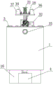
FIG. 1 is a three-dimensional schematic of the present invention;
FIG. 2 is a three-dimensional schematic of another perspective of the present invention;
FIG. 3 is a front view of the present invention;
FIG. 4 is a left side view of the present invention;
FIG. 5 is a right side view of the present invention;
FIG. 6 is a top view of the present invention;
FIG. 7 is a partial cross-sectional view of FIG. 3;
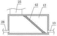
FIG. 8 is a cross-sectional view of a second separator tank of the present invention;
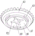
FIG. 9 is a three-dimensional schematic view of a first bevel gear of the present invention;
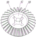
FIG. 10 is a three-dimensional schematic view of another perspective of the first bevel gear of the present invention;
FIG. 11 is a schematic connection diagram of a first circular tube, a rotary joint, a second circular tube, a rectangular plate and a third circular tube according to the present invention;
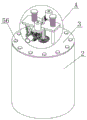
FIG. 12 is a schematic three-dimensional view of a second flocculation tank of the present invention;
FIG. 13 is a top view of FIG. 12;
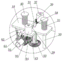
FIG. 14 is an enlarged view of portion A of the present invention;
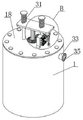
FIG. 15 is a three-dimensional schematic of a first flocculation tank of the present invention;
FIG. 16 is an enlarged view of portion B of the present invention;
fig. 17 is a schematic view showing the connection of the rotating plate, the rotating shaft and the vertical plate according to the present invention.
In the figure: 1. a first flocculation tank; 2. a second flocculation tank; 3. a top cover; 4. sludge treatment equipment; 5. a first discharge pipe; 6. a first separation tank; 7. a first infusion tube; 8. a first diaphragm pump; 9. a first electrically controlled valve; 10. a first liquid outlet pipe; 11. a second discharge pipe; 12. a second separation tank; 13. a second infusion tube; 14. a second diaphragm pump; 15. a third infusion tube; 16. a sedimentation tank; 17. a liquid discharge pipe; 18. moving the plate; 19. a second electrically controlled valve; 20. a first sludge pump; 21. a third electrically controlled valve; 22. a second sludge pump; 23. a first feed delivery pipe; 24. a first water pipe; 25. a second water pipe; 26. a first pneumatic gate valve; 27. a second starting gate valve; 28. a second delivery pipe; 29. a fourth electrically controlled valve; 30. a first guide bar; 31. a spring; 32. a motor; 33. a water inlet pipe; 34. a stirring blade; 35. a flange; 36. a polyaluminum chloride tank; 37. a polyacrylamide tank; 38. a first metering pump; 39. a second metering pump; 40. a limiting plate; 41. an L-shaped plate; 42. filtering with a screen; 43. a first bevel gear; 44. a second bevel gear; 45. an arc-shaped sliding block; 46. an annular guide rail; 47. a circular plate; 48. a circular hole; 49. a rectangular groove; 50. a first circular tube; 51. a rotary joint; 52. a second circular tube; 53. a rectangular plate; 54. a third circular tube; 55. a liquid outlet hole; 56. a bolt; 57. a first medicine inlet pipe; 58. a second medicine inlet pipe; 59. a first medicine outlet pipe; 60. a second medicine outlet pipe; 61. mounting a plate; 62. a rotating plate; 63. a vertical plate; 64. a vertical plate; 65. a rotating shaft; 66. a double-shaft speed reducer; 67. a second guide bar; 68. a ball; 69. a rectangular hole; 70. a circular baffle; 71. a rotating shaft; 72. a reinforcing plate; 73. a bearing; 74. a circular ring.
Detailed Description
The invention will be further described with reference to the accompanying drawings, without limiting the scope of the invention to the following:
the first embodiment is as follows: as shown in fig. 1-17, a multistage circulating sewage treatment device comprises a first flocculation tank 1, a second flocculation tank 2, a sludge treatment device 4 and a sedimentation tank 16, wherein a top cover 3 is fixedly mounted on the top of the first flocculation tank 1 and the top of the second flocculation tank 2, a first bevel gear 43 is rotatably connected to the top center of the top cover 3, a circular plate 47 is welded on the inner wall of the first bevel gear 43, a circular hole 48 is formed in the top center of the circular plate 47, a plurality of rectangular grooves 49 are formed in the inner wall of the circular hole 48 at equal intervals, a first guide rod 30 and a second guide rod 67 are fixedly mounted on the top of the top cover 3 respectively, a same movable plate 18 is slidably sleeved on the outer walls of the first guide rod 30 and the second guide rod 67, a limiting plate 40 is welded on the top of the first guide rod 30 and the outer wall of the second guide rod 67, a spring 31 is sleeved on the outer walls of the first guide rod 30 and the, the spring 31 is positioned between the limiting plate 40 and the moving plate 18, the bottom of the moving plate 18 is rotatably connected with a first circular tube 50, the top end of the first circular tube 50 penetrates through the moving plate 18 and is fixedly provided with a rotary joint 51, the bottom of the first circular tube 50 is fixedly provided with a second circular tube 52, the bottom of the second circular tube 52 penetrates through a circular hole 48 and is fixedly provided with a third circular tube 54, the outer wall of the third circular tube 54 is fixedly provided with a plurality of circular rings 74, the outer wall of each circular ring 74 is fixedly provided with a plurality of stirring blades 34, the outer wall of the third circular tube 54 is provided with a plurality of liquid outlet holes 55, the outer wall of the second circular tube 52 is fixedly provided with a plurality of rectangular plates 53, the rectangular plates 53 correspond to the rectangular grooves 49 one by one, and the rectangular plates 53 extend into the rectangular grooves 49 and;
a double-shaft speed reducer 66 is fixedly mounted on one side of the top cover 3, a motor 32 is fixedly mounted on one side of the double-shaft speed reducer 66, an output shaft of the motor 32 is fixedly connected with an input shaft of the double-shaft speed reducer 66, a second bevel gear 44 is fixedly mounted on one output shaft of the double-shaft speed reducer 66, the second bevel gear 44 is meshed with the first bevel gear 43, a lifting assembly for driving the moving plate 18 to lift is arranged on the top of the top cover 3, and a dosing assembly for adding polyaluminium chloride medicament and polyacrylamide medicament is arranged on the top of the moving plate 18;
a first water pipe 24 and a second water pipe 25 are respectively and fixedly installed at the bottom of the first flocculation tank 1 and the bottom of the second flocculation tank 2, a first pneumatic gate valve 26 and a second starting gate valve 27 are respectively and fixedly installed on the first water pipe 24 and the second water pipe 25, a first separation box 6 and a second separation box 12 are respectively and fixedly installed at the bottoms of the first water pipe 24 and the second water pipe 25, filter screens 42 are respectively and fixedly installed on the inner walls of the first separation box 6 and the second separation box 12, a first conveying pipe 23 and a first infusion pipe 7 are respectively and fixedly installed at the bottom parts of two sides of the first separation box 6, a first sludge pump 20 is fixedly installed at one end of the first conveying pipe 23, a first discharge pipe 5 is fixedly installed at a discharge port of the first sludge pump 20, one end of the first discharge pipe 5 is connected with a discharge pipe of a sludge treatment device 4, a second electric control valve 19 is fixedly installed on the first discharge pipe 5, a first diaphragm pump 8 is fixedly installed at one end of the first infusion pipe 7, a first liquid outlet pipe 10 is fixedly installed at a liquid outlet of the first diaphragm pump 8, one end of the first liquid outlet pipe 10 penetrates through the second flocculation tank 2 and extends into the second flocculation tank 2, a first electric control valve 9 is fixedly installed on the first liquid outlet pipe 10, a second material conveying pipe 28 and a second liquid conveying pipe 13 are respectively and fixedly installed at the bottom parts of two sides of the second separation tank 12, a second sludge pump 22 is fixedly installed at one end of the second material conveying pipe 28, a second material discharging pipe 11 is fixedly installed at a material outlet of the second sludge pump 22, one end of the second material discharging pipe 11 penetrates through the first flocculation tank 1 and extends into the first flocculation tank 1, a third electric control valve 21 is fixedly installed on the second material discharging pipe 11, a second diaphragm pump 14 is fixedly installed at one end of the second liquid conveying pipe 13, a third diaphragm pump 15 is fixedly installed at a liquid outlet of the second diaphragm pump 14, one end of the third liquid conveying pipe 15 penetrates through the sedimentation tank 16 and extends into the sedimentation, a fourth electric control valve 29 is fixedly arranged on the third infusion tube 15.
According to the invention, the lifting assembly comprises a vertical plate 64 fixedly mounted on the top of the top cover 3, one side of the vertical plate 64 is rotatably connected with a rotating plate 62, one side of the rotating plate 62 is provided with a rectangular hole 69, the inner wall of the rectangular hole 69 is slidably connected with a rotating shaft 71, one end of the rotating shaft 71 is rotatably connected with the vertical plate 63, one side of the vertical plate 63 is fixedly mounted with a rotating shaft 65, one end of the rotating shaft 65 is fixedly connected with the other output shaft of the double-shaft speed reducer 66, the outer wall of the rotating shaft 71 is fixedly sleeved with two circular baffles 70, and the two circular baffles 70.
According to the invention, the dosing assembly comprises a first metering pump 38 and a second metering pump 39 which are fixedly mounted on the top of a movable plate 18, mounting plates 61 are fixedly mounted on two sides of the movable plate 18 above a second flocculation tank 2, polymeric aluminum chloride tanks 36 and polyacrylamide tanks 37 are fixedly mounted on the tops of the two mounting plates 61 respectively, first drug inlet pipes 57 and second drug inlet pipes 58 are fixedly mounted on liquid inlets of the first metering pump 38 and the second metering pump 39 respectively, the first drug inlet pipes 57 and the second drug inlet pipes 58 extend into the polymeric aluminum chloride tanks 36 and the polyacrylamide tanks 37 respectively, first drug outlet pipes 59 and second drug outlet pipes 60 are fixedly mounted on liquid outlets of the first metering pump 38 and the second metering pump 39 respectively, and the first drug outlet pipes 59 and the second drug outlet pipes 60 are connected with a rotary joint 51.
In the invention, the top of the top cover 3 is fixedly provided with an L-shaped plate 41, the L-shaped plate 41 is positioned at one side of a double-shaft speed reducer 66, the bottom of a second guide rod 67 is fixedly connected with the top of the L-shaped plate 41, one side of the L-shaped plate 41 is fixedly provided with a reinforcing plate 72, and the bottom of the reinforcing plate 72 is fixedly connected with the top of the top cover 3.
In the invention, a plurality of bolts 56 are arranged on the top cover 3 at equal intervals, and the two top covers 3 are respectively fixedly connected with the first flocculation tank 1 and the second flocculation tank 2 through the bolts 56.
In the invention, a water inlet pipe 33 is fixedly arranged at the top of one side of the first flocculation tank 1, and a flange 35 is fixedly arranged at one side of the water inlet pipe 33.
In the invention, a drain pipe 17 is fixedly arranged at the bottom of one side of the sedimentation tank 16.
In the invention, a bearing 73 is fixedly embedded on the moving plate 18, and the inner ring of the bearing 73 is fixedly connected with the outer wall of the first circular tube 50.
In the invention, the top of the top cover 3 is fixedly provided with an annular guide rail 46, the bottom of the circular plate 47 is fixedly provided with a plurality of arc-shaped sliding blocks 45 which are arranged at equal intervals, and the arc-shaped sliding blocks 45 are connected with the annular guide rail 46 in a sliding way.
In the present invention, a spherical ball 68 is fixedly mounted on the top of the rotating plate 62, and the outer wall of the spherical ball 68 contacts the bottom of the moving plate 18.
The working principle is as follows: the sewage pipe of the water inlet pipe 33 is connected through the water inlet pipe 33, the sewage can enter the first flocculation tank 1 through the water inlet pipe 33, at the moment, the first pneumatic gate valve 26 is opened, the sewage in the first flocculation tank 1 can enter the first separation box 6 through the first water pipe 24, the first diaphragm pump 8 and the first electric control valve 9 are started, the first diaphragm pump 8 can convey the sewage into the second flocculation tank 2 through the first infusion pipe 7 and the first liquid outlet pipe 10, at the moment, the sewage can enter the second flocculation tank 2 after being filtered by the filter screen 42 in the first separation box 6, after the sewage in the first flocculation tank 1 is conveyed into the second flocculation tank 2, the first pneumatic gate valve 26, the first diaphragm pump 8 and the first electric control valve 9 are closed, the motor 32 above the second flocculation tank 2 is started, the motor 32 can respectively drive the second bevel gear 44 and the rotating shaft 65 to rotate through the double-shaft speed reducer 66, the second bevel gear 44 can drive the first bevel gear 43 to rotate, the first bevel gear 43 can drive the arc-shaped sliding block 45 to slide on the annular guide rail 46, the first bevel gear 43 can drive the circular plate 47, the rectangular plate 53, the second circular tube 52, the third circular tube 54 and the stirring blade 34 to rotate, the stirring blade 34 can stir the sewage, the rotating shaft 65 can drive the vertical plate 63 and the rotating shaft 71 to do circular motion around the rotating shaft 65, the rotating shaft 71 can slide in the rectangular hole 69 in the circular motion process of the rotating shaft 71 and drive the rotating plate 62 to swing around the vertical plate 64 as a pivot, in the swing process of the vertical plate 64, the vertical plate 64 can drive the round ball 68 to slide at the bottom of the moving plate 18 and push the moving plate 18 to slide on the first guide rod 30 and the second guide rod 67, and in the swing process of the round ball 68 from the lowest point to the highest point, the movable plate 18 is pushed to move upwards, the spring 31 is compressed, in the process that the ball 68 swings from the highest point to the lowest point, the movable plate 18 can move downwards due to the elastic force of the spring 31, the movable plate 18 can move longitudinally in a reciprocating manner, the movable plate 18 can drive the second circular tube 52, the third circular tube 54 and the stirring blade 34 to move longitudinally in a reciprocating manner, the rectangular plate 53 can slide longitudinally in the rectangular groove 49, the first metering pump 38 is started, the first metering pump 38 can convey polyaluminium chloride solution to the rotary joint 51 through the first medicine inlet tube 57 and the first medicine outlet tube 59, the polyaluminium chloride solution can sequentially pass through the first circular tube 50, the second circular tube 52 and the third circular tube 54 and is finally sprayed out through the plurality of liquid outlet holes 55, after the required dosage is added, the first metering pump 38 is closed, the third circular tube 54 can rotate while adding the polyaluminium chloride solution to the sewage, namely, when the mixture is stirred, the liquid medicine is added, the time can be greatly saved, after the polyaluminium chloride solution is uniformly mixed with the sewage, the second metering pump 39 is started, the second metering pump 39 can add the polyacrylamide solution into the second flocculation tank 2 through the second medicine inlet pipe 58 and the second medicine outlet pipe 60, similarly, the third circular pipe 54 can rotate while adding the polyacrylamide solution into the sewage, after the mixture is uniformly mixed, the second starting gate valve 27 is started, the sewage and the sludge in the second flocculation tank 2 flow into the second separation tank 12 together, the second diaphragm pump 14 and the fourth electric control valve 29 are started, the second diaphragm pump 14 can convey the water filtered by the filter screen 42 into the sedimentation tank 16 through the second liquid conveying pipe 13 and the third liquid conveying pipe 15 for standing, the sludge and the effective mixed flocculant can be blocked by the filter screen 42 on one side of the filter screen 42, after the water in the second flocculation tank 2 is conveyed into the sedimentation tank 16, closing the second diaphragm pump 14 and the fourth electric control valve 29, and opening the second sludge pump 22 and the third electric control valve 21, the second sludge pump 22 can convey sludge and effective mixed flocculant into the first flocculation tank 1 through the second material conveying pipe 28 and the second material discharging pipe 11, starting the motor 32 above the first flocculation tank 1, the motor 32 can drive the stirring blade 34 in the first flocculation tank 1 to longitudinally reciprocate and rotate, the effective mixed flocculant can flocculate the sewage in the first flocculation tank 1, after the treatment is completed, opening the first pneumatic gate valve 26 and conveying the pretreated sewage to the second flocculation tank 2 through the first material conveying pipe 8 for secondary treatment, and additionally opening the first sludge pump 20 and the second electric control valve 19, the first sludge pump 20 can convey the sludge into the sludge treatment equipment 4 through the first material conveying pipe 23 and the first material discharging pipe 5, the sewage treatment efficiency can be improved, the stirring time can be reduced, the flocculation effect is improved, the flocculating agent is fully utilized, and the use is convenient.
However, as is well known to those skilled in the art, the working principle and wiring method of the electrically controlled valve, the motor 32 and the rotary joint 51 are conventional in the art and will not be described herein, and those skilled in the art can make any choice according to their needs or convenience.
The foregoing is illustrative of the preferred embodiments of this invention, and it is to be understood that the invention is not limited to the precise form disclosed herein and that various other combinations, modifications, and environments may be resorted to, falling within the scope of the concept as disclosed herein, either as described above or as apparent to those skilled in the relevant art. And that modifications and variations may be effected by those skilled in the art without departing from the spirit and scope of the invention as defined by the appended claims.
Claims (10)
1. The utility model provides a multistage circulating sewage treatment plant, includes first flocculation tank (1), second flocculation tank (2), sludge treatment equipment (4) and sedimentation tank (16), its characterized in that: the top of first flocculation tank (1) and the equal fixed mounting in top of second flocculation tank (2) have top cap (3), the top central point of top cap (3) puts and all rotates and is connected with first bevel gear (43), the inner wall welding of first bevel gear (43) has plectane (47), the top central point of plectane (47) puts and is provided with round hole (48), the inner wall of round hole (48) is provided with rectangular channel (49) that a plurality of equidistant settings, the top of top cap (3) is fixed mounting respectively has first guide arm (30) and second guide arm (67), it is equipped with same movable plate (18) to slide the cover on the outer wall of first guide arm (30) and second guide arm (67), limiting plate (40) have all been welded at the top of first guide arm (30) and second guide arm (67), all the cover is equipped with spring (31) on the outer wall of first guide arm (30) and second guide arm (67), the spring (31) is located between the limiting plate (40) and the moving plate (18), the bottom of the moving plate (18) is rotatably connected with a first round pipe (50), the top end of the first round pipe (50) runs through the moving plate (18) and is fixedly provided with a rotary joint (51), the bottom of the first round pipe (50) is fixedly provided with a second round pipe (52), the bottom of the second round pipe (52) runs through a round hole (48) and is fixedly provided with a third round pipe (54), the outer wall of the third round pipe (54) is fixedly provided with a plurality of rings (74), the outer wall of the rings (74) is fixedly provided with a plurality of stirring blades (34), the outer wall of the third round pipe (54) is provided with a plurality of liquid outlet holes (55), the outer wall of the second round pipe (52) is fixedly provided with a plurality of rectangular plates (53), the rectangular plates (53) are in one-to-one correspondence with the rectangular grooves (49), the rectangular plate (53) extends into the rectangular groove (49) and is connected with the rectangular groove (49) in a sliding mode;
a double-shaft speed reducer (66) is fixedly mounted on one side of the top cover (3), a motor (32) is fixedly mounted on one side of the double-shaft speed reducer (66), an output shaft of the motor (32) is fixedly connected with an input shaft of the double-shaft speed reducer (66), a second bevel gear (44) is fixedly mounted on one output shaft of the double-shaft speed reducer (66), the second bevel gear (44) is meshed with the first bevel gear (43), a lifting assembly used for driving the moving plate (18) to lift is arranged on the top of the top cover (3), and a dosing assembly used for adding polyaluminium chloride and polyacrylamide medicaments is arranged on the top of the moving plate (18);
the bottom of the first flocculation tank (1) and the bottom of the second flocculation tank (2) are respectively and fixedly provided with a first water pipe (24) and a second water pipe (25), the first water pipe (24) and the second water pipe (25) are respectively and fixedly provided with a first pneumatic gate valve (26) and a second starting gate valve (27), the bottoms of the first water pipe (24) and the second water pipe (25) are respectively and fixedly provided with a first separation box (6) and a second separation box (12), the inner walls of the first separation box (6) and the second separation box (12) are respectively and fixedly provided with a filter screen (42), the two side bottoms of the first separation box (6) are respectively and fixedly provided with a first conveying pipeline (23) and a first sludge pump (7), one end of the first conveying pipeline (23) is fixedly provided with a first sludge pump (20), and a discharge pipe (5) is fixedly provided at the discharge port of the first sludge pump (20), the one end of first discharging pipe (5) is connected with sludge treatment equipment (4), fixed mounting has second automatically controlled valve (19) on first discharging pipe (5), the one end fixed mounting of first transfer line (7) has first diaphragm pump (8), the liquid outlet fixed mounting of first diaphragm pump (8) has first drain pipe (10), the one end of first drain pipe (10) runs through second flocculation jar (2) and extends in second flocculation jar (2), fixed mounting has first automatically controlled valve (9) on first drain pipe (10), the both sides bottom of second separator box (12) is fixed mounting respectively has second transfer line (28) and second transfer line (13), the one end fixed mounting of second transfer line (28) has second sludge pump (22), the discharge gate fixed mounting of second sludge pump (22) has second discharging pipe (11), the one end of second discharging pipe (11) runs through first flocculation tank (1) and extends in first flocculation tank (1), fixed mounting has third automatically controlled valve (21) on second discharging pipe (11), the one end fixed mounting of second transfer line (13) has second diaphragm pump (14), the liquid outlet fixed mounting of second diaphragm pump (14) has third transfer line (15), the one end of third transfer line (15) is run through sedimentation tank (16) and is extended in sedimentation tank (16), fixed mounting has fourth automatically controlled valve (29) on third transfer line (15).
2. The sewage treatment plant of claim 1, wherein: lifting unit includes top cap (3) top fixed mounting's riser (64), one side of riser (64) is rotated and is connected with rotor plate (62), one side of rotor plate (62) is provided with rectangular hole (69), the inner wall sliding connection of rectangular hole (69) has rotation axis (71), the one end of rotation axis (71) is rotated and is connected with riser (63), one side fixed mounting of riser (63) has pivot (65), another output shaft fixed connection of the one end of pivot (65) and biax speed reducer (66), the fixed cover is equipped with two circular baffle (70) on the outer wall of rotation axis (71), two circular baffle (70) are located the both sides of rotor plate (62) respectively.
3. The sewage treatment plant of claim 1, wherein: the dosing assembly comprises a first metering pump (38) and a second metering pump (39) which are fixedly installed at the top of the moving plate (18), mounting plates (61) are fixedly installed on two sides of the moving plate (18) above the second flocculation tank (2), a polyaluminium chloride tank (36) and a polyacrylamide tank (37) are respectively and fixedly installed at the tops of the two mounting plates (61), the liquid inlets of the first metering pump (38) and the second metering pump (39) are respectively and fixedly provided with a first medicine inlet pipe (57) and a second medicine inlet pipe (58), the first medicine inlet pipe (57) and the second medicine inlet pipe (58) respectively extend into the polyaluminium chloride tank (36) and the polyacrylamide tank (37), the liquid outlets of the first metering pump (38) and the second metering pump (39) are respectively and fixedly provided with a first medicine outlet pipe (59) and a second medicine outlet pipe (60), the first medicine outlet pipe (59) and the second medicine outlet pipe (60) are connected with the rotary joint (51).
4. The sewage treatment plant of claim 1, wherein: the top fixed mounting of top cap (3) has L template (41), L template (41) are located one side of double-shaft speed reducer (66), the bottom of second guide arm (67) and the top fixed connection of L template (41), one side fixed mounting of L template (41) has reinforcing plate (72), the bottom of reinforcing plate (72) and the top fixed connection of top cap (3).
5. The sewage treatment plant of claim 1, wherein: be provided with bolt (56) that a plurality of equidistant settings on top cap (3), two top caps (3) all through bolt (56) respectively with first flocculation tank (1) and second flocculation tank (2) fixed connection.
6. The sewage treatment plant of claim 1, wherein: one side top fixed mounting of first flocculation tank (1) has inlet tube (33), one side fixed mounting of inlet tube (33) has flange (35).
7. The sewage treatment plant of claim 1, wherein: and a liquid discharge pipe (17) is fixedly arranged at the bottom of one side of the sedimentation tank (16).
8. The sewage treatment plant of claim 1, wherein: a bearing (73) is fixedly embedded in the moving plate (18), and an inner ring of the bearing (73) is fixedly connected with the outer wall of the first circular tube (50).
9. The sewage treatment plant of claim 1, wherein: the top fixed mounting of top cap (3) has annular guide rail (46), the bottom fixed mounting of plectane (47) has arc slider (45) of a plurality of equidistant settings, arc slider (45) and annular guide rail (46) sliding connection.
10. The sewage treatment plant of claim 2, wherein: the top of the rotating plate (62) is fixedly provided with a round ball (68), and the outer wall of the round ball (68) is contacted with the bottom of the moving plate (18).
Priority Applications (1)
| Application Number | Priority Date | Filing Date | Title |
|---|---|---|---|
| CN202110060916.6A CN112607922A (en) | 2021-01-18 | 2021-01-18 | Multistage circulating sewage treatment plant |
Applications Claiming Priority (1)
| Application Number | Priority Date | Filing Date | Title |
|---|---|---|---|
| CN202110060916.6A CN112607922A (en) | 2021-01-18 | 2021-01-18 | Multistage circulating sewage treatment plant |
Publications (1)
| Publication Number | Publication Date |
|---|---|
| CN112607922A true CN112607922A (en) | 2021-04-06 |
Family
ID=75254129
Family Applications (1)
| Application Number | Title | Priority Date | Filing Date |
|---|---|---|---|
| CN202110060916.6A Pending CN112607922A (en) | 2021-01-18 | 2021-01-18 | Multistage circulating sewage treatment plant |
Country Status (1)
| Country | Link |
|---|---|
| CN (1) | CN112607922A (en) |
Cited By (3)
| Publication number | Priority date | Publication date | Assignee | Title |
|---|---|---|---|---|
| CN115572041A (en) * | 2022-10-26 | 2023-01-06 | 上海昂莱机电东台有限公司 | Flocculating agent charge device for sludge treatment |
| CN115594266A (en) * | 2022-09-01 | 2023-01-13 | 安徽舒饰环保科技有限公司(Cn) | Processing system of electroplating metal sewage |
| CN119774734A (en) * | 2025-02-27 | 2025-04-08 | 苏州冠礼科技有限公司 | A chemical cleaning liquid treatment circulation device for semiconductor polishing process |
Citations (5)
| Publication number | Priority date | Publication date | Assignee | Title |
|---|---|---|---|---|
| JPS62197111A (en) * | 1986-02-25 | 1987-08-31 | Kurita Water Ind Ltd | Flocculative reaction tank |
| US20100051526A1 (en) * | 2005-07-06 | 2010-03-04 | Siemens Water Technologies | Phosphorous removal system and process |
| CN208327490U (en) * | 2018-04-17 | 2019-01-04 | 云南嘉科环保设备有限公司 | Flocculant dosing blender |
| CN110681279A (en) * | 2019-11-08 | 2020-01-14 | 四川轻化工大学 | A yak milk cheese production device |
| CN211367257U (en) * | 2019-12-28 | 2020-08-28 | 浙江瑞启检测技术有限公司 | An industrial waste water treatment device |
-
2021
- 2021-01-18 CN CN202110060916.6A patent/CN112607922A/en active Pending
Patent Citations (5)
| Publication number | Priority date | Publication date | Assignee | Title |
|---|---|---|---|---|
| JPS62197111A (en) * | 1986-02-25 | 1987-08-31 | Kurita Water Ind Ltd | Flocculative reaction tank |
| US20100051526A1 (en) * | 2005-07-06 | 2010-03-04 | Siemens Water Technologies | Phosphorous removal system and process |
| CN208327490U (en) * | 2018-04-17 | 2019-01-04 | 云南嘉科环保设备有限公司 | Flocculant dosing blender |
| CN110681279A (en) * | 2019-11-08 | 2020-01-14 | 四川轻化工大学 | A yak milk cheese production device |
| CN211367257U (en) * | 2019-12-28 | 2020-08-28 | 浙江瑞启检测技术有限公司 | An industrial waste water treatment device |
Non-Patent Citations (1)
| Title |
|---|
| 张建丰: "《活性污泥法工艺控制》", 31 January 2007, 中国电力出版社 * |
Cited By (5)
| Publication number | Priority date | Publication date | Assignee | Title |
|---|---|---|---|---|
| CN115594266A (en) * | 2022-09-01 | 2023-01-13 | 安徽舒饰环保科技有限公司(Cn) | Processing system of electroplating metal sewage |
| CN115594266B (en) * | 2022-09-01 | 2024-04-30 | 安徽舒饰环保科技有限公司 | Electroplating metal sewage treatment system |
| CN115572041A (en) * | 2022-10-26 | 2023-01-06 | 上海昂莱机电东台有限公司 | Flocculating agent charge device for sludge treatment |
| CN115572041B (en) * | 2022-10-26 | 2023-12-26 | 上海昂莱机电东台有限公司 | Flocculant dosing device for sludge treatment |
| CN119774734A (en) * | 2025-02-27 | 2025-04-08 | 苏州冠礼科技有限公司 | A chemical cleaning liquid treatment circulation device for semiconductor polishing process |
Similar Documents
| Publication | Publication Date | Title |
|---|---|---|
| CN107381874A (en) | A kind of tin metallurgy desulfurization wastewater neutralizing device | |
| CN110902791A (en) | Energy-saving sewage treatment device and treatment method | |
| CN210457754U (en) | A kind of domestic sewage environmental protection treatment equipment | |
| CN211999184U (en) | Integrated sewage treatment device | |
| CN214270240U (en) | Sewage mixing treatment device | |
| CN116589063B (en) | Groundwater pollution filtration purifier | |
| CN212356937U (en) | A high-efficiency biological treatment device for electroplating wastewater | |
| CN216934832U (en) | Flocculent impurity sedimentation tank of sewage | |
| CN112661302B (en) | Power plant wastewater treatment recycling device and recycling method thereof | |
| CN216662708U (en) | Energy-saving efficient water pollution treatment device for aluminum profile production | |
| CN216639119U (en) | River water purifying equipment | |
| CN112723498B (en) | Nanocrystalline magnetic coagulation equipment for heavy metal wastewater treatment | |
| CN214990733U (en) | Domestic waste incineration fly ash washing liquid pretreatment system | |
| CN214218376U (en) | Sewage flocculation device | |
| CN213141794U (en) | Sludge conditioning tank | |
| CN209974327U (en) | Stirring formula sewage treatment plant | |
| CN221191938U (en) | Domestic sewage water quality treatment device | |
| CN223906684U (en) | Industrial wastewater's resourceful treatment device | |
| CN116495859B (en) | Dynamic and static switching dosing type chemical sewage filtering equipment | |
| CN216141370U (en) | Sewage treatment mixes storehouse | |
| CN112723627A (en) | Water plant sewage rapid filtration sterilization device | |
| CN216336658U (en) | Quick purification treatment system of waste water | |
| CN215946850U (en) | Sewage treatment sedimentation tank | |
| CN223372936U (en) | Innocent treatment device for graphite processing acid wastewater | |
| CN223620210U (en) | Novel environmental protection sewage treatment device |
Legal Events
| Date | Code | Title | Description |
|---|---|---|---|
| PB01 | Publication | ||
| PB01 | Publication | ||
| SE01 | Entry into force of request for substantive examination | ||
| SE01 | Entry into force of request for substantive examination | ||
| RJ01 | Rejection of invention patent application after publication |
Application publication date: 20210406 |
|
| RJ01 | Rejection of invention patent application after publication |