CN112606194B - Concrete pile production facility - Google Patents
Concrete pile production facility Download PDFInfo
- Publication number
- CN112606194B CN112606194B CN202011626233.4A CN202011626233A CN112606194B CN 112606194 B CN112606194 B CN 112606194B CN 202011626233 A CN202011626233 A CN 202011626233A CN 112606194 B CN112606194 B CN 112606194B
- Authority
- CN
- China
- Prior art keywords
- gear
- main body
- motor
- rotating shaft
- fixed
- Prior art date
- Legal status (The legal status is an assumption and is not a legal conclusion. Google has not performed a legal analysis and makes no representation as to the accuracy of the status listed.)
- Active
Links
- 239000004567 concrete Substances 0.000 title claims abstract description 47
- 238000004519 manufacturing process Methods 0.000 title claims abstract description 17
- 239000000463 material Substances 0.000 claims abstract description 95
- 230000007306 turnover Effects 0.000 claims abstract description 20
- 238000003756 stirring Methods 0.000 claims description 32
- 239000002699 waste material Substances 0.000 abstract description 5
- 238000005056 compaction Methods 0.000 abstract description 3
- 238000012856 packing Methods 0.000 abstract 1
- 238000007493 shaping process Methods 0.000 abstract 1
- 208000037805 labour Diseases 0.000 description 5
- 230000000694 effects Effects 0.000 description 3
- 238000002360 preparation method Methods 0.000 description 2
- 239000002994 raw material Substances 0.000 description 2
- 229910000831 Steel Inorganic materials 0.000 description 1
- 230000009286 beneficial effect Effects 0.000 description 1
- 239000002131 composite material Substances 0.000 description 1
- 238000010276 construction Methods 0.000 description 1
- 239000011513 prestressed concrete Substances 0.000 description 1
- 239000011150 reinforced concrete Substances 0.000 description 1
- 239000010959 steel Substances 0.000 description 1
- 230000001360 synchronised effect Effects 0.000 description 1
- 239000002023 wood Substances 0.000 description 1
Images



Classifications
-
- B—PERFORMING OPERATIONS; TRANSPORTING
- B28—WORKING CEMENT, CLAY, OR STONE
- B28B—SHAPING CLAY OR OTHER CERAMIC COMPOSITIONS; SHAPING SLAG; SHAPING MIXTURES CONTAINING CEMENTITIOUS MATERIAL, e.g. PLASTER
- B28B15/00—General arrangement or layout of plant ; Industrial outlines or plant installations
-
- B—PERFORMING OPERATIONS; TRANSPORTING
- B28—WORKING CEMENT, CLAY, OR STONE
- B28B—SHAPING CLAY OR OTHER CERAMIC COMPOSITIONS; SHAPING SLAG; SHAPING MIXTURES CONTAINING CEMENTITIOUS MATERIAL, e.g. PLASTER
- B28B1/00—Producing shaped prefabricated articles from the material
- B28B1/04—Producing shaped prefabricated articles from the material by tamping or ramming
- B28B1/045—Producing shaped prefabricated articles from the material by tamping or ramming combined with vibrating or jolting
-
- B—PERFORMING OPERATIONS; TRANSPORTING
- B28—WORKING CEMENT, CLAY, OR STONE
- B28B—SHAPING CLAY OR OTHER CERAMIC COMPOSITIONS; SHAPING SLAG; SHAPING MIXTURES CONTAINING CEMENTITIOUS MATERIAL, e.g. PLASTER
- B28B13/00—Feeding the unshaped material to moulds or apparatus for producing shaped articles; Discharging shaped articles from such moulds or apparatus
- B28B13/02—Feeding the unshaped material to moulds or apparatus for producing shaped articles
- B28B13/0215—Feeding the moulding material in measured quantities from a container or silo
- B28B13/026—Feeding the moulding material in measured quantities from a container or silo by using a movable hopper transferring the moulding material to the moulding cavities
-
- B—PERFORMING OPERATIONS; TRANSPORTING
- B28—WORKING CEMENT, CLAY, OR STONE
- B28B—SHAPING CLAY OR OTHER CERAMIC COMPOSITIONS; SHAPING SLAG; SHAPING MIXTURES CONTAINING CEMENTITIOUS MATERIAL, e.g. PLASTER
- B28B13/00—Feeding the unshaped material to moulds or apparatus for producing shaped articles; Discharging shaped articles from such moulds or apparatus
- B28B13/04—Discharging the shaped articles
- B28B13/06—Removing the shaped articles from moulds
- B28B13/065—Removing the shaped articles from moulds by applying electric current or other means of discharging, e.g. pneumatic or hydraulic discharging means
-
- B—PERFORMING OPERATIONS; TRANSPORTING
- B28—WORKING CEMENT, CLAY, OR STONE
- B28B—SHAPING CLAY OR OTHER CERAMIC COMPOSITIONS; SHAPING SLAG; SHAPING MIXTURES CONTAINING CEMENTITIOUS MATERIAL, e.g. PLASTER
- B28B17/00—Details of, or accessories for, apparatus for shaping the material; Auxiliary measures taken in connection with such shaping
-
- B—PERFORMING OPERATIONS; TRANSPORTING
- B28—WORKING CEMENT, CLAY, OR STONE
- B28C—PREPARING CLAY; PRODUCING MIXTURES CONTAINING CLAY OR CEMENTITIOUS MATERIAL, e.g. PLASTER
- B28C5/00—Apparatus or methods for producing mixtures of cement with other substances, e.g. slurries, mortars, porous or fibrous compositions
- B28C5/08—Apparatus or methods for producing mixtures of cement with other substances, e.g. slurries, mortars, porous or fibrous compositions using driven mechanical means affecting the mixing
- B28C5/10—Mixing in containers not actuated to effect the mixing
- B28C5/12—Mixing in containers not actuated to effect the mixing with stirrers sweeping through the materials, e.g. with incorporated feeding or discharging means or with oscillating stirrers
- B28C5/14—Mixing in containers not actuated to effect the mixing with stirrers sweeping through the materials, e.g. with incorporated feeding or discharging means or with oscillating stirrers the stirrers having motion about a horizontal or substantially horizontal axis
-
- B—PERFORMING OPERATIONS; TRANSPORTING
- B28—WORKING CEMENT, CLAY, OR STONE
- B28C—PREPARING CLAY; PRODUCING MIXTURES CONTAINING CLAY OR CEMENTITIOUS MATERIAL, e.g. PLASTER
- B28C7/00—Controlling the operation of apparatus for producing mixtures of clay or cement with other substances; Supplying or proportioning the ingredients for mixing clay or cement with other substances; Discharging the mixture
- B28C7/16—Discharge means, e.g. with intermediate storage of fresh concrete
-
- E—FIXED CONSTRUCTIONS
- E02—HYDRAULIC ENGINEERING; FOUNDATIONS; SOIL SHIFTING
- E02D—FOUNDATIONS; EXCAVATIONS; EMBANKMENTS; UNDERGROUND OR UNDERWATER STRUCTURES
- E02D5/00—Bulkheads, piles, or other structural elements specially adapted to foundation engineering
- E02D5/22—Piles
- E02D5/24—Prefabricated piles
- E02D5/30—Prefabricated piles made of concrete or reinforced concrete or made of steel and concrete
-
- E—FIXED CONSTRUCTIONS
- E02—HYDRAULIC ENGINEERING; FOUNDATIONS; SOIL SHIFTING
- E02D—FOUNDATIONS; EXCAVATIONS; EMBANKMENTS; UNDERGROUND OR UNDERWATER STRUCTURES
- E02D2300/00—Materials
- E02D2300/0004—Synthetics
- E02D2300/0018—Cement used as binder
- E02D2300/002—Concrete
Landscapes
- Engineering & Computer Science (AREA)
- Mechanical Engineering (AREA)
- Chemical & Material Sciences (AREA)
- Ceramic Engineering (AREA)
- Structural Engineering (AREA)
- Manufacturing & Machinery (AREA)
- Dispersion Chemistry (AREA)
- Life Sciences & Earth Sciences (AREA)
- General Life Sciences & Earth Sciences (AREA)
- Mining & Mineral Resources (AREA)
- Paleontology (AREA)
- Civil Engineering (AREA)
- General Engineering & Computer Science (AREA)
- Devices For Post-Treatments, Processing, Supply, Discharge, And Other Processes (AREA)
Abstract
The invention relates to the field of concrete pile production equipment, in particular to concrete pile production equipment which comprises a main body, a moving mechanism, a quantifying mechanism, a material transferring mechanism, a turnover mechanism and a vibration mechanism, wherein the main body is provided with a plurality of positioning holes; the proper amount of material can be toward the inside release of passing material mechanism through the setting of dosing mechanism, avoid releasing the waste that too much caused, the result of use of equipment has been improved, can pass the material inside tilting mechanism's mould part through the setting of passing material mechanism, and can initiatively retrieve remaining material, the trafficability characteristic of remaining material influence spare part has been avoided, can vibrate the compaction to the material of the inside packing of tilting mechanism through the setting of vibration mechanism, improve the quality and the shaping efficiency of product, can back-off the position of convenient transport with the concrete pile of having made through tilting mechanism's setting, manpower participation upset has been avoided, the labour has been saved, can move out the space of convenient transport product after the product drawing of patterns through the setting of moving mechanism.
Description
Technical Field
The invention relates to the field of concrete pile production equipment, in particular to concrete pile production equipment.
Background
Concrete piles are piles made of concrete (including ordinary reinforced concrete, prestressed concrete). The composite material has the advantages of wood and steel saving, durability, low manufacturing cost and the like, is widely used in foundation engineering of hydraulic buildings, industrial buildings, civil buildings and bridges, and is also commonly used for anti-sliding or water-resisting of side slopes and foundation pit supporting.
Concrete pile generally is used for playing the guard action on the road, and along with road construction's is vigorous and admirable, concrete pile demand is also serious day by day to need a production facility that the preparation is efficient, however traditional concrete pile preparation mostly adopts the manual work to deliver the material inside the mould, uses vibrations instrument to compact it afterwards, and the mould that overturns at last breaks away from the finished product mould, and this kind of manual work mode has consumed a large amount of labours, thereby the cost is increased, the product competitiveness that has reduced.
Disclosure of Invention
Aiming at the problems in the prior art, the invention provides concrete pile production equipment.
The technical scheme adopted by the invention for solving the technical problems is as follows: the utility model provides a concrete pile production facility, includes main part, moving mechanism, dosing mechanism, passes material mechanism, tilting mechanism and vibration mechanism, is used for the ration release concrete dosing mechanism locates the inside of main part is used for filling the concrete inside the tilting mechanism mould part pass material mechanism and locate the inside of main part, be used for with the concrete compaction after filling vibration mechanism locates pass the inside of material mechanism, be used for with the concrete pile back-off drawing of patterns that makes the tilting mechanism locates the inside of main part is used for vacating the removal space for the finished product moving mechanism locates the inside of main part.
Specifically, the quantitative mechanism comprises a material storage box, a stirring cavity, a third rotating shaft, a stirring wheel, a quantitative groove, a second motor, a belt pulley and a connecting belt, the material storage box is arranged in the main body, the stirring cavity is arranged in the material storage box, the stirring cavity and the inner part of the bottom end of the material storage box are respectively provided with a third rotating shaft in a rotating way, the third rotating shaft is rotatably connected with the material storage box, one side of the material storage box is provided with the second motor, the end parts of the second motor and the third rotating shaft are respectively fixed with one belt pulley, the connecting belts are wound among the plurality of belt pulleys, the side wall of the third rotating shaft positioned in the stirring cavity is fixed with the stirring wheel, the side wall of the other third rotating shaft is fixed with the quantitative wheel, and a plurality of quantitative grooves are formed in the quantitative wheel.
Concretely, it includes telescopic cylinder, movable box, baffle and receipts surplus groove to pass material mechanism, the bottom of storage case is equipped with telescopic cylinder, telescopic cylinder's one end is fixed with the movable box, the bottom of movable box slide in the inside of main part, one side of movable box is equipped with receive surplus groove and inside rotation and have the baffle.
Specifically, vibration mechanism includes vibration board, slide bar, connecting rod, carousel and third motor, the lateral wall internally mounted of removal case has the third motor, the one end of third motor is equipped with two the carousel, two the carousel rotate respectively in the inside of removal case and between the two rotate connect in the connecting rod, the one end of third motor is fixed in one of them the tip of carousel, the bottom of connecting rod is rotated and is connected with the slide bar, vibration board pass through slide bar sliding connection in remove the case.
Specifically, the turnover mechanism comprises a die body, a slide block, a wire column, a third gear, a rack, a fourth gear, a fifth gear and a fourth motor, the main body is internally provided with the die body, two ends of the die body are respectively provided with the slide block, the sliding block slides in the main body, the middle part of the sliding block is in threaded connection with the screw post, two ends of the screw post extend to the outer part of the sliding block, and the end part of the screw post rotates in the main body, the third gear is rotated in the slide block, one end of the third gear is fixed on the die body, one side of the third gear is meshed with the rack, the rack is fixed on the inner wall of the main body, the top end of the screw column is fixed with the fourth gear, one side of the fourth gear is engaged with the fifth gear, the top end of the fifth gear is fixed with the fourth motor, and the fourth motor is installed inside the main body.
Specifically, moving mechanism includes first motor, first pivot, first gear, second pivot, second gear, gyro wheel and guide rail, install on the top of main part first motor, the both ends of first motor are fixed with one respectively first pivot, the bottom of main part is equipped with two the guide rail, the top roll of guide rail has two the gyro wheel, one of them the tip of gyro wheel and the tip of first pivot is fixed with one respectively first gear, two one side of first gear is engaged with one respectively perpendicularly the second gear, two be fixed with between the second gear the second pivot, the second pivot rotate in inside the main part lateral wall.
The invention has the beneficial effects that:
(1) the invention relates to concrete pile production equipment, wherein a quantifying mechanism is arranged in a main body, a proper amount of materials can be released into a material delivering mechanism through the arrangement of the quantifying mechanism, the waste caused by excessive release is avoided, the use effect of the equipment is improved, the material delivering mechanism is arranged in the main body, the materials can be delivered into a mould part of a turnover mechanism through the arrangement of the material delivering mechanism, the residual materials can be actively recycled, and the influence of the residual materials on the trafficability of parts is avoided, namely, when the internal materials of a storage box need to be released, a second motor is started firstly, the second motor causes two third rotating shafts to synchronously rotate through a belt pulley and a connecting belt, one third rotating shaft drives a stirring wheel to stir the materials in a stirring cavity, and the other third rotating shaft realizes quantitative release of the materials by utilizing a quantifying groove in the quantifying wheel, set up through the stirring wheel can delay the concrete caking, and then can be toward passing the inside release proper amount material of material mechanism, avoid releasing the waste that too much caused, the result of use of equipment has been improved, because the storage case is when releasing the material, the flexible hydro-cylinder of operation will remove the bottom that the case slided the storage case before this, reuse flexible hydro-cylinder fills the inside of mould body with the material after holding proper amount material, it is when returning back to remove the case, the baffle can be contradicted by the material of leaving over and deflect, make the material enter into the inside of removing the case, when later removing the case and removing the raw materials, the material of leaving over before the bottom of baffle can be shoveled, and then can deliver inside tilting mechanism's the mould part with the material, and can initiatively retrieve remaining material, the trafficability that remaining material influences spare part has been avoided.
(2) According to the concrete pile production equipment, the vibrating mechanism is arranged inside the material delivery mechanism, the materials filled inside the overturning mechanism can be vibrated and compacted through the arrangement of the vibrating mechanism, the quality and the forming efficiency of products are improved, the overturning mechanism is arranged inside the main body, the manufactured concrete pile can be turned upside down to a position convenient to carry through the arrangement of the overturning mechanism, the manual overturning is avoided, the labor force is saved, namely, after the moving box is filled in the mould body, the moving box is positioned at the top end of the mould body at the moment, the third motor is started, the third motor drives the two turntables to rotate, the connecting rod rotates in an offset mode on the two turntables, the bottom end of the vibrating plate can be filled with the concrete in a reciprocating mode when the turntables rotate, the materials filled inside the overturning mechanism can be vibrated and compacted, and the quality and the forming efficiency of the products are improved, because vibration mechanism is after the material compaction with the mould body is inside promptly, need break away from the mould body with fashioned concrete pile after that, start the second motor promptly, the second motor passes through fifth gear engagement fourth gear revolve, it causes the slider toward the bottom removal to rotate the silk post, then the rack rotation of the third gear engagement one side of slider inner wall, thereby realize that the mould body takes place to deflect when removing to the bottom, and then can be with the concrete pile back-off of making to the position of convenient transport, the manpower participation upset has been avoided, the labour has been saved.
(3) According to the concrete pile production equipment, the moving mechanism is arranged in the main body, and a space convenient for carrying products can be moved out after the products are demoulded through the moving mechanism, so that the use mode of the equipment is improved.
Drawings
The invention is further illustrated with reference to the following figures and examples.
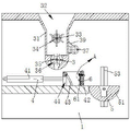
Fig. 1 is a schematic structural view showing the overall structure of a preferred embodiment of a concrete pile manufacturing apparatus according to the present invention;
FIG. 2 is a schematic view of the connection structure of the dosing mechanism, the material delivering mechanism, the turnover mechanism and the vibration mechanism shown in FIG. 1;
FIG. 3 is a schematic view of the dosing mechanism shown in FIG. 2;
FIG. 4 is a schematic structural view of the turnover mechanism shown in FIG. 1;
FIG. 5 is a schematic view of the moving mechanism shown in FIG. 1;
fig. 6 is an enlarged view of the part a shown in fig. 2.
In the figure: 1. the device comprises a main body, 2, a moving mechanism, 21, a first motor, 22, a first rotating shaft, 23, a first gear, 24, a second rotating shaft, 25, a second gear, 26, a roller, 27, a guide rail, 3, a quantifying mechanism, 31, a storage box, 32, a stirring cavity, 33, a third rotating shaft, 34, a stirring wheel, 35, a quantifying wheel, 36, a quantifying groove, 37, a second motor, 38, a belt pulley, 39, a connecting belt, 4, a material delivering mechanism, 41, a telescopic oil cylinder, 42, a moving box, 43, a baffle, 44, a surplus groove, 5, a turnover mechanism, 51, a mold body, 52, a sliding block, 53, a wire column, 54, a third gear, 55, a rack, 56, a fourth gear, 57, a fifth gear, 58, a fourth motor, 6, a vibration mechanism, 61, a vibration plate, 62, a sliding rod, 63, a connecting rod, 64, a rotary table, 65 and a third motor.
Detailed Description
In order to make the technical means, the creation characteristics, the achievement purposes and the effects of the invention easy to understand, the invention is further described with the specific embodiments.
As shown in fig. 1-6, the concrete pile production apparatus according to the present invention includes a main body 1, a moving mechanism 2, a dosing mechanism 3, a material delivering mechanism 4, a turnover mechanism 5 and a vibrating mechanism 6, wherein the dosing mechanism 3 for releasing the concrete quantitatively is disposed inside the main body 1, the material delivering mechanism 4 for filling the concrete into the mold part of the turnover mechanism 5 is disposed inside the main body 1, the vibrating mechanism 6 for compacting the filled concrete is disposed inside the material delivering mechanism 4, the turnover mechanism 5 for releasing the manufactured concrete pile from the mold is disposed inside the main body 1, and the moving mechanism 2 for making a moving space for the finished product is disposed inside the main body 1.
Specifically, the quantitative mechanism 3 includes a storage box 31, a stirring chamber 32, a third rotating shaft 33, a stirring wheel 34, a quantitative wheel 35, a quantitative groove 36, a second motor 37, a belt pulley 38 and a connecting belt 39, the inside of the main body 1 is provided with the storage box 31, the inside of the storage box 31 is provided with the stirring chamber 32, the stirring chamber 32 and the inside of the bottom end of the storage box 31 are respectively rotated by one of the third rotating shaft 33, the third rotating shaft 33 is rotatably connected to the storage box 31, one side of the storage box 31 is provided with the second motor 37, the second motor 37 and the end of the third rotating shaft 33 are respectively fixed with one of the belt pulley 38, a plurality of the belt pulley 38 is wound with the connecting belt 39, the stirring chamber 32 is located inside, the side wall of the third rotating shaft 33 is fixed with the stirring wheel 34, and the other one of the side wall of the third rotating shaft 33 is fixed with the quantitative wheel 35, the inside of ration wheel 35 is equipped with a plurality of ration groove 36, owing to when needing to release the inside material of storage case 31, at first start second motor 37, second motor 37 through belt pulley 38 with connecting band 39 causes two third pivot 33 synchronous rotation, then one of them third pivot 33 drives stirring wheel 34 stirs the inside material of stirring chamber 32, and the other one third pivot 33 utilizes the inside ration groove 36 of ration wheel 35 realizes the ration release material, can delay the concrete caking through setting up of stirring wheel 34, and then can go pass the inside release right amount material of passing mechanism 4, avoid releasing too much waste that causes, improved the result of use of equipment.
Specifically, the material delivering mechanism 4 includes a telescopic cylinder 41, a movable box 42, a baffle 43 and a surplus receiving groove 44, the telescopic cylinder 41 is disposed at the bottom end of the material storage box 31, the movable box 42 is fixed at one end of the telescopic cylinder 41, the bottom end of the movable box 42 slides in the main body 1, the surplus receiving groove 44 is disposed at one side of the movable box 42, and the baffle 43 rotates in the surplus receiving groove 44, since the telescopic cylinder 41 is operated to slide the movable box 42 to the bottom end of the material storage box 31 before the material storage box 31 releases the material, the telescopic cylinder 41 is used again to fill the material into the mold body 51 after the material storage box 31 contains a proper amount of material, when the movable box 42 retracts, the baffle 43 is deflected by the remaining material, so that the material enters the movable box 42, and then the movable box 42 moves the material, the bottom end of the baffle 43 can be used for shoveling away the material left before, so that the material can be delivered to the interior of the mold part of the turnover mechanism 5, the residual material can be actively recycled, and the influence of the residual material on the trafficability of the parts is avoided.
Specifically, the vibration mechanism 6 includes a vibration plate 61, a sliding rod 62, a connecting rod 63, two rotating discs 64 and a third motor 65, the third motor 65 is installed inside a side wall of the moving box 42, two rotating discs 64 are installed at one end of the third motor 65, the two rotating discs 64 respectively rotate inside the moving box 42, and are rotatably connected to the connecting rod 63 between the two rotating discs, one end of the third motor 65 is fixed to an end of one of the rotating discs 64, the sliding rod 62 is rotatably connected to a bottom end of the connecting rod 63, the vibration plate 61 is slidably connected to the moving box 42 through the sliding rod 62, because the moving box 42 is located at a top end of the mold body 51 after the mold body 51 is filled with the moving box 42, the third motor 65 is started, the third motor 65 drives the two rotating discs 64 to rotate, and because the connecting rod 63 is eccentrically rotated on the two rotating discs 64, the rotating disc 64 will cause the bottom end of the vibrating plate 61 to compress the filled concrete back and forth when rotating, so as to compress the material filled in the turnover mechanism 5, thereby improving the quality and forming efficiency of the product.
Specifically, the turnover mechanism 5 includes a mold body 51, a slider 52, a wire column 53, a third gear 54, a rack 55, a fourth gear 56, a fifth gear 57 and a fourth motor 58, the mold body 51 is disposed inside the main body 1, one slider 52 is disposed at each of two ends of the mold body 51, the slider 52 slides inside the main body 1, the wire column 53 is connected to the middle of the slider 52 through a thread, two ends of the wire column 53 extend to the outside of the slider 52, the end of the slider rotates inside the main body 1, the third gear 54 rotates inside the slider 52, one end of the third gear 54 is fixed to the mold body 51, one side of the third gear is engaged with the rack 55, the rack 55 is fixed to the inner wall of the main body 1, the fourth gear 56 is fixed to the top end of the wire column 53, and the fifth gear 57 is engaged with one side of the fourth gear 56, the fourth motor 58 is fixed to the top end of the fifth gear 57, the fourth motor 58 is installed inside the main body 1, after the vibrating mechanism 6 compacts the material inside the mold body 51, the molded concrete pile needs to be separated from the mold body 51, that is, the fourth motor 58 is started, the fourth motor 58 is engaged with the fourth gear 56 through the fifth gear 57 to rotate, the wire column 53 is rotated to cause the sliding block 52 to move towards the bottom end, and the rack 55 on the side, engaged with the third gear 54, of the inner wall of the sliding block 52 rotates, so that the mold body 51 moves towards the bottom end and deflects, and the manufactured concrete pile can be turned over to a position where the concrete pile is convenient to carry, thereby avoiding manual turnover and labor saving.
Specifically, the moving mechanism 2 includes a first motor 21, a first rotating shaft 22, a first gear 23, a second rotating shaft 24, a second gear 25, rollers 26 and a guide rail 27, the first motor 21 is installed at the top end of the main body 1, two ends of the first motor 21 are respectively fixed with one first rotating shaft 22, two guide rails 27 are installed at the bottom end of the main body 1, two rollers 26 roll on the top end of the guide rail 27, one end of one roller 26 and one end of the first rotating shaft 22 are respectively fixed with one first gear 23, one side of each of the two first gears 23 is respectively vertically engaged with one second gear 25, the second rotating shaft 24 is fixed between the two second gears 25, the second rotating shaft 24 rotates inside the side wall of the main body 1, and after a product is separated from the mold body 51, at this time, the first motor 21 is started, the first motor 21 drives one of the first gears 23 to rotate through the two first rotating shafts 22, the first gear 23 drives the second rotating shaft 24 to rotate through the second gear 25, and the second rotating shaft 24 drives the roller 26 to rotate through the other first gear 23 and the second gear 25 again, so that the purpose that the roller 26 moves on the guide rail 27 is achieved, a space for conveniently carrying products can be moved out after the products are demoulded, and the using mode of the equipment is improved.
When the material storage box 31 is used, because the second motor 37 is started firstly when the internal material of the material storage box 31 needs to be released, the second motor 37 causes the two third rotating shafts 33 to synchronously rotate through the belt pulley 38 and the connecting belt 39, one third rotating shaft 33 drives the stirring wheel 34 to stir the material in the stirring cavity 32, the other third rotating shaft 33 utilizes the quantitative groove 36 in the quantitative wheel 35 to realize quantitative material release, the setting of the stirring wheel 34 can delay concrete caking, further, a proper amount of material can be released into the material delivery mechanism 4, the waste caused by excessive release is avoided, the use effect of the equipment is improved, because the telescopic cylinder 41 is operated to slide the moving box 42 to the bottom end of the material storage box 31 before the material storage box 31 releases the material, the telescopic cylinder 41 is used to fill the material into the mould body 51 after the proper amount of material is contained, when the movable box 42 retracts, the baffle 43 is collided and deflected by the left materials, so that the materials enter the interior of the movable box 42, then when the movable box 42 moves raw materials, the bottom end of the baffle 43 can scrape off the left materials, the materials can be delivered to the interior of the mold part of the turnover mechanism 5, the left materials can be actively recycled, the influence of the left materials on the trafficability of parts is avoided, after the movable box 42 is filled in the mold body 51, the movable box 42 is positioned at the top end of the mold body 51, the third motor 65 is started, the third motor 65 drives the two turntables 64 to rotate, the connecting rod 63 is biased to rotate on the two turntables 64, the bottom end of the vibrating plate 61 can be caused to repeatedly compact the filled concrete when the turntables 64 rotate, the materials filled in the interior of the turnover mechanism 5 can be vibrated and compacted, the quality and the forming efficiency of products are improved, and after the materials in the mold body 51 are compacted by the vibrating mechanism 6, then the formed concrete pile is separated from the mould body 51, namely a fourth motor 58 is started, the fourth motor 58 is meshed with a fourth gear 56 through a fifth gear 57 to rotate, the screw column 53 is rotated to enable the slide block 52 to move towards the bottom end, the rack 55 at one side of the third gear 54 meshed with the inner wall of the slide block 52 rotates, the mould body 51 deflects while moving towards the bottom end, the manufactured concrete pile can be turned over to a position convenient to carry, manual turnover is avoided, labor force is saved, after a product is separated from the mould body 51, the first motor 21 is started, the first motor 21 drives one of the first gears 23 to rotate through two first rotating shafts 22, the first gear 23 drives the second rotating shaft 24 to rotate through the second gear 25, the second rotating shaft 24 drives the roller 26 to rotate through the other first gear 23 and the second gear 25 again, therefore, the purpose that the roller 26 moves on the guide rail 27 is achieved, and the space for conveniently carrying products can be moved out after the products are demoulded, so that the using mode of the equipment is improved.
It will be evident to those skilled in the art that the invention is not limited to the details of the foregoing illustrative embodiments, and that the present invention may be embodied in other specific forms without departing from the spirit or essential attributes thereof. The present embodiments are therefore to be considered in all respects as illustrative and not restrictive, the scope of the invention being indicated by the appended claims rather than by the foregoing description, and all changes which come within the meaning and range of equivalency of the claims are therefore intended to be embraced therein. Any reference sign in a claim should not be construed as limiting the claim concerned.
Furthermore, it should be understood that although the present description refers to embodiments, not every embodiment may contain only a single embodiment, and such description is for clarity only, and those skilled in the art should integrate the description, and the embodiments may be combined as appropriate to form other embodiments understood by those skilled in the art.
Claims (2)
1. The utility model provides a concrete pile production facility which characterized in that: the device comprises a main body (1), a moving mechanism (2), a quantifying mechanism (3), a material delivering mechanism (4), a turnover mechanism (5) and a vibrating mechanism (6), wherein the quantifying mechanism (3) for quantitatively releasing concrete is arranged in the main body (1), the material delivering mechanism (4) for filling concrete into a mould part of the turnover mechanism (5) is arranged in the main body (1), the vibrating mechanism (6) for compacting the filled concrete is arranged in the material delivering mechanism (4), the turnover mechanism (5) for reversely buckling and demoulding the manufactured concrete pile is arranged in the main body (1), and the moving mechanism (2) for vacating a moving space for a finished product is arranged in the main body (1);
the quantitative mechanism (3) comprises a storage box (31), a stirring cavity (32), a third rotating shaft (33), a stirring wheel (34), a quantitative wheel (35), a quantitative groove (36), a second motor (37), a belt pulley (38) and a connecting belt (39), the storage box (31) is arranged inside the main body (1), the stirring cavity (32) is arranged inside the storage box (31), the stirring cavity (32) and the inside of the bottom end of the storage box (31) are respectively rotated by one third rotating shaft (33), the third rotating shaft (33) is rotatably connected with the storage box (31), the second motor (37) is arranged on one side of the storage box (31), the end parts of the second motor (37) and the third rotating shaft (33) are respectively fixed with one belt pulley (38), and the connecting belt (39) is wound between the belt pulleys (38), the side wall of the third rotating shaft (33) positioned in the stirring cavity (32) is fixed with the stirring wheel (34), the side wall of the other third rotating shaft (33) is fixed with the quantitative wheel (35), and a plurality of quantitative grooves (36) are arranged in the quantitative wheel (35);
the material delivering mechanism (4) comprises a telescopic oil cylinder (41), a moving box (42), a baffle plate (43) and a surplus collecting groove (44), the telescopic oil cylinder (41) is arranged at the bottom end of the material storage box (31), the moving box (42) is fixed at one end of the telescopic oil cylinder (41), the bottom end of the moving box (42) slides in the main body (1), the surplus collecting groove (44) is arranged on one side of the moving box (42), and the baffle plate (43) rotates in the surplus collecting groove;
the vibration mechanism (6) comprises a vibration plate (61), a sliding rod (62), a connecting rod (63), two rotating discs (64) and a third motor (65), the third motor (65) is installed inside the side wall of the moving box (42), one end of the third motor (65) is provided with the two rotating discs (64), the two rotating discs (64) respectively rotate inside the moving box (42), the two rotating discs are rotatably connected to the connecting rod (63), one end of the third motor (65) is fixed to the end of one of the rotating discs (64), the bottom end of the connecting rod (63) is rotatably connected with the sliding rod (62), and the vibration plate (61) is slidably connected to the moving box (42) through the sliding rod (62);
the turnover mechanism (5) comprises a mold body (51), a sliding block (52), a wire column (53), a third gear (54), a rack (55), a fourth gear (56), a fifth gear (57) and a fourth motor (58), wherein the mold body (51) is arranged in the main body (1), the sliding block (52) is arranged at each of two ends of the mold body (51), the sliding block (52) slides in the main body (1), the wire column (53) is in threaded connection with the middle of the sliding block (52), two ends of the wire column (53) extend to the outside of the sliding block (52), the end of the wire column rotates in the main body (1), the third gear (54) rotates in the sliding block (52), one end of the third gear (54) is fixed on the mold body (51), the rack (55) is meshed with one side of the third gear, and the rack (55) is fixed on the inner wall of the main body (1), the fourth gear (56) is fixed to the top end of the wire column (53), the fifth gear (57) is meshed with one side of the fourth gear (56), the fourth motor (58) is fixed to the top end of the fifth gear (57), and the fourth motor (58) is installed inside the main body (1).
2. A concrete pile production apparatus according to claim 1, wherein: the moving mechanism (2) comprises a first motor (21), a first rotating shaft (22), a first gear (23), a second rotating shaft (24), a second gear (25), rollers (26) and guide rails (27), the first motor (21) is installed at the top end of the main body (1), the first rotating shaft (22) is fixed at two ends of the first motor (21) respectively, the two guide rails (27) are arranged at the bottom end of the main body (1), the two rollers (26) roll on the top ends of the guide rails (27), one first gear (23) is fixed at the end of one roller (26) and the end of the first rotating shaft (22) respectively, the second gear (25) is vertically meshed with one side of each of the two first gears (23), and the second rotating shaft (24) is fixed between the two second gears (25), the second rotating shaft (24) rotates inside the side wall of the main body (1).
Priority Applications (1)
| Application Number | Priority Date | Filing Date | Title |
|---|---|---|---|
| CN202011626233.4A CN112606194B (en) | 2020-12-31 | 2020-12-31 | Concrete pile production facility |
Applications Claiming Priority (1)
| Application Number | Priority Date | Filing Date | Title |
|---|---|---|---|
| CN202011626233.4A CN112606194B (en) | 2020-12-31 | 2020-12-31 | Concrete pile production facility |
Publications (2)
| Publication Number | Publication Date |
|---|---|
| CN112606194A CN112606194A (en) | 2021-04-06 |
| CN112606194B true CN112606194B (en) | 2022-09-23 |
Family
ID=75253022
Family Applications (1)
| Application Number | Title | Priority Date | Filing Date |
|---|---|---|---|
| CN202011626233.4A Active CN112606194B (en) | 2020-12-31 | 2020-12-31 | Concrete pile production facility |
Country Status (1)
| Country | Link |
|---|---|
| CN (1) | CN112606194B (en) |
Families Citing this family (1)
| Publication number | Priority date | Publication date | Assignee | Title |
|---|---|---|---|---|
| CN115162104B (en) * | 2022-08-09 | 2024-03-22 | 新疆生产建设兵团建筑工程科学技术研究院有限责任公司 | Be used for road anti-icing agent to add device |
Citations (8)
| Publication number | Priority date | Publication date | Assignee | Title |
|---|---|---|---|---|
| US3912238A (en) * | 1972-05-29 | 1975-10-14 | Gerard Yves Richard | Process and installation for the distribution, into a mold, by high speed projection, of a granular and/or pulverulent mixture |
| CN102922594A (en) * | 2011-08-11 | 2013-02-13 | 徐水县华光市政建材有限公司 | Concrete member molding machine |
| KR20130051587A (en) * | 2011-11-10 | 2013-05-21 | 이석광 | Manufacture method of concrete piles and concrete piles by using the same |
| CN103737701A (en) * | 2013-12-12 | 2014-04-23 | 宁波诺亚智能设备有限公司 | Block forming machine |
| CN106272904A (en) * | 2016-11-05 | 2017-01-04 | 吉林久盛生态环境科技股份有限公司 | A kind of convertible forming machine for concrete building unit |
| CN106965293A (en) * | 2017-06-01 | 2017-07-21 | 醴陵友立特种陶瓷有限公司 | A kind of ceramic honey comb brick manufacturing equipment |
| CN109465946A (en) * | 2018-11-29 | 2019-03-15 | 德州海天机电科技有限公司 | Laminated board cloth vibration machine |
| CN109648699A (en) * | 2019-01-31 | 2019-04-19 | 武汉龙旗智能自动化设备有限公司 | A kind of small prefabricated components automatic rollover demoulding stacking mechanism of concrete |
-
2020
- 2020-12-31 CN CN202011626233.4A patent/CN112606194B/en active Active
Patent Citations (8)
| Publication number | Priority date | Publication date | Assignee | Title |
|---|---|---|---|---|
| US3912238A (en) * | 1972-05-29 | 1975-10-14 | Gerard Yves Richard | Process and installation for the distribution, into a mold, by high speed projection, of a granular and/or pulverulent mixture |
| CN102922594A (en) * | 2011-08-11 | 2013-02-13 | 徐水县华光市政建材有限公司 | Concrete member molding machine |
| KR20130051587A (en) * | 2011-11-10 | 2013-05-21 | 이석광 | Manufacture method of concrete piles and concrete piles by using the same |
| CN103737701A (en) * | 2013-12-12 | 2014-04-23 | 宁波诺亚智能设备有限公司 | Block forming machine |
| CN106272904A (en) * | 2016-11-05 | 2017-01-04 | 吉林久盛生态环境科技股份有限公司 | A kind of convertible forming machine for concrete building unit |
| CN106965293A (en) * | 2017-06-01 | 2017-07-21 | 醴陵友立特种陶瓷有限公司 | A kind of ceramic honey comb brick manufacturing equipment |
| CN109465946A (en) * | 2018-11-29 | 2019-03-15 | 德州海天机电科技有限公司 | Laminated board cloth vibration machine |
| CN109648699A (en) * | 2019-01-31 | 2019-04-19 | 武汉龙旗智能自动化设备有限公司 | A kind of small prefabricated components automatic rollover demoulding stacking mechanism of concrete |
Also Published As
| Publication number | Publication date |
|---|---|
| CN112606194A (en) | 2021-04-06 |
Similar Documents
| Publication | Publication Date | Title |
|---|---|---|
| US2859502A (en) | Block molding machine | |
| CN111516130B (en) | Wet forming machine | |
| CN110453569B (en) | Retaining wall type curb structure construction machinery | |
| CN107088950B (en) | A kind of rotary-die type concrete product forming machine | |
| CN112606194A (en) | Concrete pile production facility | |
| CN115890899B (en) | A suspended roller cement pipe making machine | |
| CN101638895A (en) | Slope masonry machine with modes of discharging, vibrating and sliding | |
| CN211194285U (en) | Concrete prefabricated section processing equipment | |
| CN210679114U (en) | Six station shaping high-strength concrete goods equipment of wet process | |
| CN219855200U (en) | Concrete centrifugal compaction forming device | |
| CN106696058A (en) | Cement pipe forming device with position changing device | |
| CN206154480U (en) | Convertible concrete member make -up machine | |
| CN101638896A (en) | Large-span multifunctional concrete slope masonry machine | |
| CN201512794U (en) | Row vibration sliding mode sloping surface masonry machine | |
| CN216707874U (en) | Concrete distributing device | |
| CN222407331U (en) | Brick making equipment for buckwheat tea processing | |
| CN219171197U (en) | Material pressing machine | |
| CN215749886U (en) | Evaporate and press aerated concrete casting mould car | |
| CN202106445U (en) | U-shaped plate quick-forming machine | |
| CN101649619B (en) | Large-span efficient multifunctional concrete sloping surface masonry machine | |
| CN219880516U (en) | Material distributing equipment for processing injection molding parts | |
| CN221066661U (en) | Brick press with high applicability | |
| CN205075159U (en) | Can clear away former of mortar of adhesion on last mould | |
| CN220978013U (en) | Concrete placement device for hydraulic engineering building | |
| CN119308199B (en) | Auxiliary stamping concrete construction equipment and concrete stamping construction method |
Legal Events
| Date | Code | Title | Description |
|---|---|---|---|
| PB01 | Publication | ||
| PB01 | Publication | ||
| SE01 | Entry into force of request for substantive examination | ||
| SE01 | Entry into force of request for substantive examination | ||
| TA01 | Transfer of patent application right |
Effective date of registration: 20220826 Address after: 412000 Jiangbian Village, Nanzhou Town, Lukou District, Zhuzhou City, Hunan Province (Room 103, Unit 3, Building B2, Nanzhou Industrial Park, Nanzhou New District) Applicant after: Zhuzhou Lujun New Materials Co.,Ltd. Address before: 314599 Room 402, 3 Dormitories of Wenyuan Road Finance and Taxation Bureau, Wutong Street, Tongxiang City, Jiaxing City, Zhejiang Province Applicant before: Lu Binyan |
|
| TA01 | Transfer of patent application right | ||
| GR01 | Patent grant | ||
| GR01 | Patent grant |