CN112605451A - Glass window production line convenient to section bar cutting - Google Patents
Glass window production line convenient to section bar cutting Download PDFInfo
- Publication number
- CN112605451A CN112605451A CN202011377091.2A CN202011377091A CN112605451A CN 112605451 A CN112605451 A CN 112605451A CN 202011377091 A CN202011377091 A CN 202011377091A CN 112605451 A CN112605451 A CN 112605451A
- Authority
- CN
- China
- Prior art keywords
- cutting
- corner
- plate
- chamfering
- support
- Prior art date
- Legal status (The legal status is an assumption and is not a legal conclusion. Google has not performed a legal analysis and makes no representation as to the accuracy of the status listed.)
- Pending
Links
- 238000005520 cutting process Methods 0.000 title claims abstract description 559
- 239000011521 glass Substances 0.000 title claims abstract description 21
- 238000004519 manufacturing process Methods 0.000 title claims abstract description 17
- 238000003825 pressing Methods 0.000 claims abstract description 56
- 238000007789 sealing Methods 0.000 description 23
- 238000013016 damping Methods 0.000 description 9
- 238000007599 discharging Methods 0.000 description 8
- 239000000463 material Substances 0.000 description 7
- NJPPVKZQTLUDBO-UHFFFAOYSA-N novaluron Chemical compound C1=C(Cl)C(OC(F)(F)C(OC(F)(F)F)F)=CC=C1NC(=O)NC(=O)C1=C(F)C=CC=C1F NJPPVKZQTLUDBO-UHFFFAOYSA-N 0.000 description 7
- 230000000694 effects Effects 0.000 description 5
- 238000010586 diagram Methods 0.000 description 4
- 229910000838 Al alloy Inorganic materials 0.000 description 3
- 238000005096 rolling process Methods 0.000 description 3
- 230000008901 benefit Effects 0.000 description 2
- 238000004140 cleaning Methods 0.000 description 2
- 230000002708 enhancing effect Effects 0.000 description 2
- XAGFODPZIPBFFR-UHFFFAOYSA-N aluminium Chemical compound [Al] XAGFODPZIPBFFR-UHFFFAOYSA-N 0.000 description 1
- 229910052782 aluminium Inorganic materials 0.000 description 1
- 239000004411 aluminium Substances 0.000 description 1
- 238000007664 blowing Methods 0.000 description 1
- 238000010073 coating (rubber) Methods 0.000 description 1
- 230000006835 compression Effects 0.000 description 1
- 238000007906 compression Methods 0.000 description 1
- 238000000034 method Methods 0.000 description 1
- 230000029058 respiratory gaseous exchange Effects 0.000 description 1
- 239000011435 rock Substances 0.000 description 1
- 230000000087 stabilizing effect Effects 0.000 description 1
Images





Classifications
-
- B—PERFORMING OPERATIONS; TRANSPORTING
- B23—MACHINE TOOLS; METAL-WORKING NOT OTHERWISE PROVIDED FOR
- B23D—PLANING; SLOTTING; SHEARING; BROACHING; SAWING; FILING; SCRAPING; LIKE OPERATIONS FOR WORKING METAL BY REMOVING MATERIAL, NOT OTHERWISE PROVIDED FOR
- B23D31/00—Shearing machines or shearing devices covered by none or more than one of the groups B23D15/00 - B23D29/00; Combinations of shearing machines
-
- B—PERFORMING OPERATIONS; TRANSPORTING
- B23—MACHINE TOOLS; METAL-WORKING NOT OTHERWISE PROVIDED FOR
- B23D—PLANING; SLOTTING; SHEARING; BROACHING; SAWING; FILING; SCRAPING; LIKE OPERATIONS FOR WORKING METAL BY REMOVING MATERIAL, NOT OTHERWISE PROVIDED FOR
- B23D19/00—Shearing machines or shearing devices cutting by rotary discs
-
- B—PERFORMING OPERATIONS; TRANSPORTING
- B23—MACHINE TOOLS; METAL-WORKING NOT OTHERWISE PROVIDED FOR
- B23D—PLANING; SLOTTING; SHEARING; BROACHING; SAWING; FILING; SCRAPING; LIKE OPERATIONS FOR WORKING METAL BY REMOVING MATERIAL, NOT OTHERWISE PROVIDED FOR
- B23D33/00—Accessories for shearing machines or shearing devices
- B23D33/02—Arrangements for holding, guiding, and/or feeding work during the operation
Landscapes
- Engineering & Computer Science (AREA)
- Mechanical Engineering (AREA)
- Re-Forming, After-Treatment, Cutting And Transporting Of Glass Products (AREA)
Abstract
The invention discloses a glass window production line convenient for section bar cutting, a cutting support component comprises a cutting base, a cutting support plate and a section bar conveying belt, a cutting positioning component comprises a cutting guide plate, a cutting limit plate, a stop plate, a cutting bracket and a pressing roller, the cutting component comprises a cutting motor, a cutting blade, a cutting cylinder, a return spring and a cutting slide seat, the section bar conveying belt conveys the section bar, the cutting slide base slides downwards to drive the cutting blade to cut through the limiting positions of the cutting guide plate, the cutting limiting plate and the stop plate, after the cutting is finished, the cutting blade can be pulled up by the elastic force of the return spring, so that the next cutting can be carried out, thereby continuously cutting the section, improving the cutting efficiency, stably supporting the section and improving the cutting quality, thereby solve the main artifical problem of supporting the location and cutting and make cutting efficiency reduce of existing equipment.
Description
Technical Field
The invention relates to the field of glass window production equipment, in particular to a glass window production line convenient for section bar cutting.
Background
Aluminum alloy door and window refers to the door and window that adopts the aluminium alloy to make for frame, center pillar, door leaf, and is called aluminium door and window now many times. Compared with doors and windows made of other materials, the aluminum alloy doors and windows have the advantages of light dead weight, high strength, good sealing performance and wide application.
And the section bar is at the in-process of cutting, and to current equipment mainly the manual work support location cut for cutting efficiency reduces.
Disclosure of Invention
The invention aims to provide a glass window production line convenient for section bar cutting, and aims to solve the problem that the cutting efficiency is reduced because the existing equipment mainly supports and positions by manpower for cutting.
In order to achieve the above purpose, the invention provides a glass window production line convenient for section bar cutting, which comprises a cutting machine and an angle cutting machine, wherein the angle cutting machine is positioned at one side of the cutting machine, the cutting machine comprises a cutting support component, a cutting positioning component and a cutting component, the cutting support component comprises a cutting base, a cutting support plate and a section bar conveyer belt, the section bar conveyer belt is rotatably connected with the cutting base and positioned at one side of the cutting base, the cutting support plate is provided with a blanking hole, the cutting support plate is fixedly connected with the cutting base and positioned at one side of the section bar conveyer belt, the cutting positioning component comprises a cutting guide plate, a cutting limit plate, a stop plate, a cutting support and a pressing roller, the cutting guide plate is fixedly connected with the cutting support plate and positioned at one side of the cutting support plate, and the stop plate is fixedly connected with the cutting support plate, and is positioned at one side of the blanking hole, the cutting bracket is fixedly connected with the cutting support plate, and is positioned at one side of the cutting guide plate, the pressing roller is rotationally connected with the cutting bracket, and is positioned at one side of the cutting bracket close to the cutting guide plate, the cutting component comprises a cutting motor, a cutting blade, a cutting cylinder, a return spring and a sliding seat, the sliding seat is connected with the cutting bracket in a sliding way, and is positioned at one side of the cutting bracket, the cutting cylinder is fixedly connected with the cutting bracket, the sliding rod of the cutting cylinder is fixedly connected with the sliding seat, the cutting motor is fixedly connected with the sliding seat, and is positioned at one side of the sliding seat, the cutting blade is rotationally connected with the cutting motor and is positioned at one side of the cutting motor, the return spring is fixedly connected with the sliding seat and is positioned between the sliding seat and the cutting support.
The stop plate comprises a plate body, a second support plate and a cutting adjusting screw rod, the second support plate is fixedly connected with the cutting support plate and is located on one side of the cutting support plate, the plate body is slidably connected with the adjusting support plate and is located on one side, close to the compression roller, of the cutting support plate, and the cutting adjusting screw rod is rotatably connected with the plate body and is in threaded connection with the second support plate.
Wherein, the cutting backup pad has the scale mark, the scale mark evenly distributed is in on the cutting backup pad.
Wherein, the cutting unit still includes guard plate and observation window, the guard plate with slide fixed connection covers cutting blade, the observation window with guard plate fixed connection, and pass the guard plate.
The cutting assembly further comprises a cutting pressing plate, the cutting pressing plate is fixedly connected with the sliding seat and is positioned on one side, close to the cutting supporting plate, of the sliding seat.
Wherein, the corner cutting machine comprises a corner cutting support component, a corner cutting component and a corner cutting positioning component, the corner cutting support component comprises a corner cutting base, a corner cutting conveyer belt, a corner cutting slide plate and a corner cutting cylinder, the corner cutting conveyer belt is rotatably connected with the corner cutting base and is positioned at one side of the corner cutting base, the corner cutting slide plate is slidably connected with the corner cutting base and is positioned at one side of the corner cutting conveyer belt, a slide rod of the corner cutting cylinder is fixedly connected with the corner cutting slide plate and is positioned at one side of the corner cutting base, the corner cutting component comprises a corner cutting support, a corner cutting slide seat, two cutters, two cutter seats, a corner cutting adjusting screw rod and a corner cutting screw rod motor, the corner cutting support is fixedly connected with the corner cutting base and is positioned at one side of the corner cutting base, the corner cutting slide seat is slidably connected with the corner cutting support and is positioned at one side of the corner cutting support, the chamfering adjusting screw is rotatably connected with the chamfering slide seat and penetrates through the chamfering slide seat, the two tool holders are in threaded connection with the chamfering adjusting screw and are in sliding connection with the chamfering slide seat, the two cutters are respectively fixedly connected with the two tool holders and are positioned on one side of the tool holders, the chamfering screw motor is fixedly connected with the chamfering support, a screw of the chamfering screw motor is in threaded connection with the chamfering slide seat, the chamfering positioning component comprises a chamfering guide plate, a second chamfering screw, a first chamfering support plate and a second chamfering support plate, the chamfering guide plate is in sliding connection with the chamfering base and is positioned on one side of the chamfering base, the second chamfering screw is in threaded connection with the chamfering base and is rotatably connected with the chamfering guide plate, and the first chamfering support plate and the second chamfering support plate are provided with a plurality of chamfering holes, the first corner cutting gusset plate and the second corner cutting gusset plate are connected with the corner cutting base in a sliding mode and are positioned on one side close to the corner cutting sliding plate.
The corner cutting support assembly further comprises a corner cutting bin, the corner cutting bin is fixedly connected with the corner cutting base and is located on one side of the corner cutting sliding plate.
The corner cutting assembly further comprises a corner cutting pressing rod, the corner cutting pressing rod is connected with the corner cutting sliding seat in a sliding mode, and the corner cutting pressing rod is located on one side of the corner cutting sliding seat.
The corner cutting assembly further comprises a corner cutting gasket, the corner cutting gasket is fixedly connected with the corner cutting pressing rod and is located on one side of the corner cutting pressing rod.
The tool apron comprises a base body, a rotating block and a locking screw, the rotating block is rotatably connected with the base body and is positioned on one side of the base body, and the locking screw is in threaded connection with the rotating block and the base body and penetrates through the rotating block and the base body.
The invention relates to a glass window production line convenient for cutting profiles, which comprises a cutting base, a cutting support plate and a profile conveyor belt, wherein the profile conveyor belt is rotatably connected with the cutting base and is positioned at one side of the cutting base and used for conveying the profile to be cut, the cutting support plate is provided with a blanking hole, the cut profile can be discharged from the blanking hole, the cutting support plate is fixedly connected with the cutting base and is positioned at one side of the profile conveyor belt, the cutting positioning assembly comprises a cutting guide plate, a cutting limit plate, a stop plate, a cutting bracket and a pressing roller, the cutting guide plate is fixedly connected with the cutting support plate and is positioned at one side of the cutting support plate and used for guiding and limiting the position of the profile, so that the cutting precision can be improved, and the stop plate is fixedly connected with the cutting support plate, the cutting support is fixedly connected with the cutting support plate and is positioned on one side of the cutting guide plate, the pressing roller is rotatably connected with the cutting support and is positioned on one side of the cutting support close to the cutting guide plate, and the cutting support supports the pressing roller to rotate, so that the profile can be pressed, and the cutting precision is improved; the cutting assembly comprises a cutting motor, a cutting blade, a cutting cylinder, a return spring and a cutting slide seat, the slide seat is connected with the cutting support in a sliding manner and is positioned on one side of the cutting support, the cutting cylinder is connected with the cutting support in a fixed manner, a slide rod of the cutting cylinder is connected with the cutting slide seat in a fixed manner, the cutting cylinder can drive the cutting slide seat to move up and down, the cutting motor is connected with the slide seat in a fixed manner and is positioned on one side of the slide seat, the cutting blade is connected with the cutting motor in a rotating manner and is positioned on one side of the cutting motor, the cutting motor is arranged on the slide seat and can drive the cutting blade to rotate, so that a section bar can be cut, the return spring is connected with the slide seat in a fixed manner and is positioned between the slide seat and the cutting support, through return spring's elasticity can with cutting blade is pulled up for can carry out the cutting next time, thereby can cut the section bar in succession, improve cutting efficiency, and can support the section bar steadily, also can improve cutting quality, thereby solve the main artifical problem of cutting that supports the location and make cutting efficiency reduce of holding in the existing equipment.
Drawings
In order to more clearly illustrate the embodiments of the present invention or the technical solutions in the prior art, the drawings used in the description of the embodiments or the prior art will be briefly described below, it is obvious that the drawings in the following description are only some embodiments of the present invention, and for those skilled in the art, other drawings can be obtained according to the drawings without creative efforts.
FIG. 1 is a front block diagram of a cutting machine of a quick clean glazing line of the present invention;
FIG. 2 is a rear view of the cutting machine of a quick clean glazing line of the present invention;
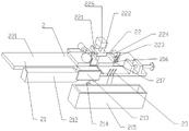
FIG. 3 is a front block diagram of a corner cutting machine of a quick clean glazing line of the present invention;
FIG. 4 is a rear view of the corner cutting machine of a quick clean window production line of the present invention;
FIG. 5 is a bottom block diagram of a corner cutting machine of a quick clean glass window production line of the present invention;
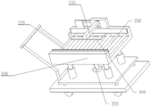
FIG. 6 is a front block diagram of a transfer machine for a quick clean window production line of the present invention;
FIG. 7 is a rear view of the transfer machine of a quick clean window production line of the present invention;
fig. 8 is a schematic cross-sectional view of a transfer machine for a rapid cleaning glazing line of the present invention.
1-cutting machine, 2-corner cutting machine, 3-transferring machine, 11-cutting supporting component, 12-cutting positioning component, 13-cutting component, 111-cutting base, 112-cutting supporting plate, 113-profile conveying belt, 121-cutting guiding plate, 122-cutting limiting plate, 123-stopping plate, 124-cutting bracket, 125-pressing roller, 131-cutting motor, 132-cutting sheet, 133-cutting cylinder, 134-return spring, 135-cutting sliding seat, 136-protecting plate, 137-observing window, 138-cutting pressing plate, 1121-blanking hole, 1122-scale line, 1231-plate body, 1232-second supporting plate, 1233-cutting adjusting screw rod,
21-corner cut supporting component, 22-corner cut component, 23-corner cut positioning component, 211-corner cut base, 212-corner cut conveying belt, 213-corner cut sliding plate, 214-corner cut cylinder, 215-corner cut bin, 216-corner cut pressing rod, 217-corner cut gasket, 221-corner cut bracket, 222-corner cut sliding seat, 223-cutting knife, 224-knife seat, 225-corner cut adjusting screw, 226-corner cut screw motor, 231-corner cut guiding plate, 232-second corner cut screw, 233-first corner cut plate, 234-second corner cut plate, 2331-corner cut hole, 2241-base body, 2242-rotating block, 2243-locking screw,
31-a transfer support component, 32-a vibration reduction component, 33-a transfer emptying component, 311-a transfer table, 312-a roller, 313-a handle, 314-a rolling stop rod, 321-an annular rubber pad, 322-a vibration reduction spring, 323-a sealing plate, 324-a sliding column, 331-a discharge table, 332-a round roller, 333-a height adjusting screw rod, 334-an adjusting hand, 335-a pressing rod, 336-a supporting column, 337-an adjusting gear, 338-a transfer protection plate, 339-a protection pad, 340-a pressing pad, 341-a control rod, 3211-an air hole and 3121-a protrusion.
Detailed Description
Reference will now be made in detail to embodiments of the present invention, examples of which are illustrated in the accompanying drawings, wherein like or similar reference numerals refer to the same or similar elements or elements having the same or similar function throughout. The embodiments described below with reference to the drawings are illustrative and intended to be illustrative of the invention and are not to be construed as limiting the invention.
In the description of the present invention, it is to be understood that the terms "length", "width", "upper", "lower", "front", "rear", "left", "right", "vertical", "horizontal", "top", "bottom", "inner", "outer", and the like, indicate orientations or positional relationships based on the orientations or positional relationships illustrated in the drawings, and are used merely for convenience in describing the present invention and for simplicity in description, and do not indicate or imply that the devices or elements referred to must have a particular orientation, be constructed in a particular orientation, and be operated, and thus, are not to be construed as limiting the present invention. Further, in the description of the present invention, "a plurality" means two or more unless specifically defined otherwise.
Referring to fig. 1 to 8, the present invention provides a glass window production line for conveniently cutting a profile, including:
cutting machine 1, cornering machine 2 and transfer machine 3, cutting machine 1 is including cutting supporting component 11, cutting locating component 12 and cutting component 13, cutting supporting component 11 is including cutting base 111, cutting backup pad 112 and section bar conveyer belt 113, section bar conveyer belt 113 with cutting base 111 rotates to be connected, and is located one side of cutting base 111, cutting backup pad 112 has blanking hole 1121, cutting backup pad 112 with cutting base 111 fixed connection, and is located one side of section bar conveyer belt 113, cutting locating component 12 is including cutting guide plate 121, cutting limiting plate 122, stop board 123, cutting support 124 and compressing roller 125, cutting guide plate 121 with cutting backup pad 112 fixed connection, and be located one side of cutting backup pad 112, stop board 123 with cutting backup pad 112 fixed connection, and is located at one side of the blanking hole 1121, the cutting bracket 124 is fixedly connected to the cutting support plate 112 and is located at one side of the cutting guide plate 121, the pressing roller 125 is rotatably connected to the cutting bracket 124 and is located at one side of the cutting bracket 124 close to the cutting guide plate 121, the cutting assembly 13 includes a cutting motor 131, a cutting blade 132, a cutting cylinder 133, a return spring 134 and a cutting slider 135, the cutting slider 135 is slidably connected to the cutting bracket 124 and is located at one side of the cutting bracket 124, the cutting cylinder 133 is fixedly connected to the cutting bracket 124, a sliding rod of the cutting cylinder 133 is fixedly connected to the cutting slider 135, the cutting motor 131 is fixedly connected to the cutting slider 135 and is located at one side of the cutting slider 135, and the cutting blade 132 is rotatably connected to the cutting motor 131, and is located at one side of the cutting motor 131, and the return spring 134 is fixedly connected with the cutting slide 135 and is located between the cutting slide 135 and the cutting support 124.
In this embodiment, the cutting support assembly 11 includes a cutting base 111, a cutting support plate 112 and a profile conveyer belt 113, the profile conveyer belt 113 is rotatably connected to the cutting base 111 and is located at one side of the cutting base 111 for transporting a profile to be cut, the cutting support plate 112 has a blanking hole 1121, the cut profile can be discharged from the blanking hole 1121, the cutting support plate 112 is fixedly connected to the cutting base 111 and is located at one side of the profile conveyer belt 113, the cutting positioning assembly 12 includes a cutting guide plate 121, a cutting limit plate 122, a stop plate 123, a cutting bracket 124 and a pressing roller 125, the cutting guide plate 121 is fixedly connected to the cutting support plate 112 and is located at one side of the cutting support plate 112 for guiding and limiting the position of the profile, so that the cutting accuracy can be improved, the stop plate 123 is fixedly connected with the cutting support plate 112 and located on one side of the blanking hole 1121, the cutting length of the profile can be limited by the stop plate 123, the cutting bracket 124 is fixedly connected with the cutting support plate 112 and located on one side of the cutting guide plate 121, the pressing roller 125 is rotatably connected with the cutting bracket 124 and located on one side of the cutting bracket 124 close to the cutting guide plate 121, and the cutting bracket 124 supports the pressing roller 125 to rotate, so that the profile can be pressed, and the cutting precision is improved; the cutting assembly 13 comprises a cutting motor 131, a cutting blade 132, a cutting cylinder 133, a return spring 134 and a cutting slide 135135, the slide 135 is slidably connected with the cutting support 124 and is located at one side of the cutting support 124, the cutting cylinder 133 is fixedly connected with the cutting support 124, a sliding rod of the cutting cylinder 133 is fixedly connected with the cutting slide 135135, the cutting cylinder 133 can drive the cutting slide 135 to move up and down, the cutting motor 131 is fixedly connected with the cutting slide 135 and is located at one side of the cutting slide 135, the cutting blade 132 is rotatably connected with the cutting motor 131 and is located at one side of the cutting motor 131, the cutting motor 131 is arranged on the cutting slide 135 and can drive the cutting blade 132 to rotate, so that the cutting action can be performed on the section bar, the return spring 134 is fixedly connected with the slide 135, and is located between the sliding base 135 and the cutting bracket 124, after the cutting is completed, the elastic force of the return spring 134 can pull up the cutting blade 132, so that the next cutting can be performed, the profile can be cut continuously, the cutting efficiency can be improved, the profile can be stably supported, the cutting quality can be improved, and the problem that the cutting efficiency is reduced when the existing equipment mainly manually supports and positions the cutting is solved.
Further, the stop plate 123 includes a plate body 1231, a second support plate 1232 and a cutting adjusting screw 1233, the second support plate 1232 is fixedly connected to the cutting support plate 112 and is located at one side of the cutting support plate 112, the plate body 1231 is slidably connected to the cutting support plate 112 and is located at one side of the cutting support plate 112 close to the pressing roller 125, and the adjusting screw 1233 is rotatably connected to the plate body 1231 and is in threaded connection with the second support plate 1232.
In this embodiment, the adjusting screw 1233 is supported by the second support plate 1232 to rotate and push the plate body 1231 to move, so that the distance between the plate body 1231 and the profile conveyor 113 can be adjusted, and the cutting length can be adjusted to improve the cutting quality.
Further, the cutting support plate 112 has graduation marks 1122, and the graduation marks 1122 are uniformly distributed on the cutting support plate 112.
In an embodiment, the position of the plate body 1231 may be conveniently adjusted by the scale 1122, so that the cutting quality may be improved.
Further, the cutting assembly 13 further includes a protection plate 136 and a viewing window 137, the protection plate 136 is fixedly connected with the sliding base 135 and covers the cutting blade 132, and the viewing window 137 is fixedly connected with the protection plate 136 and penetrates through the protection plate 136.
In this embodiment, the cutting blade 132 can be covered by the protection plate 136, so that the damage to the person caused by the scattered flying of the cutting can be avoided, and the observation window 137 can be conveniently observed inside the protection plate 136.
Further, the cutting assembly 13 further includes a cutting pressing plate 138, and the cutting pressing plate 138 is fixedly connected to the sliding seat 135 and is located on one side of the sliding seat 135 close to the cutting supporting plate 112.
In this embodiment, the cutting pressing plate 138 is disposed on one side of the sliding seat 135, so that when the sliding seat 135 moves down for cutting, the profile can be pressed, and therefore the cutting quality can be improved, and in addition, a spring is disposed between the corner cut pressing rod and the sliding seat 135, so that the pressing effect can be increased, and meanwhile, the blade can be allowed to move continuously when pressed.
Further, the corner cutting machine 2 comprises a corner cutting support component 21, a corner cutting component 22 and a corner cutting positioning component 23, the corner cutting support component 21 comprises a corner cutting base 211, a corner cutting conveyor belt 212, a corner cutting slide plate 213 and a corner cutting cylinder 214, the corner cutting conveyor belt 212 is rotatably connected with the corner cutting base 211 and is positioned at one side of the corner cutting base 211, the corner cutting slide plate 213 is slidably connected with the corner cutting base 211 and is positioned at one side of the corner cutting conveyor belt 212, a slide rod of the corner cutting cylinder 214 is fixedly connected with the corner cutting slide plate 213 and is positioned at one side of the corner cutting base 211, the corner cutting component 22 comprises a corner cutting bracket 221, a corner cutting slide seat 222, two cutters 223, two cutter seats 224, a corner cutting adjusting screw 225 and a corner cutting screw motor 226, the corner cutting bracket 221 is fixedly connected with the corner cutting base 211 and is positioned at one side of the corner cutting base 211, the chamfering slide base 222 is slidably connected to the chamfering support 221 and located on one side of the chamfering support 221, the chamfering adjusting screw 225 is rotatably connected to the chamfering slide base 222 and passes through the chamfering slide base 222, two tool holders 224 are threadedly connected to the chamfering adjusting screw 225 and slidably connected to the chamfering slide base 222, two cutting tools 223 are fixedly connected to the two tool holders 224 and located on one side of the tool holders 224, the chamfering screw motor 226 is fixedly connected to the chamfering support 221, a screw of the chamfering screw motor 226 is threadedly connected to the chamfering slide base 222, the chamfering positioning assembly 23 includes a chamfering guide plate 231, a second chamfering screw 232, a first chamfering plate 233 and a second chamfering plate 234, the chamfering guide plate 231 is slidably connected to the chamfering support 211 and located on one side of the chamfering support 211, the second chamfer screw 232 is screw-coupled to the chamfer base 211 and rotatably coupled to the chamfer guide plate 231, the first and second chamfer plates 233 and 234 each have a plurality of chamfer holes 2331, and the first and second chamfer plates 233 and 234 are slidably coupled to the chamfer base 211 and positioned adjacent to the chamfer slide plate 213.
In this embodiment, the corner cutting support assembly 21 includes a corner cutting base 211, a corner cutting conveyor belt 212, a corner cutting slide plate 213 and a corner cutting cylinder 214, the corner cutting conveyor belt 212 is rotatably connected to the corner cutting base 211 and is located at one side of the corner cutting base 211, so as to convey a profile to be subjected to corner cutting to the corner cutting base 211, the corner cutting slide plate 213 is slidably connected to the corner cutting base 211 and is located at one side of the corner cutting conveyor belt 212, the position of the profile can be defined by the corner cutting slide plate 213, the slide rod of the corner cutting cylinder 214 is fixedly connected to the corner cutting slide plate 213 and is located at one side of the corner cutting base 211, the corner cutting slide plate 213 can be moved by the corner cutting cylinder 214, and the corner cutting assembly 22 includes a corner cutting bracket 221, a corner cutting slide 222, two cutting knives 223, two knife seats 224, a corner cutting adjusting screw 225, A corner cutting screw motor 226, the corner cutting bracket 221 is fixedly connected to the corner cutting base 211 and is located at one side of the corner cutting base 211, the corner cutting slide seat 222 is slidably connected to the corner cutting bracket 221 and is located at one side of the corner cutting bracket 221, the corner cutting bracket 221 is used for supporting the corner cutting slide seat 222 to be capable of sliding up and down, the corner cutting adjusting screw 225 is rotatably connected to the corner cutting slide seat 222 and penetrates through the corner cutting slide seat 222, the corner cutting adjusting screw 225 has two symmetrical end threads, the two tool seats 224 are in threaded connection with the corner cutting adjusting screw 225 and are slidably connected to the corner cutting slide seat 222, the two tool seats 224 can be moved simultaneously to adjust positions by rotating the corner cutting adjusting screw 225, so as to facilitate the corner cutting of profiles with different lengths, and the two cutters 223 are respectively fixedly connected to the two tool seats 224, and is located at one side of the knife holder 224, the cutter 223 is driven by a motor to perform a corner cutting action, the corner cutting screw motor 226 is fixedly connected with the corner cutting bracket 221, the screw of the corner cutting screw motor 226 is in threaded connection with the slide, the slide can be driven to move up and down by starting the corner cutting screw motor 226, so that the blade contacts with the profile to perform cutting, the corner cutting positioning component 23 comprises a corner cutting guide plate 231, a second corner cutting screw 232, a first corner cutting plate 233 and a second corner cutting plate 234, the corner cutting guide plate 231 is in sliding connection with the corner cutting base 211 and is located at one side of the corner cutting base 211, the position of the profile can be limited by the cooperation of the corner cutting guide plate 231 and the corner cutting slide plate 213, so that the corner cutting can be performed more accurately, the second corner cutting screw 232 is in threaded connection with the corner cutting base 211, the first gusset plate 233 and the second gusset plate 234 are both provided with a plurality of gusset holes 2331, the first gusset plate 233 and the second gusset plate 234 are slidably connected with the gusset base 211 and are positioned at one side close to the gusset sliding plate 213, the blade can be allowed to pass through the gusset holes 2331, and the sliding of the first gusset plate 233 and the second gusset plate 234 can be adjusted according to the length of the profile, so that the profile can be accurately cut, the gusset precision and the profile quality are improved, and the problem that the profile quality is reduced due to the fact that manual corner cutting is mostly adopted by existing equipment is solved.
Further, the corner cutting support assembly 21 further comprises a corner cutting box 215, and the corner cutting box 215 is fixedly connected with the corner cutting base 211 and is located on one side of the corner cutting sliding plate 213.
In this embodiment, the corner cut bin 215 is disposed on one side of the corner cut sliding plate 213, so that after the corner cut is completed, the corner cut sliding plate 213 is slid, and the second corner cut screw 232 is rotated, so that the finished product can be pushed out and fall into the corner cut bin 215 by the corner cut guiding plate 231, thereby facilitating the next processing.
Further, the corner cutting assembly 22 further comprises a corner cutting hold-down rod 216, and the corner cutting hold-down rod 216 is slidably connected to the corner cutting slide 222 and is located at one side of the corner cutting slide 222.
In this embodiment, the chamfer pressing rod 216 and the chamfer slide 222 are fixedly connected, so that the chamfer slide 222 can move downwards together, and the profile can be further pressed in the cutting process, so that the chamfer quality can be improved. Additionally, a spring is provided between the corner cut hold down bar 216 and the corner cut slide 222 to increase the hold down effect while still allowing the blade to continue to move during hold down.
Further, the corner cutting assembly 22 further includes a corner cutting gasket 217, and the corner cutting gasket 217 is fixedly connected to the corner cutting pressing rod 216 and is located on one side of the corner cutting pressing rod 216.
In this embodiment, the corner cutting gasket 217 is used to protect the profile from being crushed by the corner cutting pressing rod 216, so as to improve the corner cutting quality.
Further, blade holder 224 includes pedestal 2241, turning block 2242 and locking screw 2243, turning block 2242 with pedestal 2241 rotates to be connected, and is located one side of pedestal 2241, locking screw 2243 with turning block 2242 with pedestal 2241 threaded connection, and pass turning block 2242 with pedestal 2241.
In this embodiment, the turning block 2242 can be relative the pedestal 2241 rotates to can adjust the setting and be in two inclination of cutter 223 on the turning block 2242 for can cut out the section bar of different angles, thereby can enlarge application range, and can also finely tune the angle, make 45 jiaos can set up more accurately, and through rotating locking screw 2243 can be right the turning block 2242 with the pedestal 2241 locks, makes the operation more stable.
Further, the transfer machine 3 includes a transfer support assembly 31, a vibration reduction assembly 32 and a transfer emptying assembly 33, the transfer support assembly 31 includes a transfer table 311, a plurality of rollers 312 and a handle 313, the plurality of rollers 312 are fixedly connected to the transfer table 311 and located on one side of the transfer table 311, the handle 313 is fixedly connected to the transfer table 311 and located on one side of the transfer table 311 away from the rollers 312, the vibration reduction assembly 32 includes an annular rubber pad 321, a plurality of vibration reduction springs 322, a sealing plate 323 and a sliding column 324, the sliding column 324 is slidably connected to the transfer table 311 and located on one side of the transfer table 311 close to the handle 313, the sealing plate 323 is fixedly connected to the sliding column 324 and located on one side of the sliding column 324, the annular rubber pad 321 has an air hole 3211, the annular rubber pad 321 is fixedly connected to the sealing plate 323 and the transfer table 311, the transfer and emptying assembly 33 comprises an emptying platform 331, a plurality of round rollers 332, an elevation screw 333, an adjusting hand 334313, a pressing rod 335, a supporting column 336 and an adjusting gear 337, the elevation screw 333 is rotatably connected with the sealing plate 323 and is located on one side of the sealing plate 323 away from the damping spring 322, the emptying platform 331 is in threaded connection with the elevation screw 333 and is located on one side of the elevation screw 333, the round rollers 332 are rotatably connected with the emptying platform 331 and are located on one side of the emptying platform 331 away from the sealing plate 323, the adjusting gear 337 is rotatably connected with the transfer platform 311 and is engaged with the elevation screw 333, the adjusting hand 334 is fixedly connected with the adjusting gear 337, and is located at one side of the adjusting gear 337, and the pressing rod 335 is slidably connected to the discharging table 331 and is located at one side of the discharging table 331.
In this embodiment, the transferring support assembly 31 includes a transferring platform 311, a plurality of rollers 312 and a handle 313, the plurality of rollers 312 are fixedly connected to the transferring platform 311 and located at one side of the transferring platform 311, so that the transferring platform 311 can be moved conveniently, the handle 313 is fixedly connected to the transferring platform 311 and located at one side of the transferring platform 311 away from the rollers 312, so that the user can push the transferring platform, the damping assembly 32 includes an annular rubber pad 321, a plurality of damping springs 322, a sealing plate 323 and a sliding column 324, the sliding column 324 is slidably connected to the transferring platform 311 and located at one side of the transferring platform 311 close to the handle 313, the sealing plate 323 is fixedly connected to the sliding column 324 and located at one side of the sliding column 324, the sliding column 324 is used for supporting the sealing plate 323 to slide up and down relative to the transferring platform 311, the annular rubber pad 321 has an air hole 3211, the annular rubber pad 321 is fixedly connected to the sealing plate 323 and the transfer table 311 and is located between the sealing plate 323 and the transfer table 311, the annular rubber pad 321 has elasticity and can allow the sealing plate 323 to move up and down in a short distance, and suck in and exhaust air through the air hole 3211 during the up and down movement, and buffer the air, the plurality of damping springs 322 are fixedly connected to the sealing plate 323 and are located between the sealing plate 323 and the transfer table 311, the damping springs 322 are used for enhancing the damping effect and supporting the sealing plate 323 at a certain height so as to move up and down conveniently, the transferring and discharging assembly 33 includes a discharging table 331, a plurality of round rollers 332, a height adjusting screw 333, an adjusting hand 334, a pressing rod 335, a supporting column 336 and an adjusting gear 337, the height-adjusting screw 333 is rotatably connected to the sealing plate 323 and located at a side of the sealing plate 323 away from the damping spring 322, the sealing plate 323 can move up and down by rotating the height-adjusting screw 333, so that the height can be changed according to different conveying lines, so that the loading and unloading can be more conveniently performed, the material-discharging table 331 is threadedly connected to the height-adjusting screw 333 and located at a side of the height-adjusting screw 333, a plurality of round rollers 332 are rotatably connected to the material-discharging table 331 and located at a side of the material-discharging table 331 away from the sealing plate 323, the material-discharging table 331 is used to support the round rollers 332, friction during glass window loading can be reduced by the round rollers 332, so that the loading is more smooth, the adjusting gear 337 is rotatably connected to the transfer table 311 and engaged with the height-adjusting screw 333, and the adjusting hand 334 is fixedly connected to the adjusting gear 337, the adjusting gear 337 can be driven to rotate by the adjusting hand 334, so that the adjusting gear 337 can drive the height-adjusting screw 333 to rotate, the height of the material placing table 331 can be conveniently adjusted, the pressing rod 335 is slidably connected to the material placing table 331 and is located on one side of the material placing table 331, and the pressing rod 335 is used for clamping a glass window. Through set up the ring-shaped rubber pad 321 on the sealing plate 323 with the transfer platform 311, and be provided with gas pocket 3211 on the ring-shaped rubber pad 321, when receiving external vibration, the sealing plate 323 can reciprocate under the support of damping spring 322, through the exhaust of breathing in of gas pocket 3211, simultaneously can be through air with damping spring 322 absorbs vibration, make can make the glass window on the blowing platform 331 places more stably, thereby solve current transfer device and produce easily and rock and collide with, influence the production quality's of product problem.
Further, the transporting and emptying assembly 33 further comprises two transporting protection plates 338 and two protection pads 339, wherein the two transporting protection plates 338 are fixedly connected with the emptying table 331 and located on two sides of the emptying table 331, and the two protection pads 339 are fixedly connected with the two transporting protection plates 338 and located on one side of the transporting protection plates 338.
In this embodiment, the two transportation protection plates 338 are located at two sides of the material placing table 331 to prevent the glass window from sliding off the material placing table, and the two protection pads 339 are made of rubber material to protect the glass window and prevent the glass window from being damaged.
Further, the transferring and emptying assembly 33 further comprises a pressing pad 340, and the pressing pad 340 is fixedly connected with the pressing rod 335 and is located on one side of the pressing rod 335 close to the emptying table 331.
In this embodiment, the pressing pad 340 is used to increase the friction between the pressing rod 335 and the glass window, and make the contact surface softer, so that the glass window can be prevented from being scratched while being clamped.
Further, the transferring and emptying assembly 33 further comprises a control rod 341, and the control rod 341 is fixedly connected with the pressing rod 335 and is located on one side of the pressing rod 335 close to the handle 313.
In this embodiment, the control rod 341 allows the pressing rod 335 to be operated near the handle 313, and a locking rod is further provided at one side of the control rod 341, so that the control rod 341 may be slid down to be locked by the locking rod, thereby stabilizing the fixing.
Further, the transportation support assembly 31 further includes a rolling bar 314, the roller 312 has a protrusion 3121, and the rolling bar is slidably connected to the transportation table 311 and is located on a side of the transportation table 311 close to the protrusion 3121.
In this embodiment, the roller 314 may slide relative to the rotation table, and the roller 312 has a protrusion 3121, so that when a vehicle needs to be parked, the roller 314 may be moved to one side of the roller 312 by pressing down the roller 314, the roller 312 may be limited by the protrusion 3121, so that the rotation of the roller 312 may be limited to achieve the purpose of parking, and for enhancing the effect, a groove may be formed in the roller 314, so that the protrusion 3121 may enter the groove, so that the braking effect may be enhanced.
Through cutting machine 1 cuts the section bar, cornering machine 2 carries out the corner cut to the section bar of appointed length, then can assemble into the window frame, holds and puts into glass through the window frame mould after, through transfer machine 3 carries, and the kludge carries out the rubber coating after, and the cleaning machine washs the glass window, then can pack out goods to can improve production efficiency, reduction in production cost, make the benefit better.
While the invention has been described with reference to a preferred embodiment, it will be understood by those skilled in the art that various changes in form and detail may be made therein without departing from the spirit and scope of the invention as defined by the appended claims.
Claims (10)
1. A glass window production line convenient for section bar cutting is characterized in that,
comprises a cutting machine and an angle cutting machine, wherein the angle cutting machine is positioned at one side of the cutting machine, the cutting machine comprises a cutting supporting component, a cutting positioning component and a cutting component, the cutting supporting component comprises a cutting base, a cutting supporting plate and a profile conveying belt, the profile conveying belt is rotatably connected with the cutting base and positioned at one side of the cutting base, the cutting supporting plate is provided with a blanking hole, the cutting supporting plate is fixedly connected with the cutting base and positioned at one side of the profile conveying belt, the cutting positioning component comprises a cutting guiding plate, a cutting limiting plate, a stopping plate, a cutting support and a pressing roller, the cutting guiding plate is fixedly connected with the cutting supporting plate and positioned at one side of the cutting supporting plate, the stopping plate is fixedly connected with the cutting supporting plate and positioned at one side of the blanking hole, the cutting support is fixedly connected with the cutting supporting plate, and be located one side of cutting guide board, the pinch roller with the cutting support rotates to be connected, and is located the cutting support is close to one side of cutting guide board, cutting assembly is including cutting motor, cutting blade, cutting cylinder, return spring and cutting slide, the cutting slide with cutting support sliding connection, and be located one side of cutting support, the cutting cylinder with cutting support fixed connection, the slide bar of cutting cylinder with cutting slide fixed connection, the cutting motor with cutting slide fixed connection, and be located one side of slide, cutting blade with the cutting motor rotates to be connected, and is located one side of cutting motor, return spring with cutting slide fixed connection, and be located the cutting slide with between the cutting support.
2. A glazing line facilitating profile cutting according to claim 1,
the stop plate comprises a plate body, a second support plate and a cutting adjusting screw rod, the second support plate is fixedly connected with the cutting support plate and is located on one side of the cutting support plate, the plate body is slidably connected with the adjusting support plate and is located on one side, close to the pressing roller, of the cutting support plate, and the cutting adjusting screw rod is rotatably connected with the plate body and is in threaded connection with the second support plate.
3. A glazing line facilitating profile cutting as claimed in claim 2, wherein the cutting support plate has graduations evenly distributed over the cutting support plate.
4. A glazing line facilitating profile cutting according to claim 3,
the cutting assembly further comprises a protection plate and an observation window, the protection plate is fixedly connected with the sliding seat and covers the cutting blade, and the observation window is fixedly connected with the protection plate and penetrates through the protection plate.
5. A glazing line facilitating profile cutting according to claim 4,
the cutting assembly further comprises a cutting pressing plate, and the cutting pressing plate is fixedly connected with the sliding seat and is positioned on one side, close to the cutting supporting plate, of the sliding seat.
6. A glazing line facilitating profile cutting according to claim 1,
the corner cutting machine comprises a corner cutting support component, a corner cutting component and a corner cutting positioning component, wherein the corner cutting support component comprises a corner cutting base, a corner cutting conveyer belt, a corner cutting sliding plate and a corner cutting air cylinder, the corner cutting conveyer belt is rotatably connected with the corner cutting base and is positioned on one side of the corner cutting base, the corner cutting sliding plate is slidably connected with the corner cutting base and is positioned on one side of the corner cutting conveyer belt, a sliding rod of the corner cutting air cylinder is fixedly connected with the corner cutting sliding plate and is positioned on one side of the corner cutting base, the corner cutting component comprises a corner cutting support, a corner cutting sliding seat, two cutters, two cutter seats, a corner cutting adjusting screw rod and a corner cutting screw rod motor, the corner cutting support is fixedly connected with the corner cutting base and is positioned on one side of the corner cutting base, the corner cutting sliding seat is slidably connected with the corner cutting support and is positioned on one side of the corner cutting support, the chamfering adjusting screw is rotatably connected with the chamfering slide seat and penetrates through the chamfering slide seat, the two tool holders are in threaded connection with the chamfering adjusting screw and are in sliding connection with the chamfering slide seat, the two cutters are respectively fixedly connected with the two tool holders and are positioned on one side of the tool holders, the chamfering screw motor is fixedly connected with the chamfering support, a screw of the chamfering screw motor is in threaded connection with the chamfering slide seat, the chamfering positioning component comprises a chamfering guide plate, a second chamfering screw, a first chamfering support plate and a second chamfering support plate, the chamfering guide plate is in sliding connection with the chamfering base and is positioned on one side of the chamfering base, the second chamfering screw is in threaded connection with the chamfering base and is rotatably connected with the chamfering guide plate, and the first chamfering support plate and the second chamfering support plate are provided with a plurality of chamfering holes, the first corner cutting gusset plate and the second corner cutting gusset plate are connected with the corner cutting base in a sliding mode and are positioned on one side close to the corner cutting sliding plate.
7. A glazing line facilitating profile cutting according to claim 6,
the corner cutting support assembly further comprises a corner cutting bin, and the corner cutting bin is fixedly connected with the corner cutting base and is located on one side of the corner cutting sliding plate.
8. A glazing line facilitating profile cutting according to claim 7,
the corner cut assembly further comprises a corner cut pressing rod, the corner cut pressing rod is connected with the corner cut sliding seat in a sliding mode, and the corner cut pressing rod is located on one side of the corner cut sliding seat.
9. A glazing line facilitating profile cutting according to claim 8,
the corner cut assembly further comprises a corner cut gasket, and the corner cut gasket is fixedly connected with the corner cut pressing rod and is located on one side of the corner cut pressing rod.
10. A glazing line facilitating profile cutting according to claim 9,
the tool apron comprises a base body, a rotating block and a locking screw, the rotating block is rotatably connected with the base body and is positioned on one side of the base body, and the locking screw is in threaded connection with the rotating block and the base body and penetrates through the rotating block and the base body.
Priority Applications (1)
| Application Number | Priority Date | Filing Date | Title |
|---|---|---|---|
| CN202011377091.2A CN112605451A (en) | 2020-11-30 | 2020-11-30 | Glass window production line convenient to section bar cutting |
Applications Claiming Priority (1)
| Application Number | Priority Date | Filing Date | Title |
|---|---|---|---|
| CN202011377091.2A CN112605451A (en) | 2020-11-30 | 2020-11-30 | Glass window production line convenient to section bar cutting |
Publications (1)
| Publication Number | Publication Date |
|---|---|
| CN112605451A true CN112605451A (en) | 2021-04-06 |
Family
ID=75228292
Family Applications (1)
| Application Number | Title | Priority Date | Filing Date |
|---|---|---|---|
| CN202011377091.2A Pending CN112605451A (en) | 2020-11-30 | 2020-11-30 | Glass window production line convenient to section bar cutting |
Country Status (1)
| Country | Link |
|---|---|
| CN (1) | CN112605451A (en) |
Cited By (2)
| Publication number | Priority date | Publication date | Assignee | Title |
|---|---|---|---|---|
| CN114682837A (en) * | 2022-05-16 | 2022-07-01 | 虹蚁(杭州)门窗科技有限公司 | An adjustable door and window profile cutting and grooving equipment |
| CN115156622A (en) * | 2022-09-02 | 2022-10-11 | 江苏广坤铝业有限公司 | Aluminium alloy cutting equipment with spark sputtering prevention |
Citations (5)
| Publication number | Priority date | Publication date | Assignee | Title |
|---|---|---|---|---|
| CN204159892U (en) * | 2014-10-10 | 2015-02-18 | 安徽沃佳机床制造有限公司 | A kind of knife rest adjusting device |
| CN104607956A (en) * | 2015-01-06 | 2015-05-13 | 池州共康汽车零部件有限公司 | Boring mill fine-adjustment clamping device |
| CN106180787A (en) * | 2016-07-21 | 2016-12-07 | 广州市双岛科技有限公司 | A kind of construction material perforating device just |
| CN109676173A (en) * | 2019-02-15 | 2019-04-26 | 上海拜杰实业有限公司 | A kind of new type auto puncher |
| CN110935902A (en) * | 2019-12-19 | 2020-03-31 | 安徽臻通网络科技有限公司 | Panel drilling equipment convenient to different apertures processing usefulness |
-
2020
- 2020-11-30 CN CN202011377091.2A patent/CN112605451A/en active Pending
Patent Citations (5)
| Publication number | Priority date | Publication date | Assignee | Title |
|---|---|---|---|---|
| CN204159892U (en) * | 2014-10-10 | 2015-02-18 | 安徽沃佳机床制造有限公司 | A kind of knife rest adjusting device |
| CN104607956A (en) * | 2015-01-06 | 2015-05-13 | 池州共康汽车零部件有限公司 | Boring mill fine-adjustment clamping device |
| CN106180787A (en) * | 2016-07-21 | 2016-12-07 | 广州市双岛科技有限公司 | A kind of construction material perforating device just |
| CN109676173A (en) * | 2019-02-15 | 2019-04-26 | 上海拜杰实业有限公司 | A kind of new type auto puncher |
| CN110935902A (en) * | 2019-12-19 | 2020-03-31 | 安徽臻通网络科技有限公司 | Panel drilling equipment convenient to different apertures processing usefulness |
Cited By (2)
| Publication number | Priority date | Publication date | Assignee | Title |
|---|---|---|---|---|
| CN114682837A (en) * | 2022-05-16 | 2022-07-01 | 虹蚁(杭州)门窗科技有限公司 | An adjustable door and window profile cutting and grooving equipment |
| CN115156622A (en) * | 2022-09-02 | 2022-10-11 | 江苏广坤铝业有限公司 | Aluminium alloy cutting equipment with spark sputtering prevention |
Similar Documents
| Publication | Publication Date | Title |
|---|---|---|
| CN210997114U (en) | Coil stock cutting device for laser cutting machine | |
| CN105800925A (en) | A fully automatic glass slitting line | |
| KR101536639B1 (en) | Apparatus for Cutting a Metal Plate | |
| CN209503814U (en) | Four corner workpiece automatic chamfering lathes | |
| CN209619193U (en) | A glass cutting machine | |
| CN109746690B (en) | Window frame automated production line | |
| CN112605088A (en) | Quick clean glass window production line | |
| CN222819287U (en) | Cutting and grinding machine | |
| CN221695598U (en) | Profile drilling, milling and cutting device | |
| CN220840965U (en) | Cutting and grinding integrated machine | |
| CN221021808U (en) | Cutting and grinding integrated machine | |
| CN220840966U (en) | Sectioning assembly and cutting and grinding integrated machine | |
| CN219503840U (en) | Automatic cutting and discharging device for aluminum profile | |
| CN112570808A (en) | Glass window manufacturing system convenient to section bar corner cut | |
| CN114131680B (en) | Neat and burr-free automobile sun visor lens cutting production line and working method thereof | |
| CN117087021A (en) | Cutting and grinding machine | |
| CN117754749A (en) | Integrated cutting and grinding machine and its control method, media, and computer equipment | |
| CN108994370A (en) | A kind of aluminum profile fully automatic cutting machine | |
| KR101469743B1 (en) | Apparatus for cutting and polishing stone corner | |
| CN221066839U (en) | Cutting and grinding integrated machine | |
| CN220719485U (en) | PP cutting machine | |
| CN220882922U (en) | Cutting and grinding integrated machine | |
| CN220921908U (en) | Grinding device and cutting and grinding integrated machine | |
| CN217889622U (en) | Edging slot milling machine with dust removal function | |
| CN220499336U (en) | Vertical cutting machine with protection architecture |
Legal Events
| Date | Code | Title | Description |
|---|---|---|---|
| PB01 | Publication | ||
| PB01 | Publication | ||
| SE01 | Entry into force of request for substantive examination | ||
| SE01 | Entry into force of request for substantive examination | ||
| WD01 | Invention patent application deemed withdrawn after publication |
Application publication date: 20210406 |
|
| WD01 | Invention patent application deemed withdrawn after publication |