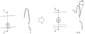
Mechanism and mould suitable for injection moulding product narrow space back-off drawing of patterns
Technical Field
The invention belongs to the field of molds, and particularly relates to a mechanism and a mold suitable for back-off demolding of injection molding products in narrow spaces.
Background
General injection moulding product waits that the plastic cools off solidification after the mould compound die shaping can the drawing of patterns, but some injection moulding product exists the back-off (when looking at the product surface from the die sinking direction, the peak is the benchmark, and the face below can not see, and the face that can not see is the back-off), and the back-off drawing of patterns is more complicated, generally has two kinds of drawing of patterns modes:
the first method is to realize back-off demoulding through a straight top and an inclined top; when demoulding, the straight top drives the product to move, and the inclined top is separated from the inverted buckling area of the product. But has the following disadvantages: the mold has a complex structure, so that the manufacturing cost is high, and the production stability of the mold can be reduced; when the structure of the product is narrow, the straight ejection and the inclined ejection can be thin steel in different degrees (the thin steel is in a region that the thickness/height of the die steel is less than or equal to 0.5, the steel material is too thin, the strength is insufficient, and the die is easy to crack), the service life of the die is shortened, the fault risk is increased, and the requirement of the inclined ejection on the motion space can not be met under extreme conditions.
The other is to directly eject and demould by a thimble, also called forced demoulding; when demoulding, the product is ejected out by the ejector pin, and the elastic deformation of the plastic part is utilized to separate the back-off area. But has the following disadvantages: the product reverse buckling area is forcibly pulled, deformed and separated to cause strain injury; the ejector pin in the product back-off area has large ejection resistance and can be ejected forcibly, so that the external wounds such as whitetops, bulges and the like can be left on the inner surface and the outer surface of the product; the die can not be used on a die with high requirements on product appearance, and the application range is narrow.
Disclosure of Invention
The invention aims to provide a mechanism and a die suitable for back-off demoulding of injection products in narrow space, which avoid product trauma caused by forced demoulding, protect the safety of the die, improve the stability of efficient production of the die and avoid the problem of thin steel.
The technical scheme adopted by the invention is as follows:
a mechanism suitable for back-off demoulding of injection molding products in narrow spaces comprises an inclined drawing block moving assembly and a draw hook moving assembly, wherein the mould opening direction is taken as the Z direction, the Z direction is perpendicular to the Z direction, and the direction for pulling the back-off to deform along with demoulding is taken as the Y direction; the inclined drawing block moving assembly comprises a Y-direction guide rail, an inclined drawing block in sliding fit with the guide rail, an inclined guide post matched with the inclined drawing block, a limiting block and a first spring, the inclined drawing block is attached to the outer surface of a product back-off region in an initial state, the inclined drawing block can be driven to move along the + Y direction when moving along the + Z direction along with the front die, the inclined drawing block is extremely limited when moving to the limiting block along the + Y direction, and the first spring always exerts a force in the + Y direction on the inclined drawing block and can ensure that the inclined drawing block is kept at the limit position; the draw hook motion assembly comprises a Y-direction guide rail, a draw hook in sliding fit with the guide rail, a pull rod fixedly connected with the draw hook and a second spring, the draw hook is attached to the inner surface of a product back-off area in an initial state, the inclined drawing block can drive the draw hook to move to the maximum limit through the pull rod after moving for a certain distance in the Y direction, and the second spring always applies a force in the Y direction to the draw hook and can ensure that the position of the draw hook is kept when the draw hook moves independently in the initial state and the inclined drawing block.
Furthermore, the first spring is a spring between the inclined pulling block and the die B plate, and is used for always applying-Y-direction pressure to the die B plate and applying + Y-direction pulling force to the inclined pulling block.
Furthermore, a second spring is a spring acting between the draw hook and the inclined drawing block and always applies Y-direction pressure to the draw hook and + Y-direction pressure to the inclined drawing block.
Furthermore, one end of the pull rod in the-Y direction penetrates through the inclined drawing block and then is connected to the draw hook in a threaded mode, and the inclined drawing block moves for a certain distance in the + Y direction and then drives the draw hook to move to the limit position together through one end of the pull rod in the + Y direction.
Further, the back-off angle of the product is below 30 degrees.
Furthermore, all glue position surfaces on the inclined pulling blocks are designed with die drawing angles.
The utility model provides a mould suitable for injection moulding product narrow space back-off drawing of patterns, includes above-mentioned mechanism that is applicable to injection moulding product narrow space back-off drawing of patterns.
Further, at least two groups of mechanisms suitable for the reverse-buckling demolding of the injection molding product in the narrow space are provided.
The invention has the beneficial effects that:
the mechanism can pull the back-off deformation to be the smooth demoulding in a narrow space so as to carry out the back-off demoulding, the surface of a product is protected, the inclined drawing block moves in advance of the draw hook, and enough space is reserved in the middle, so that the product is ensured not to interfere with the mechanism all the time when being overturned and deformed and demoulded, and the product injury caused by forced demoulding is avoided; the mechanism ensures that the inclined drawing block and the draw hook are fully limited in the motion direction through the action of the spring I, the spring II, the limiting block and the pull rod, ensures that the positions have uniqueness, and protects the safety of a mold; the mechanism is driven by the action of opening and closing the die, and does not need to be additionally driven by an oil cylinder or an ejection mechanism, so that the energy consumption is reduced, and the stability of efficient production of the die is improved; the mechanism has the advantages of simple structure, small occupied space and no thin steel problem.
Drawings
FIG. 1 is a schematic illustration of a product in an embodiment of the invention.
Fig. 2 is a cross-sectional view a-a of fig. 1.
FIG. 3 is a schematic view of a mold suitable for reverse demolding in a narrow space of an injection molded product according to an embodiment of the present invention.
Fig. 4 is a partial structural view of fig. 3, in which a partial structure of a mechanism suitable for reverse mold release in a narrow space of an injection molded product is hidden for the convenience of observation.
FIG. 5 is a first partial view of a mold for reverse demolding in a narrow space of an injection molded product according to an embodiment of the present invention.
Fig. 6 is a cross-sectional view taken along line D-D in fig. 5, showing the start of the mold opening operation.
Fig. 7 is a cross-sectional view taken along line D-D in fig. 5, showing the end of the mold opening operation.
FIG. 8 is a partial view of a mold for reverse demolding in a narrow space of an injection molded product according to an embodiment of the present invention.
Fig. 9 is a sectional view of E-E in fig. 8, showing a state where the mold opening operation is started.
Fig. 10 is a cross-sectional view E-E of fig. 8, just after the diagonal draw block has been moved to the draw bar position.
Fig. 11 is a cross-sectional view taken along line E-E in fig. 8, showing the end of the mold opening operation.
Fig. 12 is a cross-sectional view E-E of fig. 8, in a product ejection state.
Fig. 13 is an inverted angle of the inverted region of the product in an embodiment of the invention.
In the figure: a-an outer surface; b-an inner surface; c-a back-off region; b-a mechanism suitable for back-off demoulding of injection products in narrow space; c, a rear mold core; 1-obliquely drawing a block; 2-an inclined guide post; 3-a guide rail of the inclined drawing block moving assembly; 4-a limiting block; 5, a first spring; 6, pulling a hook; 7-spring two; 8-a pull rod; 9-a guide rail of the drag hook movement component; 10-products.
Detailed Description
The invention is further described below with reference to the figures and examples.
As shown in fig. 1 and fig. 2, which are schematic views of a product 10 according to an embodiment of the present invention, an outer surface a of the product is covered with leather grains, and two screw installation seats have an inverted area c in a mold opening direction, so that the product 10 cannot be directly taken out of a mold cavity after mold opening.
As shown in fig. 3 and 4, a mold suitable for reverse-buckling demolding in narrow space of injection-molded product, includes a mechanism B suitable for reverse-buckling demolding in narrow space of injection-molded product, and the number and arrangement of the mechanism B suitable for reverse-buckling demolding in narrow space of injection-molded product are set according to actual needs, in this embodiment, two sets are adopted.
As shown in fig. 5 to 12, a mechanism B suitable for back-off demolding of injection molding products in narrow spaces comprises an inclined pulling block moving assembly and a hook moving assembly, wherein the mold opening direction is the Z direction, the direction is perpendicular to the Z direction, and the direction for pulling back-off deformation to be in the mold demolding direction is the Y direction; the inclined drawing block moving assembly comprises a Y-direction guide rail 3, an inclined drawing block 1 in sliding fit with the guide rail 3, an inclined guide post 2 matched with the inclined drawing block 1, a limiting block 4 and a first spring 5, the inclined drawing block 1 is attached to the outer surface a of a product back-off region c in an initial state, the inclined drawing block 1 can be driven to move in the + Y direction when the inclined drawing block 2 moves along the + Z direction along with a front die, the inclined drawing block 1 is extremely limited when moving to the limiting block 4 along the + Y direction, and the first spring 5 always exerts a force in the + Y direction on the inclined drawing block 1 and can ensure that the inclined drawing block 1 is kept at the extreme position; the draw hook motion assembly comprises a Y-direction guide rail 9, a draw hook 6 in sliding fit with the guide rail 9, a pull rod 8 and a second spring 7, wherein the pull rod 8 and the second spring 7 are fixedly connected with the draw hook 6, the draw hook 6 is attached to the inner surface b of the product back-off region c in an initial state, the inclined pumping block 1 can drive the draw hook 6 to move to the maximum limit through the pull rod 8 after moving for a certain distance along the direction + Y, and the second spring 7 always applies a force to the draw hook 6 along the direction-Y and can ensure the position maintenance of the draw hook 6 in the initial state and when the inclined pumping block 1 moves. The mechanism can pull the back-off deformation to be the smooth demoulding in a narrow space so as to carry out the back-off demoulding, the surface of a product is protected, the inclined drawing block 1 moves before the draw hook 6, enough space is reserved in the middle, the product 10 is ensured not to interfere with the mechanism all the time when being overturned to deform and demoulded, and the product 10 is prevented from being damaged by forced demoulding; the mechanism ensures that the inclined drawing block 1 and the drag hook 6 are fully limited in the motion direction through the action of the spring I5, the spring II 7, the limiting block 4 and the pull rod 8, ensures that the positions have uniqueness, and protects the safety of a mold; the mechanism is driven by the action of opening and closing the die, and does not need to be additionally driven by an oil cylinder or an ejection mechanism, so that the energy consumption is reduced, and the stability of efficient production of the die is improved; the mechanism has the advantages of simple structure, small occupied space and no thin steel problem.
As shown in fig. 9 to 11, in this embodiment, one end of the pull rod 8 in the-Y direction passes through the inclined pulling block 1 and then is connected to the pull hook 6 by a thread, the inclined pulling block 1 moves a certain distance in the + Y direction and then drives the pull hook 6 to move to the limit position together through one end of the pull rod 8 in the + Y direction, and the pull rod 8 is convenient to process and install.
As shown in fig. 13, in the present embodiment, the reverse angle of the product 10 is below 30 degrees, which facilitates ejection of the product 10.
In this embodiment, the first spring 5 is a spring between the inclined pulling block 1 and the die B plate, and always applies-Y-direction pressure to the die B plate, and applies + Y-direction tension to the inclined pulling block 1, and the second spring 7 is a spring acting between the drag hook 6 and the inclined pulling block 1, and always applies-Y-direction pressure to the drag hook 6, and applies + Y-direction pressure to the inclined pulling block 1, so that the layout is reasonable, the space is saved, and the installation is convenient.
In this embodiment, the glue position surfaces on the inclined pulling block 1 are all designed with a pattern drawing angle, so as to avoid the product 10 from being stuck on the inclined pulling block 1 to cause trauma.
In this embodiment, when the inclined pulling block 1 moves by 28mm, the inclined pulling block 1 contacts with the limit block 4 to reach a limit position, wherein when the inclined pulling block 1 moves by 16mm, the inclined pulling block contacts with the pull rod 8 and drives the pull rod 8 to pull the drag hook 6 to move, and the stroke of the drag hook 6 is 12 mm.
It will be understood that modifications and variations can be made by persons skilled in the art in light of the above teachings and all such modifications and variations are intended to be included within the scope of the invention as defined in the appended claims.