CN112588930A - Internal stay formula work piece processingequipment - Google Patents
Internal stay formula work piece processingequipment Download PDFInfo
- Publication number
- CN112588930A CN112588930A CN202011273948.6A CN202011273948A CN112588930A CN 112588930 A CN112588930 A CN 112588930A CN 202011273948 A CN202011273948 A CN 202011273948A CN 112588930 A CN112588930 A CN 112588930A
- Authority
- CN
- China
- Prior art keywords
- lifting
- workpiece
- base
- work piece
- forming
- Prior art date
- Legal status (The legal status is an assumption and is not a legal conclusion. Google has not performed a legal analysis and makes no representation as to the accuracy of the status listed.)
- Pending
Links
- 238000003825 pressing Methods 0.000 claims description 7
- 125000006850 spacer group Chemical group 0.000 claims description 2
- 238000007493 shaping process Methods 0.000 description 7
- 238000005242 forging Methods 0.000 description 5
- 238000010586 diagram Methods 0.000 description 4
- 238000000034 method Methods 0.000 description 4
- 238000010438 heat treatment Methods 0.000 description 3
- 239000002184 metal Substances 0.000 description 3
- 238000003754 machining Methods 0.000 description 2
- 239000000463 material Substances 0.000 description 2
- 230000003466 anti-cipated effect Effects 0.000 description 1
- 230000002337 anti-port Effects 0.000 description 1
- 238000005452 bending Methods 0.000 description 1
- 238000005516 engineering process Methods 0.000 description 1
- 238000000465 moulding Methods 0.000 description 1
- 229920000098 polyolefin Polymers 0.000 description 1
- 239000004800 polyvinyl chloride Substances 0.000 description 1
- 229920000915 polyvinyl chloride Polymers 0.000 description 1
- 238000004080 punching Methods 0.000 description 1
- 238000010008 shearing Methods 0.000 description 1
- 229920001169 thermoplastic Polymers 0.000 description 1
- 239000004416 thermosoftening plastic Substances 0.000 description 1
Images



Classifications
-
- B—PERFORMING OPERATIONS; TRANSPORTING
- B21—MECHANICAL METAL-WORKING WITHOUT ESSENTIALLY REMOVING MATERIAL; PUNCHING METAL
- B21D—WORKING OR PROCESSING OF SHEET METAL OR METAL TUBES, RODS OR PROFILES WITHOUT ESSENTIALLY REMOVING MATERIAL; PUNCHING METAL
- B21D22/00—Shaping without cutting, by stamping, spinning, or deep-drawing
- B21D22/14—Spinning
- B21D22/16—Spinning over shaping mandrels or formers
-
- B—PERFORMING OPERATIONS; TRANSPORTING
- B21—MECHANICAL METAL-WORKING WITHOUT ESSENTIALLY REMOVING MATERIAL; PUNCHING METAL
- B21D—WORKING OR PROCESSING OF SHEET METAL OR METAL TUBES, RODS OR PROFILES WITHOUT ESSENTIALLY REMOVING MATERIAL; PUNCHING METAL
- B21D51/00—Making hollow objects
- B21D51/16—Making hollow objects characterised by the use of the objects
- B21D51/18—Making hollow objects characterised by the use of the objects vessels, e.g. tubs, vats, tanks, sinks, or the like
Landscapes
- Engineering & Computer Science (AREA)
- Mechanical Engineering (AREA)
- Jigs For Machine Tools (AREA)
Abstract
The invention is suitable for the technical field of forming equipment, and particularly relates to an internal support type workpiece processing device which comprises a base, a lifting assembly, a rotating assembly and an internal support assembly, wherein the lifting assembly is fixedly arranged at the upper end of the base, the rotating assembly is arranged on the base, the internal support assembly is connected with the lifting assembly and used for driving a workpiece to deform outwards from the inside of the workpiece, the lifting assembly is used for driving the internal support assembly to lift in the workpiece, and the rotating assembly is used for clamping the workpiece and driving the workpiece to rotate. The internally-supporting workpiece processing device provided by the embodiment of the invention has a simple structure and is reasonable in design, and any part of the workpiece is formed and processed by extending the workpiece into the workpiece from the opening side of the workpiece and then carrying out internally-supporting forming operation on the part to be processed, so that the workpiece is processed more flexibly, and the processed workpiece is more attractive.
Description
Technical Field
The invention belongs to the technical field of forming equipment, and particularly relates to an internal support type workpiece processing device.
Background
Forming is a process of shaping a workpiece with a forming tool that matches the final surface profile of the workpiece.
Cold forming refers to the processing modes of punching, shearing, bending, stretching and the like of a material without heating, and is called cold forming; the hot forming process is a special process for making thermoplastic sheet into various products, and is characterized by that the sheet material is clamped on the frame, heated to softening state, under the action of external force, made to be tightly attached to the mould surface, cooled and formed so as to obtain the invented product. Polyvinyl chloride, polyolefin, etc. are formed in various ways, and are combined or improved based on three methods, i.e. vacuum, air pressure or mechanical pressure. Cold forming and hot forming are primarily directed to forging. The forging and forming of the workpiece blank under the non-heating state is the cold forming, the forging and forming under the heating state is the hot forming, and the hot forming is divided into warm forging and hot forging, and the temperature is different.
In the existing processing, the metal cup is generally of a standard cylindrical structure. The diameter of the opening end of a small number of metal cups is slightly larger, because the diameter of the forming convex die is larger, only one end of each cup can be formed, the forming convex die cannot extend into the cup, and the forming operation is performed on the middle position of the cup, which is why the common cups only have different diameters at one end. There is a need for a device that can perform a forming operation in the middle of a cup.
Disclosure of Invention
The embodiment of the invention aims to provide an inner supporting type workpiece processing device, and aims to solve the problems in the background technology.
The embodiment of the invention is realized in such a way that the internal support type workpiece processing device comprises a base, a lifting assembly, a rotating assembly and an internal support assembly, wherein the lifting assembly is fixedly arranged at the upper end of the base, the rotating assembly is arranged on the base, the internal support assembly is connected with the lifting assembly and is used for driving a workpiece to deform outwards from the inside of the workpiece, the lifting assembly is used for driving the internal support assembly to lift in the workpiece, and the rotating assembly is used for clamping the workpiece and driving the workpiece to rotate.
Preferably, the inner support assembly comprises a support plate, a driving screw rod, a wedge block, a hollow shaft and a forming block, the support plate is connected with the lifting assembly and driven by the lifting assembly, the hollow shaft is fixed at the lower end of the support plate, a forming motor is fixed at the upper end of the support plate, the driving screw rod is fixed on a rotating shaft of the forming motor, one end of the driving screw rod, far away from the forming motor, is rotatably connected with the bottom of an inner cavity of the hollow shaft, one side of the forming block is arc-shaped, the other side of the forming block is provided with a hollow cylinder, sleeves are arranged on two sides of the outer diameter of the hollow shaft, the hollow cylinder is slidably arranged in the sleeves, a tension spring is fixed at the core of the hollow cylinder, one end of the tension spring, far away from the forming block, is fixedly connected with the sleeves, slotted holes are arranged at, the semicircular thread sleeve is arranged in the groove hole in a sliding mode, and one side, far away from the inclined plane, of the semicircular thread sleeve is connected with the driving screw rod in a matched mode.
Preferably, a cushion block is fixed at one end of the hollow shaft, which is far away from the supporting plate.
Preferably, the rotating assembly includes the carousel, the dead lever, the clamp plate, rotating electrical machines and electric putter, the carousel rotates the upper end that sets up at the base, rotating electrical machines rotates the bottom that sets up at the base, and be used for driving the carousel and rotate, the level is provided with the mounting groove in the carousel, the dead lever symmetry is provided with two sets ofly, and be "[" type, the lower extreme of dead lever slides and sets up in the mounting groove, and the other end rotates and is connected with the clamp plate, the one end that two sets of dead levers are close to each other all rotates and is connected with the connecting rod, the equal fixedly connected with pressure spring of one end that two sets of dead levers kept away from each other, electric putter fixes the middle part at the mounting groove.
Preferably, one end of the pressing plate, which is far away from the fixing rod, is provided with an anti-slip layer.
Preferably, the lifting assembly comprises a top plate, a lifting motor and at least two groups of lifting guide pillars, the upper end and the lower end of each lifting guide pillar are fixedly connected with the top plate and the base respectively, the lifting motor is fixed at the upper end of the top plate, a lifting screw rod is further rotatably arranged between the top plate and the base and driven by the lifting motor, and the inner support assembly is connected with the lifting screw rod in a matched manner and is in sliding connection with the lifting guide pillars.
Preferably, the bottom of the base is provided with a support leg.
The internally-supporting workpiece processing device provided by the embodiment of the invention has a simple structure and is reasonable in design, and any part of the workpiece is formed and processed by extending the workpiece into the workpiece from the opening side of the workpiece and then carrying out internally-supporting forming operation on the part to be processed, so that the workpiece is processed more flexibly, and the processed workpiece is more attractive.
Drawings
Fig. 1 is a schematic structural diagram of an inner supporting type workpiece processing apparatus according to an embodiment of the present invention;
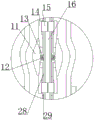
FIG. 2 is an enlarged view of a portion of FIG. 1 at A;
FIG. 3 is an enlarged view of a portion of FIG. 1 at B;
fig. 4 is a schematic structural diagram of an inner-supporting type workpiece processing apparatus according to an embodiment of the present invention;
fig. 5 is a schematic structural diagram of a wedge provided in an embodiment of the present invention.
In the drawings: 1. a base; 2. a top plate; 3. a lifting motor; 4. a lifting guide post; 5. a support plate; 6. fixing the rod; 7. pressing a plate; 8. a pressure spring; 9. a turntable; 10. a workpiece; 11. forming a block; 12. a tension spring; 13. a sleeve; 14. a wedge block; 15. a semicircular internal thread sleeve; 16. driving the screw rod; 17. a guide wheel; 18. a sliding sleeve; 19. an internal thread sleeve; 20. a guide groove; 21. a screw rod sleeve; 22. molding the motor; 23. a rotating electric machine; 24. a support leg; 25. an electric push rod; 26. jacking and sleeving; 27. a connecting rod; 28. a hollow shaft; 29. a slot; 30. and a lifting screw rod.
Detailed Description
In order to make the objects, technical solutions and advantages of the present invention more apparent, the present invention is described in further detail below with reference to the accompanying drawings and embodiments. It should be understood that the specific embodiments described herein are merely illustrative of the invention and are not intended to limit the invention.
Specific implementations of the present invention are described in detail below with reference to specific embodiments.
As shown in fig. 1, a schematic structural diagram of an internal supporting type workpiece processing apparatus provided in an embodiment of the present invention includes a base 1, a lifting assembly, a rotating assembly and an internal supporting assembly, where the lifting assembly is fixedly disposed at an upper end of the base 1, the rotating assembly is disposed on the base 1, the internal supporting assembly is connected to the lifting assembly and is used for driving the workpiece 10 to deform outwards from inside of the workpiece 10, the lifting assembly is used for driving the internal supporting assembly to lift inside of the workpiece 10, and the rotating assembly is used for clamping the workpiece 10 and driving the workpiece 10 to rotate.
In an example of the present invention, for a common metal cup-shaped workpiece, in order to facilitate holding and increase the capacity of the cup, the diameter of the opening end of the cup is generally expanded by using a punch, but the structure of the punch is fixed, so that the punch cannot extend into the middle of the workpiece 10, and thus the cup-shaped workpiece with the variable diameter in the middle cannot be manufactured. When using, earlier drive the internal stay subassembly through lifting unit and go up and down, until the internal stay subassembly is whole to be higher than work piece 10, then utilize rotating assembly to fix work piece 10, and then under lifting unit's drive, the internal stay subassembly stretches into in the work piece 10 gradually, when reacing anticipated position, the internal stay subassembly carries out internal stay formula contour machining to work piece 10 through the reducing, make work piece 10 middle part diameter expansion, after processing is accomplished, the internal stay subassembly reducing once more, thereby conveniently deviate from in the work piece 10, in the course of working, utilize rotating assembly to drive work piece 10 and rotate, thereby the substep carries out the contour machining operation to work piece 10. The internally-supporting workpiece processing device provided by the embodiment of the invention has a simple structure and is reasonable in design, and by extending into the workpiece 10 from the opening side of the workpiece 10 and then carrying out internally-supporting forming operation on the part to be processed, the forming processing on any part of the workpiece 10 is realized, so that the processing on the workpiece 10 is more flexible, and the processed workpiece 10 is more attractive.
As shown in fig. 1, 2, 4 and 5, as a preferred embodiment of the present invention, the inner support assembly includes a support plate 5, a driving screw 16, a wedge 14, a hollow shaft 28 and a forming block 11, the support plate 5 is connected with the lifting assembly and is driven by the lifting assembly, the hollow shaft 28 is fixed at the lower end of the support plate 5, the upper end of the support plate 5 is fixed with a forming motor 22, the driving screw 16 is fixed on the rotating shaft of the forming motor 22, one end of the driving screw 16 far away from the forming motor 22 is rotatably connected with the bottom of the inner cavity of the hollow shaft 28, one side of the forming block 11 is arc-shaped, the other side is provided with a hollow cylinder, two sides of the outer diameter of the hollow shaft 28 are provided with a sleeve 13, the hollow cylinder is slidably arranged in the sleeve 13, the core of the hollow cylinder is fixed with a tension spring 12, one end of the tension spring 12 far away from the forming block 11 is, one side of the wedge block 14 is provided with a semicircular thread sleeve 15, the other side of the wedge block is provided with an inclined plane, the inclined plane is used for abutting against the end part of the forming block 11, the semicircular thread sleeve 15 is arranged in the slotted hole 29 in a sliding mode, and one side, far away from the inclined plane, of the semicircular thread sleeve 15 is connected with the driving screw rod 16 in a matched mode.
As shown in fig. 1, 2, 4 and 5, as a preferred embodiment of the present invention, a spacer is fixed to an end of the hollow shaft 28 remote from the support plate 5.
In one embodiment of the present invention, when in use, the lifting assembly drives the supporting plate 5 to ascend until the hollow shaft 28 is entirely higher than the workpiece 10, then the rotating assembly is used to fix the workpiece 10, and further under the driving of the lifting assembly, the hollow shaft 28 gradually extends into the workpiece 10 until the pad abuts against the bottom of the inner cavity of the workpiece 10, at this time, the forming motor 22 is started, the forming motor 22 drives the driving screw rod 16 to rotate, because the semicircular thread sleeve 15 is arranged on one side of the wedge block 14, and the semicircular thread sleeve 15 is connected with the driving screw rod 16 in a matching manner, during the rotation of the driving screw rod 16 driven by the forming motor 22, the two groups of wedge blocks 14 on the same side of the hollow shaft 28 will slide relative to the outer diameter of the hollow shaft 28, and because the inclined plane on the wedge block 14 abuts against the forming block 11, the hollow cylinder fixed on the forming block, until the one side that the hollow cylinder was kept away from to shaping piece 11 offsets with the internal diameter of work piece 10, shaping motor 22 continues to rotate, the piece 10 is extruded through passing through of shaping piece 11, make work piece 10 outwards take place to warp, after single shaping, shaping motor 22 antiport, shaping piece 11 breaks away from work piece 10, then through lifting unit and rotating assembly cooperation, make work piece 10 rotatory certain angle, then repeat above-mentioned step can, until finishing, after processing, lifting unit drives hollow shaft 28 through backup pad 5 and breaks away from work piece 10.
As shown in fig. 1 and 4, as a preferred embodiment of the present invention, the rotating assembly includes a turntable 9, a fixing rod 6, a pressing plate 7, a rotating motor 23, and an electric push rod 25, the turntable 9 is rotatably disposed at the upper end of the base 1, the rotating motor 23 is rotatably disposed at the bottom of the base 1, and is used for driving the rotary table 9 to rotate, the rotary table 9 is horizontally provided with mounting grooves, two groups of fixing rods 6 are symmetrically arranged, and for "[" type, the lower extreme of dead lever 6 slides and sets up in the mounting groove, and the other end rotates and is connected with clamp plate 7, and the one end that two sets of dead levers 6 are close to each other all rotates and is connected with connecting rod 27, and the equal fixedly connected with pressure spring 8 of the one end that two sets of dead levers 6 kept away from each other, electric putter 25 fixes in the middle part of mounting groove, and electric putter 25's upper end fixedly connected with top cover 26, top cover 26 rotates with the one end that connecting rod 27 kept away from dead lever 6 and is.
As shown in fig. 1, 3 and 4, as a preferred embodiment of the present invention, an end of the pressing plate 7 away from the fixing rod 6 is provided with an anti-slip layer.
In one embodiment of the invention, when a workpiece 10 is fixed, the workpiece 10 is placed at the upper end of a base 1, then an electric push rod 25 is started, the electric push rod 25 drives a top sleeve 26 to ascend, the top sleeve 26 drives a fixed rod 6 to slide along a mounting groove through a connecting rod 27, the fixed rod 6 drives a pressing plate 7 to fix the workpiece 10, a miniature guide wheel 17 is arranged on the fixed rod 6 to reduce sliding resistance, and a pressure spring 8 is arranged to drive the fixed rod 6 to reset; when the rotary table needs to rotate, the rotary motor 23 drives the rotary table 9 to rotate.
As shown in fig. 1 and 4, as a preferred embodiment of the present invention, the lifting assembly includes a top plate 2, a lifting motor 3 and at least two sets of lifting guide pillars 4, the upper and lower ends of the lifting guide pillars 4 are respectively and fixedly connected to the top plate 2 and the base 1, the lifting motor 3 is fixed at the upper end of the top plate 2, a lifting screw 30 is rotatably disposed between the top plate 2 and the base 1, the lifting screw 30 is driven by the lifting motor 3, and the inner support assembly is connected to the lifting screw 30 in a matching manner and slidably connected to the lifting guide pillars 4.
As shown in fig. 1 and 4, as a preferred embodiment of the present invention, the bottom of the base 1 is provided with legs 24.
In one embodiment of the present invention, during lifting, the lifting motor 3 is started, the lifting motor 3 drives the lifting screw 30 to rotate, the screw sleeve 21 is fixed on the support plate 5, and the support plate 5 is driven by the screw sleeve 21 to lift along the lifting guide post 4.
In an embodiment of the present invention, in order to ensure the forming accuracy, the lifting guide pillar 4 is further provided with a guide groove 20, the lifting guide pillar 4 is slidably provided with a sliding sleeve 18, a sliding block is arranged in the sliding sleeve 18, the sliding block is slidably connected with the guide groove 20, the lifting guide pillar 4 is further provided with a thread, the lifting guide pillar 4 is cooperatively connected with an internal thread sleeve 19, the internal thread sleeve 19 is located at the bottom of the sliding sleeve 18, and the sliding sleeve 18 is provided with a forming sleeve, so that the forming sleeve is used to limit the deformation range of the workpiece 10.
It will be evident to those skilled in the art that the invention is not limited to the details of the foregoing illustrative embodiments, and that the present invention may be embodied in other specific forms without departing from the spirit or essential attributes thereof. The present embodiments are therefore to be considered in all respects as illustrative and not restrictive, the scope of the invention being indicated by the appended claims rather than by the foregoing description, and all changes which come within the meaning and range of equivalency of the claims are therefore intended to be embraced therein. Any reference sign in a claim should not be construed as limiting the claim concerned.
Furthermore, it should be understood that although the present description refers to embodiments, not every embodiment may contain only a single embodiment, and such description is for clarity only, and those skilled in the art should integrate the description, and the embodiments may be combined as appropriate to form other embodiments understood by those skilled in the art.
Claims (7)
1. The utility model provides an internal stay formula work piece processingequipment, a serial communication port, internal stay formula work piece processingequipment includes base (1), lifting unit, rotating assembly and internal stay subassembly, lifting unit sets up the upper end at base (1) fixedly, rotating assembly sets up on base (1), internal stay subassembly is connected with lifting unit, and be used for ordering about work piece (10) outwards to warp from work piece (10) inside, lifting unit is used for driving internal stay subassembly and goes up and down in work piece (10) inside, rotating assembly is used for centre gripping work piece (10) and drives work piece (10) rotation.
2. The internally supporting type workpiece processing device as claimed in claim 1, wherein the internally supporting component comprises a supporting plate (5), a driving screw rod (16), a wedge block (14), a hollow shaft (28) and a forming block (11), the supporting plate (5) is connected with a lifting component and is driven by the lifting component, the hollow shaft (28) is fixed at the lower end of the supporting plate (5), a forming motor (22) is fixed at the upper end of the supporting plate (5), the driving screw rod (16) is fixed on a rotating shaft of the forming motor (22), one end of the driving screw rod (16) far away from the forming motor (22) is rotatably connected with the bottom of an inner cavity of the hollow shaft (28), one side of the forming block (11) is arc-shaped, the other side of the forming block is provided with a hollow cylinder, sleeves (13) are arranged at two sides of the outer diameter of the hollow shaft (28), the hollow cylinder is slidably arranged in the sleeves (13), one end of the tension spring (12) far away from the forming block (11) is fixedly connected with the sleeve (13), slotted holes (29) are formed in the positions, located on the upper side and the lower side of the sleeve (13), of the outer diameter of the hollow shaft (28), a semicircular thread sleeve (15) is arranged on one side of the wedge block (14), an inclined plane is arranged on the other side of the wedge block, the inclined plane is used for abutting against the end portion of the forming block (11), the semicircular thread sleeve (15) is arranged in the slotted holes (29) in a sliding mode, and one side, far away from the inclined plane, of the semicircular thread sleeve (15) is connected.
3. Internally supporting workpiece processing device according to claim 2, characterized in that a spacer is fixed to the end of the hollow shaft (28) remote from the support plate (5).
4. The internally-supported workpiece processing device as claimed in claim 1, wherein the rotating assembly comprises a rotary table (9), fixing rods (6), a pressing plate (7), a rotating motor (23) and an electric push rod (25), the rotary table (9) is rotatably arranged at the upper end of the base (1), the rotating motor (23) is rotatably arranged at the bottom of the base (1) and is used for driving the rotary table (9) to rotate, a mounting groove is horizontally arranged in the rotary table (9), two groups of fixing rods (6) are symmetrically arranged and are of a [ -shape, the lower ends of the fixing rods (6) are slidably arranged in the mounting groove, the other ends of the fixing rods (6) are rotatably connected with the pressing plate (7), one ends of the two groups of fixing rods (6) close to each other are rotatably connected with a connecting rod (27), one ends of the two groups of fixing rods (6) far away from each other are fixedly connected with a pressure spring, the upper end of the electric push rod (25) is fixedly connected with a top sleeve (26), and the top sleeve (26) is rotatably connected with one end, far away from the fixed rod (6), of the connecting rod (27).
5. The internally-supported workpiece processing device as claimed in claim 4, characterized in that the end of the pressure plate (7) far away from the fixing rod (6) is provided with an anti-slip layer.
6. The internally-supported workpiece processing device as claimed in any one of claims 1 to 5, wherein the lifting assembly comprises a top plate (2), a lifting motor (3) and at least two sets of lifting guide pillars (4), the upper and lower ends of each lifting guide pillar (4) are respectively fixedly connected with the top plate (2) and the base (1), the lifting motor (3) is fixed at the upper end of the top plate (2), a lifting screw rod (30) is rotatably arranged between the top plate (2) and the base (1), the lifting screw rod (30) is driven by the lifting motor (3), and the internally-supported workpiece processing device is connected with the lifting screw rod (30) in a matching manner and is slidably connected with the lifting guide pillars (4).
7. Internal bracing workpiece processing device according to claim 6, characterized in that the bottom of the base (1) is provided with legs (24).
Priority Applications (1)
| Application Number | Priority Date | Filing Date | Title |
|---|---|---|---|
| CN202011273948.6A CN112588930A (en) | 2020-11-14 | 2020-11-14 | Internal stay formula work piece processingequipment |
Applications Claiming Priority (1)
| Application Number | Priority Date | Filing Date | Title |
|---|---|---|---|
| CN202011273948.6A CN112588930A (en) | 2020-11-14 | 2020-11-14 | Internal stay formula work piece processingequipment |
Publications (1)
| Publication Number | Publication Date |
|---|---|
| CN112588930A true CN112588930A (en) | 2021-04-02 |
Family
ID=75182945
Family Applications (1)
| Application Number | Title | Priority Date | Filing Date |
|---|---|---|---|
| CN202011273948.6A Pending CN112588930A (en) | 2020-11-14 | 2020-11-14 | Internal stay formula work piece processingequipment |
Country Status (1)
| Country | Link |
|---|---|
| CN (1) | CN112588930A (en) |
Cited By (3)
| Publication number | Priority date | Publication date | Assignee | Title |
|---|---|---|---|---|
| CN113477807A (en) * | 2021-07-10 | 2021-10-08 | 东莞市建星实业有限公司 | Stamping die is used in production of interior sunken steel bottle |
| CN114130879A (en) * | 2021-11-01 | 2022-03-04 | 江阴市鑫宝铁塑制品有限公司 | A method and device for stamping and forming concave and convex parts of a paint packaging barrel containing iron and plastic |
| CN116511309A (en) * | 2023-05-23 | 2023-08-01 | 广州耐谊通用设备有限公司 | Hemming mechanism |
Citations (15)
| Publication number | Priority date | Publication date | Assignee | Title |
|---|---|---|---|---|
| CN201997614U (en) * | 2010-11-24 | 2011-10-05 | 番禺珠江钢管有限公司 | Head-expanding device for mechanical expansion machine |
| CN204018564U (en) * | 2014-08-29 | 2014-12-17 | 林云峰 | Pipe fitting extension fixture |
| CN104607842A (en) * | 2015-01-16 | 2015-05-13 | 苏州凯尔博精密机械有限公司 | Internal supporting jig |
| CN106273439A (en) * | 2015-05-12 | 2017-01-04 | 中国石油化工股份有限公司 | Elastic centralizer shaped device |
| CN205949662U (en) * | 2016-07-29 | 2017-02-15 | 苏州华源中鲈包装有限公司 | Manadesma structure that rises of line is produced to convenient bucket |
| CN207043195U (en) * | 2017-07-14 | 2018-02-27 | 无锡四方友信股份有限公司 | Vertical staving harmomegathus mouth device |
| CN108856484A (en) * | 2018-07-03 | 2018-11-23 | 储晓慧 | A kind of oil tank automatic production line system and its production and processing technology |
| CN208800708U (en) * | 2018-09-19 | 2019-04-30 | 四川蒙德斯环保科技有限公司 | A kind of process equipment in air film cabinet volume tank technique |
| CN109692907A (en) * | 2019-01-08 | 2019-04-30 | 中北大学 | A kind of more inner ring muscle rotary extrusion forming methods of cylindrical member |
| CN110238307A (en) * | 2019-06-28 | 2019-09-17 | 成都联创精密机械有限公司 | A kind of fuel tank bulging device |
| CN110405024A (en) * | 2019-08-21 | 2019-11-05 | 浙江金马逊机械有限公司 | A kind of conformal device of metal tube section support |
| CN110523807A (en) * | 2019-08-21 | 2019-12-03 | 浙江工业大学之江学院 | A shape-keeping device for trimming and maintaining the cross-section of metal pipe fittings |
| CN210678052U (en) * | 2019-10-31 | 2020-06-05 | 包琼琼 | Rotary operation platform is used in energy-saving tubular product production and processing |
| CN111360114A (en) * | 2020-02-24 | 2020-07-03 | 浙江工业大学 | A shape-retaining mechanism for supporting the clamping section of a metal pipe fitting |
| CN211660937U (en) * | 2019-11-15 | 2020-10-13 | 大华容器(深圳)有限公司 | A kind of equipment for expanding cone of metal barrel |
-
2020
- 2020-11-14 CN CN202011273948.6A patent/CN112588930A/en active Pending
Patent Citations (15)
| Publication number | Priority date | Publication date | Assignee | Title |
|---|---|---|---|---|
| CN201997614U (en) * | 2010-11-24 | 2011-10-05 | 番禺珠江钢管有限公司 | Head-expanding device for mechanical expansion machine |
| CN204018564U (en) * | 2014-08-29 | 2014-12-17 | 林云峰 | Pipe fitting extension fixture |
| CN104607842A (en) * | 2015-01-16 | 2015-05-13 | 苏州凯尔博精密机械有限公司 | Internal supporting jig |
| CN106273439A (en) * | 2015-05-12 | 2017-01-04 | 中国石油化工股份有限公司 | Elastic centralizer shaped device |
| CN205949662U (en) * | 2016-07-29 | 2017-02-15 | 苏州华源中鲈包装有限公司 | Manadesma structure that rises of line is produced to convenient bucket |
| CN207043195U (en) * | 2017-07-14 | 2018-02-27 | 无锡四方友信股份有限公司 | Vertical staving harmomegathus mouth device |
| CN108856484A (en) * | 2018-07-03 | 2018-11-23 | 储晓慧 | A kind of oil tank automatic production line system and its production and processing technology |
| CN208800708U (en) * | 2018-09-19 | 2019-04-30 | 四川蒙德斯环保科技有限公司 | A kind of process equipment in air film cabinet volume tank technique |
| CN109692907A (en) * | 2019-01-08 | 2019-04-30 | 中北大学 | A kind of more inner ring muscle rotary extrusion forming methods of cylindrical member |
| CN110238307A (en) * | 2019-06-28 | 2019-09-17 | 成都联创精密机械有限公司 | A kind of fuel tank bulging device |
| CN110405024A (en) * | 2019-08-21 | 2019-11-05 | 浙江金马逊机械有限公司 | A kind of conformal device of metal tube section support |
| CN110523807A (en) * | 2019-08-21 | 2019-12-03 | 浙江工业大学之江学院 | A shape-keeping device for trimming and maintaining the cross-section of metal pipe fittings |
| CN210678052U (en) * | 2019-10-31 | 2020-06-05 | 包琼琼 | Rotary operation platform is used in energy-saving tubular product production and processing |
| CN211660937U (en) * | 2019-11-15 | 2020-10-13 | 大华容器(深圳)有限公司 | A kind of equipment for expanding cone of metal barrel |
| CN111360114A (en) * | 2020-02-24 | 2020-07-03 | 浙江工业大学 | A shape-retaining mechanism for supporting the clamping section of a metal pipe fitting |
Cited By (4)
| Publication number | Priority date | Publication date | Assignee | Title |
|---|---|---|---|---|
| CN113477807A (en) * | 2021-07-10 | 2021-10-08 | 东莞市建星实业有限公司 | Stamping die is used in production of interior sunken steel bottle |
| CN114130879A (en) * | 2021-11-01 | 2022-03-04 | 江阴市鑫宝铁塑制品有限公司 | A method and device for stamping and forming concave and convex parts of a paint packaging barrel containing iron and plastic |
| CN114130879B (en) * | 2021-11-01 | 2023-10-13 | 江阴市鑫宝铁塑制品有限公司 | Method and device for stamping and forming concave-convex part of coating packaging barrel containing iron plastic |
| CN116511309A (en) * | 2023-05-23 | 2023-08-01 | 广州耐谊通用设备有限公司 | Hemming mechanism |
Similar Documents
| Publication | Publication Date | Title |
|---|---|---|
| CN206689334U (en) | A kind of auto parts machinery pressing equipment | |
| CN115384035A (en) | High-performance automatic driving device and method | |
| CN113600648A (en) | Sheet metal bending forming device and processing method thereof | |
| CN110773619B (en) | Power line hardware U-shaped hanging ring forming processing machine and forming processing method | |
| CN113843358A (en) | Feeding and discharging continuous stamping die convenient to operate and use for machining computer shell | |
| CN120532933A (en) | A gear ring automated forging production device and process | |
| CN112865446A (en) | Method for sleeving motor rotor by turntable type sleeving machine | |
| CN218940898U (en) | Adjustable stator hot jacket device | |
| CN109175022B (en) | A kind of operation control method of the pre-roll machine of sheet metal | |
| CN111496149B (en) | Double-bending machine for probe | |
| CN216801380U (en) | Convex hull drawing die for adapter plate | |
| CN222331798U (en) | Pressing mechanism for rotary glass nozzle pinching machine | |
| CN215355625U (en) | Spinning device for heat dissipation groove of shell | |
| CN223159872U (en) | Bending die for automobile parts | |
| CN223168192U (en) | Rotor shaping tool | |
| CN222430598U (en) | Novel spring assembly fixture | |
| CN121017328B (en) | A smart arc-edge tube stamping forming equipment and its stamping method | |
| CN112548383A (en) | Forming welding machining method for automobile sheet metal parts | |
| CN217370285U (en) | Forging and pressing is raw materials positioning device for mould | |
| CN222589043U (en) | Cylindrical mould polishing workbench | |
| CN224114952U (en) | A multi-station stamping die | |
| CN218196883U (en) | Production line for thermal forming products | |
| CN222755298U (en) | A mould clamping device for mould production | |
| CN217121363U (en) | Special fastener forming device of car | |
| CN111496150A (en) | Rotary bending machine for probe |
Legal Events
| Date | Code | Title | Description |
|---|---|---|---|
| PB01 | Publication | ||
| PB01 | Publication | ||
| SE01 | Entry into force of request for substantive examination | ||
| SE01 | Entry into force of request for substantive examination | ||
| RJ01 | Rejection of invention patent application after publication |
Application publication date: 20210402 |
|
| RJ01 | Rejection of invention patent application after publication |