CN112582893A - Electrical switch cabinet with fire protection system - Google Patents
Electrical switch cabinet with fire protection system Download PDFInfo
- Publication number
- CN112582893A CN112582893A CN202011235038.9A CN202011235038A CN112582893A CN 112582893 A CN112582893 A CN 112582893A CN 202011235038 A CN202011235038 A CN 202011235038A CN 112582893 A CN112582893 A CN 112582893A
- Authority
- CN
- China
- Prior art keywords
- cabinet body
- switch contact
- cabinet
- fire
- protection system
- Prior art date
- Legal status (The legal status is an assumption and is not a legal conclusion. Google has not performed a legal analysis and makes no representation as to the accuracy of the status listed.)
- Pending
Links
Images

Classifications
-
- H—ELECTRICITY
- H02—GENERATION; CONVERSION OR DISTRIBUTION OF ELECTRIC POWER
- H02B—BOARDS, SUBSTATIONS OR SWITCHING ARRANGEMENTS FOR THE SUPPLY OR DISTRIBUTION OF ELECTRIC POWER
- H02B1/00—Frameworks, boards, panels, desks, casings; Details of substations or switching arrangements
- H02B1/26—Casings; Parts thereof or accessories therefor
- H02B1/28—Casings; Parts thereof or accessories therefor dustproof, splashproof, drip-proof, waterproof or flameproof
-
- A—HUMAN NECESSITIES
- A62—LIFE-SAVING; FIRE-FIGHTING
- A62C—FIRE-FIGHTING
- A62C3/00—Fire prevention, containment or extinguishing specially adapted for particular objects or places
- A62C3/16—Fire prevention, containment or extinguishing specially adapted for particular objects or places in electrical installations, e.g. cableways
-
- A—HUMAN NECESSITIES
- A62—LIFE-SAVING; FIRE-FIGHTING
- A62C—FIRE-FIGHTING
- A62C31/00—Delivery of fire-extinguishing material
- A62C31/02—Nozzles specially adapted for fire-extinguishing
-
- A—HUMAN NECESSITIES
- A62—LIFE-SAVING; FIRE-FIGHTING
- A62C—FIRE-FIGHTING
- A62C37/00—Control of fire-fighting equipment
- A62C37/08—Control of fire-fighting equipment comprising an outlet device containing a sensor, or itself being the sensor, i.e. self-contained sprinklers
- A62C37/10—Releasing means, e.g. electrically released
- A62C37/11—Releasing means, e.g. electrically released heat-sensitive
-
- G—PHYSICS
- G08—SIGNALLING
- G08B—SIGNALLING SYSTEMS, e.g. PERSONAL CALLING SYSTEMS; ORDER TELEGRAPHS; ALARM SYSTEMS
- G08B17/00—Fire alarms; Alarms responsive to explosion
-
- G—PHYSICS
- G08—SIGNALLING
- G08B—SIGNALLING SYSTEMS, e.g. PERSONAL CALLING SYSTEMS; ORDER TELEGRAPHS; ALARM SYSTEMS
- G08B3/00—Audible signalling systems, e.g. audible personal calling systems
- G08B3/10—Audible signalling systems, e.g. audible personal calling systems using electric transmission; using electromagnetic transmission
-
- H—ELECTRICITY
- H02—GENERATION; CONVERSION OR DISTRIBUTION OF ELECTRIC POWER
- H02B—BOARDS, SUBSTATIONS OR SWITCHING ARRANGEMENTS FOR THE SUPPLY OR DISTRIBUTION OF ELECTRIC POWER
- H02B1/00—Frameworks, boards, panels, desks, casings; Details of substations or switching arrangements
- H02B1/26—Casings; Parts thereof or accessories therefor
- H02B1/30—Cabinet-type casings; Parts thereof or accessories therefor
- H02B1/306—Accessories, e.g. windows
-
- H—ELECTRICITY
- H02—GENERATION; CONVERSION OR DISTRIBUTION OF ELECTRIC POWER
- H02B—BOARDS, SUBSTATIONS OR SWITCHING ARRANGEMENTS FOR THE SUPPLY OR DISTRIBUTION OF ELECTRIC POWER
- H02B1/00—Frameworks, boards, panels, desks, casings; Details of substations or switching arrangements
- H02B1/26—Casings; Parts thereof or accessories therefor
- H02B1/30—Cabinet-type casings; Parts thereof or accessories therefor
- H02B1/32—Mounting of devices therein
Landscapes
- Engineering & Computer Science (AREA)
- Power Engineering (AREA)
- Business, Economics & Management (AREA)
- Emergency Management (AREA)
- Physics & Mathematics (AREA)
- Health & Medical Sciences (AREA)
- Public Health (AREA)
- General Physics & Mathematics (AREA)
- Electromagnetism (AREA)
- Fire-Extinguishing By Fire Departments, And Fire-Extinguishing Equipment And Control Thereof (AREA)
Abstract
The invention discloses an electrical switch cabinet with a fire prevention system, which comprises a cabinet body, wherein an air pump is fixedly arranged on one side of the top end of the cabinet body, a fire extinguishing box is fixedly arranged in the middle of the top end of the cabinet body, the output end of the air pump is communicated with the middle of the top end of the fire extinguishing box through a vent pipe, spray pipes are communicated with the middle of two sides of the fire extinguishing box, pipe placing holes are formed in two sides of the middle of the top end of the cabinet body, an upper switch contact is fixedly arranged in the middle of the top end of the cabinet body, return springs are fixedly arranged on two sides of the middle of the top end of the cabinet body, a support plate is fixedly arranged at the bottom ends of the return springs, a lower switch contact is fixedly arranged in the middle of the top end of the support plate, a buzzer is fixedly arranged on the other side of the top end, the electric switch cabinet has the functions of fire prevention, fire extinguishment and the like, is simple in structure and convenient to popularize in the market.
Description
Technical Field
The invention relates to the technical field of electrical switch cabinet equipment, in particular to an electrical switch cabinet with a fire protection system.
Background
The switch cabinet is an electrical device, the external line of the switch cabinet firstly enters a main control switch in the cabinet and then enters a branch control switch, and each branch is arranged according to the requirement; the components in the switch cabinet mainly comprise a circuit breaker, an isolating switch, a load switch, an operating mechanism, a mutual inductor, various protection devices and the like; the classification methods of the switch cabinets are various, for example, the switch cabinets can be divided into movable switch cabinets and fixed switch cabinets by the installation mode of the circuit breaker; or according to different cabinet body structures, the cabinet body can be divided into an open type switch cabinet, a metal closed switch cabinet and a metal closed armored switch cabinet; the high-voltage switch cabinet and the low-voltage switch cabinet can be divided according to different voltage grades. The method is mainly suitable for various occasions such as power plants, transformer substations, petrochemical industry, metallurgical steel rolling, light industrial textile, industrial and mining enterprises, residential districts, high-rise buildings and the like.
At present, traditional electrical switchgear equipment does not possess fire protection system, and the security is lower, and the problem that can not in time put out a fire and report an emergency and ask for help or increased vigilance when meetting the conflagration exists.
Disclosure of Invention
The invention aims to provide an electrical switch cabinet with a fire protection system, and aims to solve the problems that the traditional electrical switch cabinet equipment provided in the background art does not have the fire protection system, is low in safety and cannot timely extinguish fire and alarm when a fire occurs.
In order to achieve the purpose, the invention provides the following technical scheme: the utility model provides an electrical switch cabinet with fire protection system, includes the cabinet body, cabinet body top one side fixed mounting has the air pump, cabinet body top middle part fixed mounting fire extinguishing chamber, the air pump output passes through breather pipe through connection with fire extinguishing chamber top middle part, fire extinguishing chamber both sides middle part all through connection spray tube, the both sides at cabinet body top middle part have all been seted up and have been put the tube hole, switch contact on the top middle part fixed mounting of the internal portion of cabinet, the equal fixed mounting in top middle part both sides of the internal portion of cabinet has reset spring, reset spring bottom fixed mounting has the backup pad, backup pad top middle part fixed mounting has the lower switch contact, cabinet body top opposite side fixed mounting has bee calling organ, air pump, upper switch contact, lower switch contact all are connected through the wire with bee calling organ.
Preferably, the output ends of the spray pipes reach the inside of the cabinet body through the pipe arranging holes, and the spray heads are fixedly mounted at the output ends of the spray pipes.
Preferably, paraffin is supported between the upper switch contact and the lower switch contact.
Preferably, a powder adding opening is formed in one side of the top end of the fire extinguishing box, and a box plug is detachably inlaid in the powder adding opening.
Preferably, a cabinet door is arranged in the middle of the front end of the cabinet body, a glass door is embedded in the middle of the cabinet door, and one side of the cabinet door is rotatably connected with one side of the box body through a hinge.
Preferably, the both sides of cabinet body bottom all are provided with the mounting panel, mounting panel top middle part threaded connection has the bolt.
Compared with the prior art, the invention has the beneficial effects that:
1. when the dry powder fire extinguishing device is used, the support plate is pulled downwards to separate the upper switch contact from the lower switch contact, paraffin is supported between the upper switch contact and the lower switch contact to keep the upper switch contact and the lower switch contact separated, dry powder is introduced into the fire extinguishing box through the powder adding opening, and the powder adding opening is plugged by the box plug, so that the dry powder fire extinguishing device is convenient to install and transport.
2. According to the invention, through arranging the paraffin, when a fire disaster occurs, the paraffin can be melted when a high temperature occurs, the reset spring resets and pulls the supporting plate to move upwards, the upper switch contact is contacted with the lower switch contact, after the circuit is connected, the air pump blows air into the fire extinguishing box, the air flow blows dry powder into the spray pipe and the dry powder is sprayed into the cabinet body through the spray head, the dry powder extinguishes the fire, and meanwhile, the buzzer gives an alarm to warn a worker of the fire disaster.
Drawings
FIG. 1 is a schematic elevation view of a vertical section of an electrical switchgear with a fire protection system according to the present invention;
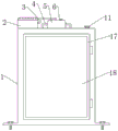
FIG. 2 is a schematic front view of an electrical switchgear with a fire protection system according to the present invention;
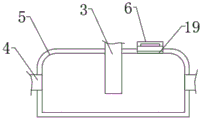
fig. 3 is a schematic elevation view of a vertical section of a fire box of an electrical switchgear with a fire protection system according to the present invention.
In the figure: 1. a cabinet body; 2. an air pump; 3. a breather pipe; 4. a nozzle; 5. a fire extinguishing box; 6. a box plug; 7. an upper switch contact; 8. a return spring; 9. placing the pipe hole; 10. a spray head; 11. a buzzer; 12. a support plate; 13. a switch contact is arranged at the lower part; 14. paraffin wax; 15. a bolt; 16. mounting a plate; 17. a cabinet door; 18. a glass door; 19. and (5) adding powder.
Detailed Description
The technical solutions in the embodiments of the present invention will be clearly and completely described below with reference to the drawings in the embodiments of the present invention, and it is obvious that the described embodiments are only a part of the embodiments of the present invention, and not all of the embodiments. All other embodiments, which can be derived by a person skilled in the art from the embodiments given herein without making any creative effort, shall fall within the protection scope of the present invention.
Referring to fig. 1-3, the invention provides an electrical switch cabinet with a fire protection system, comprising a cabinet body 1, wherein an air pump 2 is fixedly arranged on one side of the top end of the cabinet body 1, a fire extinguishing box 5 is fixedly arranged in the middle of the top end of the cabinet body 1, the output end of the air pump 2 is communicated with the middle of the top end of the fire extinguishing box 5 through a vent pipe 3, the middle parts of the two sides of the fire extinguishing box 5 are communicated with a spray pipe 4, two sides of the middle part of the top end of the cabinet body 1 are respectively provided with a pipe placing hole 9, an upper switch contact 7 is fixedly arranged in the middle of the top end of the cabinet body 1, two sides of the middle part of the top end of the cabinet body 1 are respectively fixedly provided with a return spring 8, the bottom end of the return spring 8 is fixedly provided with a support plate 12, a lower switch contact 13, therefore, the fire extinguishing device can not only extinguish fire rapidly, but also carry out fire alarm.
The output end of the spray pipe 4 reaches the cabinet body 1 through the pipe hole 9, and the spray head 10 is fixedly mounted at the output end of the spray pipe 4, so that the dry powder spraying area can be enlarged, and the fire loss can be reduced rapidly.
Paraffin 14 is supported between the upper switch contact 7 and the lower switch contact 13, and the paraffin 14 can be melted when encountering fire, so that the upper switch contact 7 is contacted with the lower switch contact 13 when encountering fire, and the fire extinguishing system works to extinguish fire.
The cabinet body 1 front end middle part is provided with cabinet door 17, and cabinet door 17 middle part is inlayed and is had glass door 18, and cabinet door 17 one side is rotated through one side of hinge and box and is connected, makes things convenient for the staff to overhaul the device like this.
The both sides of the cabinet body 1 bottom all are provided with mounting panel 16, and 16 top middle parts threaded connection of mounting panel has bolt 15, the stable installation of convenient device of design like this.
The working principle is as follows: when the dry powder extinguishing box is used, the support plate 12 is pulled downwards to separate the upper switch contact 7 from the lower switch contact 13, then the paraffin 14 is supported between the upper switch contact 7 and the lower switch contact 13, the upper switch contact 7 and the lower switch contact 13 are kept separated, then dry powder is introduced into the extinguishing box 5 through the powder adding opening 19, and the powder adding opening 19 is blocked by the box plug 6; through setting up paraffin 14, when meetting the conflagration, paraffin 14 can melt when meetting high temperature, and reset spring 8 resets and draws backup pad 12 upward movement, goes up switch contact 7 and lower switch contact 13 contact, and the circuit switch-on back, air pump 2 is to blowing in the fire-extinguishing chamber 5, and the air current blows dry powder and gets into spray tube 4 and spout cabinet body 1 inside by shower nozzle 10, and the dry powder will be extinguished fire, and bee calling organ 11 sends simultaneously and reports an emergency and asks for help or increased vigilance the staff conflagration.
It is noted that, herein, relational terms such as first and second, and the like may be used solely to distinguish one entity or action from another entity or action without necessarily requiring or implying any actual such relationship or order between such entities or actions. Also, the terms "comprises," "comprising," or any other variation thereof, are intended to cover a non-exclusive inclusion, such that a process, method, article, or apparatus that comprises a list of elements does not include only those elements but may include other elements not expressly listed or inherent to such process, method, article, or apparatus.
Although embodiments of the present invention have been shown and described, it will be appreciated by those skilled in the art that changes, modifications, substitutions and alterations can be made in these embodiments without departing from the principles and spirit of the invention, the scope of which is defined in the appended claims and their equivalents.
Claims (6)
1. An electrical switchgear with fire protection system, comprising a cabinet body (1), characterized in that: the utility model discloses a fire extinguishing cabinet, including the cabinet body, switch contact (7) on the top middle part fixed mounting of the cabinet body (1) top one side fixed mounting have air pump (2), the cabinet body (1) top middle part fixed mounting fire extinguishing box (5), air pump (2) output and fire extinguishing box (5) top middle part are through breather pipe (3) through connection, fire extinguishing box (5) both sides middle part all through connection spray tube (4), the both sides at the cabinet body (1) top middle part have all been seted up and have been put tube hole (9), switch contact (7) on the top middle part fixed mounting of the cabinet body (1) inside, the equal fixed mounting in top middle part both sides of the cabinet body (1) inside has reset spring (8), reset spring (8) bottom fixed mounting has backup pad (12), backup pad (12) top middle part fixed mounting has lower switch contact (13), the cabinet body (1), The upper switch contact (7), the lower switch contact (13) and the buzzer (11) are connected through conducting wires.
2. An electrical switchgear with fire protection system according to claim 1, characterized in that: the output end of the spray pipe (4) reaches the cabinet body (1) through the pipe arranging hole (9), and the output end of the spray pipe (4) is fixedly provided with a spray head (10).
3. An electrical switchgear with fire protection system according to claim 2, characterized in that: and paraffin (14) is supported between the upper switch contact (7) and the lower switch contact (13).
4. An electrical switchgear with fire protection system according to claim 3, characterized in that: powder adding openings (19) are formed in one side of the top end of the fire extinguishing box (5), and box plugs (6) are detachably inlaid in the powder adding openings (19).
5. An electrical switchgear with fire protection system according to claim 4, characterized in that: the improved refrigerator is characterized in that a cabinet door (17) is arranged in the middle of the front end of the cabinet body (1), a glass door (18) is embedded in the middle of the cabinet door (17), and one side of the cabinet door (17) is rotatably connected with one side of the cabinet body through a hinge.
6. An electrical switchgear with fire protection system according to claim 5, characterized in that: the cabinet body (1) both sides of bottom all are provided with mounting panel (16), mounting panel (16) top middle part threaded connection has bolt (15).
Priority Applications (1)
| Application Number | Priority Date | Filing Date | Title |
|---|---|---|---|
| CN202011235038.9A CN112582893A (en) | 2020-11-08 | 2020-11-08 | Electrical switch cabinet with fire protection system |
Applications Claiming Priority (1)
| Application Number | Priority Date | Filing Date | Title |
|---|---|---|---|
| CN202011235038.9A CN112582893A (en) | 2020-11-08 | 2020-11-08 | Electrical switch cabinet with fire protection system |
Publications (1)
| Publication Number | Publication Date |
|---|---|
| CN112582893A true CN112582893A (en) | 2021-03-30 |
Family
ID=75120254
Family Applications (1)
| Application Number | Title | Priority Date | Filing Date |
|---|---|---|---|
| CN202011235038.9A Pending CN112582893A (en) | 2020-11-08 | 2020-11-08 | Electrical switch cabinet with fire protection system |
Country Status (1)
| Country | Link |
|---|---|
| CN (1) | CN112582893A (en) |
Cited By (3)
| Publication number | Priority date | Publication date | Assignee | Title |
|---|---|---|---|---|
| CN113054545A (en) * | 2021-04-13 | 2021-06-29 | 二工防爆科技股份有限公司 | Anti-collision anti-explosion distribution box |
| CN115831682A (en) * | 2022-11-30 | 2023-03-21 | 波普电气有限公司 | Miniature circuit breaker for overload and short-circuit protection |
| CN116759991A (en) * | 2023-08-21 | 2023-09-15 | 交口县光煜光伏发电有限责任公司 | Photovoltaic combiner box alarm and trip protection function device |
-
2020
- 2020-11-08 CN CN202011235038.9A patent/CN112582893A/en active Pending
Cited By (4)
| Publication number | Priority date | Publication date | Assignee | Title |
|---|---|---|---|---|
| CN113054545A (en) * | 2021-04-13 | 2021-06-29 | 二工防爆科技股份有限公司 | Anti-collision anti-explosion distribution box |
| CN115831682A (en) * | 2022-11-30 | 2023-03-21 | 波普电气有限公司 | Miniature circuit breaker for overload and short-circuit protection |
| CN116759991A (en) * | 2023-08-21 | 2023-09-15 | 交口县光煜光伏发电有限责任公司 | Photovoltaic combiner box alarm and trip protection function device |
| CN116759991B (en) * | 2023-08-21 | 2023-10-27 | 交口县光煜光伏发电有限责任公司 | Photovoltaic combiner box alarm and trip protection function device |
Similar Documents
| Publication | Publication Date | Title |
|---|---|---|
| CN210040091U (en) | Fixed circuit breaker | |
| CN106267627B (en) | Transformer explosion fire extinguishing system | |
| CN105790283A (en) | Fireproof ventilation capacitance compensation cabinet | |
| CN108281894B (en) | An internal and external fire alarm and linkage control system for transformer re-ignition fire | |
| CN112803249B (en) | High security switch board | |
| CN212491235U (en) | Comprehensive fire control system of extra-high voltage converter station | |
| CN202506023U (en) | Automatic fire extinguishment box type transformer substation | |
| KR102624477B1 (en) | A control cabinet with self-fire extinguishing function | |
| CN217182707U (en) | Block terminal with intelligence alarming function of putting out a fire | |
| CN206506220U (en) | A kind of all sealed high voltage gas-filling cabinet | |
| CN214100570U (en) | Intelligent high tension switchgear | |
| CN216981171U (en) | Novel fire prevention high temperature resistant switch board | |
| CN208923580U (en) | It is a kind of for fire-fighting can self-extinguishing switchgear | |
| CN207691231U (en) | A kind of low-voltage distribution switch board of included fire-fighting system | |
| CN112271580B (en) | Switch cabinet with fire extinguishing function | |
| CN206211284U (en) | High-voltage switch cabinet with automatic fire extinguishing function | |
| CN210040959U (en) | Low-voltage cabinet | |
| CN208031691U (en) | Switchgear automatic fire extinguisher | |
| CN204767104U (en) | Automatic security against fire switch board | |
| CN210378818U (en) | Arc control device reaches load switch device including arc control device | |
| CN217590303U (en) | Circuit power supply device with line protection function | |
| CN206059955U (en) | A kind of distribution box with preventer | |
| CN209137816U (en) | A kind of fire-proof type substation | |
| CN220253828U (en) | Switch board with electric leakage monitoring function | |
| CN214227603U (en) | Box-type fixed alternating-current metal-enclosed switchgear with monitoring mechanism |
Legal Events
| Date | Code | Title | Description |
|---|---|---|---|
| PB01 | Publication | ||
| PB01 | Publication | ||
| WD01 | Invention patent application deemed withdrawn after publication |
Application publication date: 20210330 |
|
| WD01 | Invention patent application deemed withdrawn after publication |