Disclosure of Invention
The technical problem to be solved by the embodiments of the present invention is to provide a floating cap screwing assembly and a multi-head cap screwing mechanism, so as to perform multi-head synchronous operation.
In order to solve the technical problem, the embodiment of the invention provides a floating spiral cover assembly, which comprises a driving tube, a floating shaft, a front cover and a first spring, wherein the front cover is covered at the front end of the driving tube; one end of the second spring acts on the floating shaft, and the other end acts on the glass beads, so that the glass beads are embedded into the through holes and abut against the inner wall of the driving pipe; a plurality of clamping grooves corresponding to the glass beads are concavely arranged on the inner wall of the driving pipe; one end of the first spring acts on the driving pipe, and the other end of the first spring acts on the clutch ring to push the floating shaft to the front end.
Further, there are 4 groups of through holes, second springs and glass beads.
Correspondingly, the embodiment of the invention also provides a multi-head cap screwing mechanism which comprises the floating cap screwing assembly and a transmission case, wherein one end of the transmission case is provided with a driving motor, the other end of the transmission case is provided with a plurality of groups of driving shafts, a gear transmission pair is arranged in the transmission case, and the driving motor drives the driving shafts to synchronously rotate through the gear transmission pair; the drive shaft is hollow inside, the front end of the drive shaft is provided with a floating cap screwing assembly, and the tail end of a drive pipe of the floating cap screwing assembly is sleeved on the front end of the drive shaft.
The rotary table further comprises a rotary frame, a rotary shaft, a rotary plate and a rotary driving assembly, wherein the rotary shaft is arranged on the rotary frame in a penetrating mode through a bearing, the rotary plate is arranged on the rotary shaft, a press-in air cylinder is arranged on the rotary plate, and the floating rotary cover assembly is arranged on a piston rod of the press-in air cylinder; the rotary driving assembly comprises a gear, a rack and a driving cylinder, the gear is arranged on the rotary shaft, and the rack is meshed with the gear; the piston rod of the driving cylinder is connected with the rack, and the gear is driven to rotate through the driving rack, so that the floating rotary cover assembly on the rotary plate rotates.
Furthermore, the rack-type solar water heater also comprises a guide groove matched with the rack, the rack is arranged in the guide groove, and the rack and the guide groove are both in an inverted T shape.
Furthermore, the rotating plate is provided with a guide rail parallel to the pushing direction of the pressing-in cylinder, the guide rail is provided with a guide block, and the guide block is connected with the bottom of the transmission case of the floating screw cap assembly.
The invention has the beneficial effects that: the invention can be used for quickly changing the model and is compatible with the spinning package of various special-shaped covers, can be used horizontally/vertically, improves the working efficiency of equipment, reduces the equipment cost, reduces the occupied space of the equipment, has strong universality and can be used as a standard part to be universally used in any internal and external thread spinning/capping mechanical equipment within a compatible size range.
Detailed Description
It should be noted that the embodiments and features of the embodiments in the present application can be combined with each other without conflict, and the present invention is further described in detail with reference to the drawings and specific embodiments.
If directional indications (such as up, down, left, right, front, and rear … …) are provided in the embodiment of the present invention, the directional indications are only used to explain the relative position relationship between the components, the movement, etc. in a specific posture (as shown in the drawing), and if the specific posture is changed, the directional indications are changed accordingly.
In addition, the descriptions related to "first", "second", etc. in the present invention are only used for descriptive purposes and are not to be construed as indicating or implying relative importance or implicitly indicating the number of technical features indicated. Thus, a feature defined as "first" or "second" may explicitly or implicitly include at least one such feature.
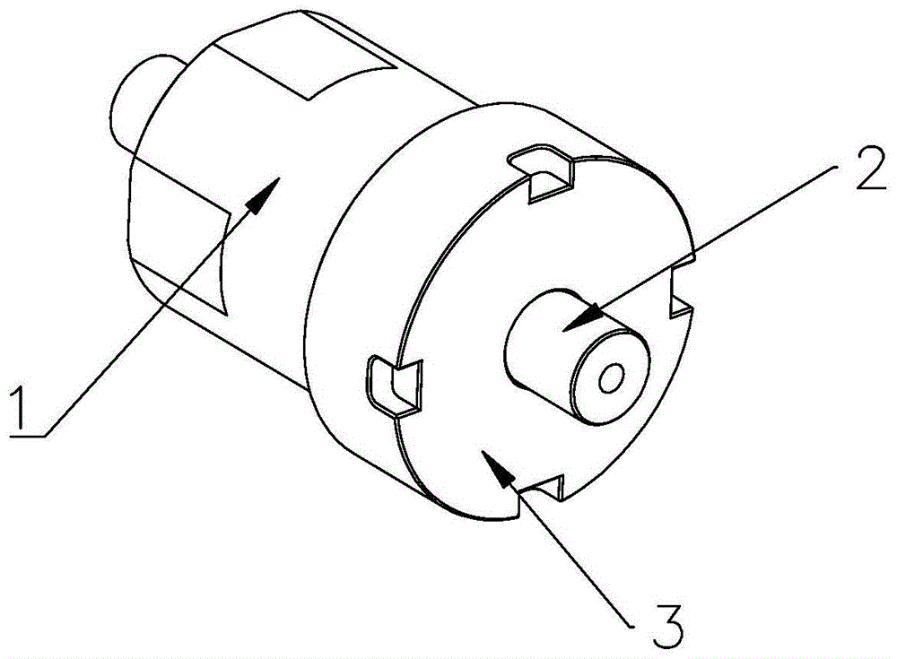
Referring to fig. 1 to 3, a floating cap screwing assembly 10 according to an embodiment of the present invention includes a driving tube 1, a floating shaft 2, a front cap 3, and a first spring 7.
The front end of the driving tube 1 is covered by the front cover 3, the floating shaft 2 penetrates through the driving tube 1 and the front cover 3, the floating shaft 2 is hollow, the periphery of the floating shaft 2 is provided with a clutch ring 4, and the clutch ring 4 is fixed on the floating shaft 2 through a plurality of pins 8. The periphery of the clutch ring 4 is provided with a through hole, and a second spring 5 and a glass bead 6 with the diameter larger than that of the through hole are arranged in the clutch ring 4. The bead 6 is preferably made of steel. One end of the second spring 5 acts on the floating shaft 2, and the other end acts on the glass bead 6, so that the glass bead 6 is embedded into the through hole and abuts against the inner wall of the driving tube 1. The inner wall of the driving tube 1 is concavely provided with a plurality of clamping grooves corresponding to the glass beads 6. Preferably, the slots are equiangularly spaced. One end of the first spring 7 acts on the driving pipe 1, and the other end acts on the clutch ring 4 to push the floating shaft 2 to the front end.
In one embodiment, there are 4 sets of through holes, second spring 5 and beads 6, and the 4 sets of through holes are spaced 90 degrees apart.
As an implementation mode, the inner side of the section of the tail end of the driving pipe 1 is a regular polygon, so that the driving pipe is convenient to disassemble quickly and can prevent sliding when rotating.
When in use, the floating screw cap assembly 10 of the embodiment of the invention can be directly arranged on the driving shaft 13, and the front end of the floating shaft 2 is provided with a profiling cavity or a jig with the profiling cavity is directly arranged. After a material cover (such as a sealing cover of a small paste body or a container such as shoe polish, toothpaste and the like) enters the profiling cavity, vacuum adsorption is carried out through the hollow inside of the floating shaft 2 (the other end of the floating shaft 2 is connected with an air pipe through a rotary joint), and then the material can be fixed.
Referring to fig. 1 to 8, the multi-head cap screwing mechanism according to the embodiment of the present invention includes a floating cap screwing assembly 10 and a transmission case 11. One end of the transmission case 11 is provided with a driving motor 12, the other end is provided with a plurality of groups of driving shafts 13, a gear transmission pair 14 is arranged in the transmission case 11, and the driving motor 12 drives the driving shafts 13 to synchronously rotate in the same direction through the gear transmission pair 14; the driving shaft 13 is hollow, the front end of the driving shaft 13 is provided with a floating cap screwing component 10, and the tail end of the driving pipe 1 of the floating cap screwing component 10 is sleeved on the front end of the driving shaft 13.
The multi-head cap screwing mechanism provided by the embodiment of the invention can be directly used as a vertical cap screwing mechanism. When the floating screw cap assembly 10 at the front end of each driving shaft 13 coincides with the center of the material cap opening, the first spring 7 in the floating screw cap assembly 10 can axially and adaptively stretch out and draw back after hard contact, so that the profiling cavity and the material cap can be conveniently butted. In specific production, the extending lengths of all the material covers in the jig are not absolutely consistent, and the embodiment of the invention can prevent idle rotation caused by non-contact of the cover and the profiling cavity when the cover is screwed by properly pre-pressing the first spring 7.
The driving motor 12 is a stepping motor, and when the driving motor 12 is oriented to start rotating, the driving shafts 13 are driven to rotate in the same direction through the gear transmission pair 14 in the transmission case 11. Because the extension length and the angle of the product in the material are not consistent, the floating cap screwing component 10 finishes screwing the cap in sequence during cap screwing, and the force of the cap screwed first must be removed immediately after the torque of the cap is saturated to enable the corresponding spindle to idle, otherwise the product can be damaged. When the torque is in place, the driving tube 1 of the floating cap screwing component 10 still rotates, the glass bead 6 rotates out from the clamping groove, the glass bead 6 is pressed into the clutch ring 4, and the floating shaft 2 can automatically release force and stop.
The embodiment of the invention can be suitable for sealing various miniature and small pastes with small screwing force and high screwing speed and other containers with internal and external threads with calibers (phi 3-25 mm). For example, shoe polish, toothpaste, syringes and the like can finish the sealing and packaging of a plurality of products at one time by screwing a cover and a gland with threads.
As an implementation mode, the multi-head cap screwing mechanism further comprises a vacuum pressure gauge for detecting vacuum pressure in the floating shaft 2, when the material and the material cap are screwed tightly and completely leave the profiling cavity, the pressure value can be changed, if the spinning is unsuccessful, the material cap can be sucked back to the profiling cavity in a vacuum mode, and the cap screwing success can be guaranteed.
As an implementation mode, the multi-head cap screwing mechanism further comprises a rotating frame 15, a rotating shaft 16, a rotating plate 17 and a rotation driving assembly, wherein the rotating shaft 16 is arranged on the rotating frame 15 in a penetrating manner through a bearing, the rotating plate 17 is arranged on the rotating shaft 16, a press-in air cylinder 18 is arranged on the rotating plate 17, and the floating cap screwing assembly 10 is arranged on a piston rod of the press-in air cylinder 18; the rotary driving assembly comprises a gear 19, a rack 20 and a driving cylinder 21, wherein the gear 19 is arranged on the rotating shaft 16, and the rack 20 is meshed with the gear 19. The piston rod of the driving cylinder 21 is connected with the rack 20, and the rack 20 is driven to drive the gear 19 to rotate, so that the floating rotary cover assembly 10 on the rotary plate 17 rotates. The pressing-in air cylinder 18 drives the floating cap screwing assembly 10 to perform the cap pressing and cap withdrawing actions.
The multi-head cap screwing mechanism provided by the embodiment of the invention can be directly used as a horizontal cap screwing mechanism. The driving cylinder 21 drives the rotating plate 17 to rotate 90 degrees, so that the multi-head cap screwing mechanism is erected, the front port of the floating shaft 2 faces upwards, and the profiling cavity on the floating shaft 2 is used for receiving a single material cap separated from the vibrating disc trough; if the material cover is a special-shaped cover, the driving motor 12 can uniformly adjust the rotation angles of all the floating shafts 2 to enable the rotation angles to be overlapped with the positioning entry points of the special-shaped cover to be blanked, and the material receiving is ensured to be in place.
Preferably, there are two sets of the rotating frame 15, the rotating shaft 16 and the rotating driving assembly, which are respectively disposed on two sides, and two ends of the rotating plate 17 are respectively disposed on the rotating shafts 16 on two sides, so as to improve the stability of the whole.
As an implementation mode, the multi-head cap screwing mechanism further comprises a guide groove 22 matched with the rack 20, the rack 20 is arranged in the guide groove 22, and the rack 20 and the guide groove 22 are both inverted T-shaped.
In one embodiment, the rotating plate 17 is provided with a guide rail 23 parallel to the pushing direction of the pressing cylinder 18, the guide rail 23 is provided with a guide block 24, and the guide block 24 is connected with the bottom of the transmission case 11 of the floating screw cap assembly 10.
Preferably, there are 2 guide rails 23, which are respectively disposed at both sides of the pressing cylinder 18 to improve stability.
The rotary driving assembly adopted by the embodiment of the invention ensures that the gravity center of the integral multi-head cap screwing mechanism is more stable during rotation and the production efficiency is better.
Although embodiments of the present invention have been shown and described, it will be appreciated by those skilled in the art that changes, modifications, substitutions and alterations can be made in these embodiments without departing from the principles and spirit of the invention, the scope of which is defined in the appended claims and their equivalents.