CN112571111A - Clamping device of case cover for automobile - Google Patents
Clamping device of case cover for automobile Download PDFInfo
- Publication number
- CN112571111A CN112571111A CN202011478873.5A CN202011478873A CN112571111A CN 112571111 A CN112571111 A CN 112571111A CN 202011478873 A CN202011478873 A CN 202011478873A CN 112571111 A CN112571111 A CN 112571111A
- Authority
- CN
- China
- Prior art keywords
- pin
- auxiliary
- base
- pressing device
- automobile
- Prior art date
- Legal status (The legal status is an assumption and is not a legal conclusion. Google has not performed a legal analysis and makes no representation as to the accuracy of the status listed.)
- Withdrawn
Links
- 238000003825 pressing Methods 0.000 claims abstract description 41
- 230000007246 mechanism Effects 0.000 description 11
- 238000003754 machining Methods 0.000 description 6
- 238000004519 manufacturing process Methods 0.000 description 5
- 238000012545 processing Methods 0.000 description 3
- 230000009286 beneficial effect Effects 0.000 description 2
- 230000005540 biological transmission Effects 0.000 description 2
- 238000005516 engineering process Methods 0.000 description 2
- 230000006872 improvement Effects 0.000 description 2
- 238000000034 method Methods 0.000 description 2
- 230000004048 modification Effects 0.000 description 2
- 238000012986 modification Methods 0.000 description 2
- 238000005266 casting Methods 0.000 description 1
- 238000005520 cutting process Methods 0.000 description 1
- 230000007547 defect Effects 0.000 description 1
- 238000013461 design Methods 0.000 description 1
- 238000001514 detection method Methods 0.000 description 1
- 238000011161 development Methods 0.000 description 1
- 230000008569 process Effects 0.000 description 1
- 230000009467 reduction Effects 0.000 description 1
- 238000003466 welding Methods 0.000 description 1
Images


Classifications
-
- B—PERFORMING OPERATIONS; TRANSPORTING
- B23—MACHINE TOOLS; METAL-WORKING NOT OTHERWISE PROVIDED FOR
- B23Q—DETAILS, COMPONENTS, OR ACCESSORIES FOR MACHINE TOOLS, e.g. ARRANGEMENTS FOR COPYING OR CONTROLLING; MACHINE TOOLS IN GENERAL CHARACTERISED BY THE CONSTRUCTION OF PARTICULAR DETAILS OR COMPONENTS; COMBINATIONS OR ASSOCIATIONS OF METAL-WORKING MACHINES, NOT DIRECTED TO A PARTICULAR RESULT
- B23Q3/00—Devices holding, supporting, or positioning work or tools, of a kind normally removable from the machine
- B23Q3/02—Devices holding, supporting, or positioning work or tools, of a kind normally removable from the machine for mounting on a work-table, tool-slide, or analogous part
- B23Q3/06—Work-clamping means
- B23Q3/062—Work-clamping means adapted for holding workpieces having a special form or being made from a special material
Landscapes
- Engineering & Computer Science (AREA)
- Mechanical Engineering (AREA)
- Jigs For Machine Tools (AREA)
Abstract
The invention discloses a clamping device of a box cover for an automobile, which comprises a pressing device, wherein the pressing device is fixed on a clamp base and also comprises: the main positioning device comprises a base ring, a large conical pin and a small conical pin, wherein the base ring is fixed on the clamp base, the large conical pin and the small conical pin are arranged on the base ring, the large conical pin is a main positioning pin and limits 2 degrees of freedom, and the small conical pin is an angular positioning pin and limits 1 degree of freedom; and the auxiliary positioning device comprises three support nails which are not on the same straight line, and the top surfaces of the three support nails are positioned on the same plane to limit 3 degrees of freedom. The invention can effectively solve the problems of manual alignment, repeated clamping, low efficiency and unstable quality of the automobile box cover.
Description
Technical Field
The invention relates to the technical field of manufacturing of machine tool technological equipment, in particular to a clamping device for an automobile box cover.
Background
With the rapid development of the automobile industry, automobile parts have the characteristics of large batch and high precision, and have the characteristic of intense processing competition. Automobile part manufacturers have the core competitiveness of enterprises for living in competition for waves, increasing production efficiency, improving machining precision and reducing machining cost. A cover for an automobile, which is an automobile part, must be highly accurate and inexpensive. In actual production, the original clamping device adopts manual alignment and multiple clamping, so that the efficiency is low and the quality is unstable.
Publication (bulletin) No.: CN106239403A, publication (public notice) day: 2016-12-21 discloses an automobile part clamping fixture, which comprises a base, wherein a vertical rail is fixedly arranged on the base, a clamping platform is arranged on the vertical rail in a sliding manner, a driving motor and a clamping rail are arranged on the clamping platform, and the driving motor is connected to the vertical rail in a transmission manner; the clamping rails are provided with clamping plates which are symmetrically arranged at two sides in a sliding manner, and the left ends of the clamping plates are provided with driving motors which are connected to the clamping rails in a transmission manner; the right end of the clamping plate is provided with a through hole and is slidably provided with a guide rod, one end of the guide rod is connected to the clamping plate through a tension spring, and the other end of the guide rod is provided with a V-shaped fixed clamping plate. The invention has reasonable and ingenious structural design and convenient manufacture and use, adopts an electric control clamping mechanism, has stable and quick clamping, greatly improves the production efficiency of products and reduces the labor intensity.
Publication (bulletin) No.: CN110860839A, publication (public notice) day: 2020-03-06 discloses an automobile fixture positioning device, which comprises automobile parts, a base, a first base, a second base, supporting blocks, elastic pressing sheets, a mounting plate and elastic pieces, wherein the first base and the second base are respectively installed on the left side and the right side of the base, the supporting blocks are L-shaped and are respectively and symmetrically arranged on the side walls of the first base and the second base, the mounting plate is fixed on the supporting blocks, grooves for containing the automobile parts are formed in the mounting plate, at least one group of elastic pieces for compressing the automobile parts are arranged in the grooves, pressing columns and the elastic pressing sheets are arranged at the upper ends of the supporting blocks, one ends of the elastic pressing sheets are fixed below the pressing columns, and the other ends of the elastic pressing sheets are. According to the automobile accessory clamp, the automobile accessories are placed on the mounting plate, the automobile accessories can be clamped through the elastic piece on the mounting plate, meanwhile, the elastic pressing piece at the upper end of the supporting block can be used for tightly pressing and fixing the automobile accessories with different sizes and models, and the fixing stability is further improved.
Publication (bulletin) No.: CN108312088B, publication (public notice) day: 2019-12-03 discloses an automobile accessory clamping device which comprises a base and a lifting plate, wherein two sides of the base are symmetrically connected with two guide rods, driven parts in opposite positions and top clamping devices in opposite positions are arranged at the upper parts of the two guide rods, and the top clamping devices are positioned below the driven parts; the lifting plate is vertically and slidably connected to the two guide rods, and a power device for driving the lifting plate to vertically slide is arranged on the base; the middle part of lifter plate is equipped with the seat that bears that is used for bearing auto-parts, and the both sides of lifter plate all are equipped with side clamping device and driving piece symmetrically. The invention aims to provide an automobile accessory clamping device capable of firmly and stably clamping automobile parts.
Publication (bulletin) No.: CN108253861A, publication (public notice) day: 2018-07-06 discloses an automobile part detection tool clamp, which comprises a bottom plate, a lifting mechanism arranged on the bottom plate and used for placing a part to be detected, and a clamping mechanism arranged on the bottom plate and used for clamping the part to be detected. The lifting mechanism comprises a first lifting mechanism for lifting a part to be detected and a plurality of second lifting mechanisms surrounding the first lifting mechanism and used for lifting the part to be detected, and the clamping mechanisms comprise first clamping mechanisms used for carrying out surface positioning on the part to be detected, second clamping mechanisms used for carrying out hole positioning on the part to be detected and third clamping mechanisms used for carrying out surface positioning and hole positioning on the part to be detected.
The technical scheme of the disclosed technology, the technical problems to be solved and the beneficial effects are all different from the technical scheme of the invention, or the technical field or the application occasion is different, and no technical inspiration exists in the technical scheme disclosed above.
Disclosure of Invention
The invention aims to provide a clamping device for an automobile box cover, aiming at overcoming the defects in the prior art, and effectively solving the problems of low efficiency and unstable quality caused by manual alignment and repeated clamping of the automobile box cover.
In order to achieve the purpose, the invention adopts the following technical scheme:
the utility model provides a clamping device of case lid for car, includes closing device, closing device fixes on the anchor clamps base, still includes:
the main positioning device comprises a base ring, a large conical pin and a small conical pin, wherein the base ring is fixed on the clamp base, the large conical pin and the small conical pin are arranged on the base ring, the large conical pin is a main positioning pin and limits 2 degrees of freedom, and the small conical pin is an angular positioning pin and limits 1 degree of freedom;
and the auxiliary positioning device comprises three support nails which are not on the same straight line, and the top surfaces of the three support nails are positioned on the same plane to limit 3 degrees of freedom.
Further, still include:
and the auxiliary supporting devices are provided with five.
Further, the auxiliary supporting device includes:
the auxiliary base is fixed on the clamp base and provided with a longitudinal hole and a transverse wire hole which are communicated;
the spring is arranged in the longitudinal hole;
the support pin is also arranged in the longitudinal hole, the lower end of the support pin is propped against the upper end of the spring, and the upper end of the support pin is exposed out of the longitudinal hole;
and the locking screw is arranged in the transverse screw hole, and the inner end of the locking screw abuts against the side wall of the supporting pin.
Furthermore, the pressing device comprises a main pressing device and an auxiliary pressing device, wherein the main pressing device is a longitudinal pressing device, and the auxiliary pressing device is a transverse pressing device.
Compared with the prior art, the invention has the following beneficial effects:
because the main positioning device adopts one surface and one cylindrical pin point for positioning, and the auxiliary positioning device adopts one pin point for positioning (angular positioning), the quick positioning and the reliable positioning can be realized, and the manual alignment is not needed, thereby realizing the improvement of the efficiency and the reduction of the cost. Meanwhile, 5 auxiliary supports are arranged, the spring supporting pins are always in contact with the parts, the locking screws are locked after the parts are completely clamped, and the supporting pins are always in contact with the parts without damaging the positioning condition in the machining process to play a supporting role, so that the parts are not deformed during machining, and the flatness is stabilized within 0.05 after machining.
Drawings
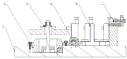
FIG. 1 is a schematic structural view of a clamping device for a cover of an automobile;
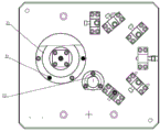
FIG. 2 is a top view of FIG. 1;
FIG. 3 is a view showing a state of use of a clamping device for a cover of an automobile according to the present invention;
FIG. 4 is a top view of FIG. 3;
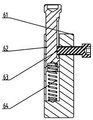
fig. 5 is a main sectional structure view of the auxiliary supporting device.
FIG. 6 is a schematic view of a positioning device.
In the figure: 1, a clamp base; 2, a main positioning device; 3, a main pressing device; 4 auxiliary positioning device; 6 auxiliary supporting device; 7, assisting a pressing device;
21 a primary locating pin; 22 positioning nails; 23 angular positioning pin
61 auxiliary base; 62 support pins; 63 locking screws; 64 springs.
Detailed Description
The technical solutions in the embodiments of the present invention will be clearly and completely described below with reference to the drawings in the embodiments of the present invention, and it is obvious that the described embodiments are only a part of the embodiments of the present invention, and not all of the embodiments. All other embodiments, which can be derived by a person skilled in the art from the embodiments given herein without making any creative effort, shall fall within the protection scope of the present invention.
Referring to fig. 1 to 6, the present invention provides a technical solution:
the utility model provides a clamping device of case lid for car, includes closing device, closing device fixes on anchor clamps base 1, still includes:
the main positioning device 2 comprises a base ring, a large conical pin and a small conical pin, wherein the base ring is fixed on the clamp base, the large conical pin and the small conical pin are arranged on the base ring, the large conical pin is a main positioning pin and limits 2 degrees of freedom, and the small conical pin is an angular positioning pin and limits 1 degree of freedom;
and the auxiliary positioning device 4 comprises three support nails which are not on the same straight line, and the top surfaces of the three support nails are positioned on the same plane to limit 3 degrees of freedom.
Further, still include:
and the auxiliary supporting devices 6 are provided with five.
Further, the auxiliary supporting device includes:
the auxiliary base 61 is fixed on the clamp base, and is provided with a longitudinal hole and a transverse wire hole which are communicated;
a spring 64 disposed within the longitudinal bore;
a support pin 62, which is also arranged in the longitudinal hole, wherein the lower end of the support pin is against the upper end of the spring, and the upper end of the support pin is exposed out of the longitudinal hole;
and the locking screw 63 is arranged in the transverse screw hole, and the inner end of the locking screw abuts against the side wall of the supporting pin.
Further, the pressing device comprises a main pressing device 3 and an auxiliary pressing device 7, wherein the main pressing device is a longitudinal pressing device, and the auxiliary pressing device is a transverse pressing device.
In one embodiment (see FIG. 3): firstly, positioning an automobile box cover 5 through a main positioning device 2 and an auxiliary positioning device 4; secondly, the workpiece is compressed by the main compressing device 3; thirdly, locking the auxiliary supporting device 6; fourthly, the workpiece is pressed by an auxiliary pressing device 7; and finishing workpiece clamping in four steps.
The main positioning device and the auxiliary positioning device have a six-point positioning principle (positioning is performed by two pins on one surface) (see fig. 6): the three supporting nails 22 of the auxiliary positioning device form a plane and limit 3 degrees of freedom; the large taper pin of the primary positioning device is shown as primary positioning pin 21, defining 2 degrees of freedom; the small taper pin is shown as an angular alignment pin 23 defining 1 degree of freedom. Therefore, the device is processed in the first procedure, the positioning hole is a casting hole, and a large error exists, so that the positioning pin is changed from a cylindrical pin to a conical pin.
The auxiliary supporting device adopted by the invention is provided with 5 positions. In the auxiliary supporting device (see fig. 5), the supporting pin 62 is always in contact with the workpiece in the workpiece mounting process under the support of the spring 64, and the locking screw 63 is locked after the workpiece is clamped and compressed;
one main part and one auxiliary part (one surface and two pins) are positioned, the other main part and the other auxiliary part are clamped, and the auxiliary support is arranged at the position 5 and plays a role in preventing the part from being deformed during machining.
The spring support pin keeps in contact with the part all the time, and the locking screw is locked after the part is completely clamped, so that the auxiliary pin plays a supporting role.
The main pressing device 3 presses the box cover in the longitudinal direction through the structure of the bolt and the pressing plate, and the auxiliary pressing device 7 presses the box cover in the transverse direction through the structure of the bolt and the pressing plate, which are conventional and known in the art, and one pressing plate penetrates through the bolt to press one part, which is clear to those skilled in the art and will not be described in detail.
Due to the adoption of the structure, the flatness is stabilized within 0.05 after processing. And the clamping time is reduced from the original 8 minutes to 3 minutes, the clamping efficiency is improved by 2.6 times, the rigidity of the clamping device is improved, the cutting parameters are correspondingly improved, and the total processing efficiency is improved by 1.5 times.
All parts and parts which are not discussed in the present application and the connection mode of all parts and parts in the present application belong to the known technology in the technical field, and are not described again. Such as welding, threaded connections, etc.
In the present invention, the term "plurality" means two or more unless explicitly defined otherwise. The terms "mounted," "connected," "fixed," and the like are to be construed broadly, and for example, "connected" may be a fixed connection, a removable connection, or an integral connection; "coupled" may be direct or indirect through an intermediary. The specific meanings of the above terms in the present invention can be understood by those skilled in the art according to specific situations.
In the description of the present invention, it is to be understood that the terms "upper", "lower", "left", "right", "front", "rear", and the like indicate orientations or positional relationships based on those shown in the drawings, and are only for convenience of description and simplification of description, but do not indicate or imply that the referred device or unit must have a specific direction, be constructed in a specific orientation, and be operated, and thus, should not be construed as limiting the present invention.
In the description herein, the description of the terms "one embodiment," "some embodiments," "specific embodiments," etc., means that a particular feature, structure, material, or characteristic described in connection with the embodiment or example is included in at least one embodiment or example of the invention. In this specification, the schematic representations of the terms used above do not necessarily refer to the same embodiment or example. Furthermore, the particular features, structures, materials, or characteristics described may be combined in any suitable manner in any one or more embodiments or examples.
The above description is only a preferred embodiment of the present invention and is not intended to limit the present invention, and various modifications and changes may be made by those skilled in the art. Any modification, equivalent replacement, or improvement made within the spirit and principle of the present invention should be included in the protection scope of the present invention.
Claims (4)
Priority Applications (1)
| Application Number | Priority Date | Filing Date | Title |
|---|---|---|---|
| CN202011478873.5A CN112571111A (en) | 2020-12-14 | 2020-12-14 | Clamping device of case cover for automobile |
Applications Claiming Priority (1)
| Application Number | Priority Date | Filing Date | Title |
|---|---|---|---|
| CN202011478873.5A CN112571111A (en) | 2020-12-14 | 2020-12-14 | Clamping device of case cover for automobile |
Publications (1)
| Publication Number | Publication Date |
|---|---|
| CN112571111A true CN112571111A (en) | 2021-03-30 |
Family
ID=75135148
Family Applications (1)
| Application Number | Title | Priority Date | Filing Date |
|---|---|---|---|
| CN202011478873.5A Withdrawn CN112571111A (en) | 2020-12-14 | 2020-12-14 | Clamping device of case cover for automobile |
Country Status (1)
| Country | Link |
|---|---|
| CN (1) | CN112571111A (en) |
Cited By (1)
| Publication number | Priority date | Publication date | Assignee | Title |
|---|---|---|---|---|
| CN113829019A (en) * | 2021-09-22 | 2021-12-24 | 山东众联能创动力科技有限公司 | Automatic controller location frock for assembly line |
Citations (7)
| Publication number | Priority date | Publication date | Assignee | Title |
|---|---|---|---|---|
| CN101879680A (en) * | 2009-05-08 | 2010-11-10 | 广西玉柴机器股份有限公司 | Cylinder cover positioning and clamping device in the process of finish-milling top surface of cylinder cover |
| CN203076922U (en) * | 2012-12-29 | 2013-07-24 | 上海沃迪自动化装备股份有限公司 | Auxiliary supporting device |
| KR101378507B1 (en) * | 2012-12-28 | 2014-03-27 | 천영기공 주식회사 | Jig for coordinate measuring machine |
| CN204235155U (en) * | 2014-09-01 | 2015-04-01 | 牧野机床(中国)有限公司 | A kind of water pump cover fixture |
| CN204438977U (en) * | 2014-08-01 | 2015-07-01 | 南京星乔威泰克汽车零部件有限公司 | A kind of cubing holder device for the main pilot hole of automobile oil pan |
| CN205600351U (en) * | 2016-04-14 | 2016-09-28 | 宁夏博璞智库科技咨询服务有限公司 | Self -adaptation positioning mechanism based on two round pins of one side |
| CN214322574U (en) * | 2020-12-14 | 2021-10-01 | 君泽精密机械(山东)有限公司 | Clamping device of case cover for automobile |
-
2020
- 2020-12-14 CN CN202011478873.5A patent/CN112571111A/en not_active Withdrawn
Patent Citations (7)
| Publication number | Priority date | Publication date | Assignee | Title |
|---|---|---|---|---|
| CN101879680A (en) * | 2009-05-08 | 2010-11-10 | 广西玉柴机器股份有限公司 | Cylinder cover positioning and clamping device in the process of finish-milling top surface of cylinder cover |
| KR101378507B1 (en) * | 2012-12-28 | 2014-03-27 | 천영기공 주식회사 | Jig for coordinate measuring machine |
| CN203076922U (en) * | 2012-12-29 | 2013-07-24 | 上海沃迪自动化装备股份有限公司 | Auxiliary supporting device |
| CN204438977U (en) * | 2014-08-01 | 2015-07-01 | 南京星乔威泰克汽车零部件有限公司 | A kind of cubing holder device for the main pilot hole of automobile oil pan |
| CN204235155U (en) * | 2014-09-01 | 2015-04-01 | 牧野机床(中国)有限公司 | A kind of water pump cover fixture |
| CN205600351U (en) * | 2016-04-14 | 2016-09-28 | 宁夏博璞智库科技咨询服务有限公司 | Self -adaptation positioning mechanism based on two round pins of one side |
| CN214322574U (en) * | 2020-12-14 | 2021-10-01 | 君泽精密机械(山东)有限公司 | Clamping device of case cover for automobile |
Cited By (1)
| Publication number | Priority date | Publication date | Assignee | Title |
|---|---|---|---|---|
| CN113829019A (en) * | 2021-09-22 | 2021-12-24 | 山东众联能创动力科技有限公司 | Automatic controller location frock for assembly line |
Similar Documents
| Publication | Publication Date | Title |
|---|---|---|
| CN201016896Y (en) | Clamping device for milled specimens | |
| CN214322574U (en) | Clamping device of case cover for automobile | |
| CN216151791U (en) | Integrated hydraulic clamp for machining special-shaped frame body workpiece | |
| CN112139726A (en) | Beam main body welding reversible deformation device for front crane and use method thereof | |
| CN112935883B (en) | Clamping device for multi-shaft machining of special-shaped thin-wall sleeve and machining method of clamping device | |
| CN117600873A (en) | A box machining clamping and positioning device | |
| CN216177730U (en) | Welding positioning fixture | |
| CN110911936B (en) | A kind of transformer wiring terminal manufacturing and forming processing equipment | |
| CN219946109U (en) | Movable fixture platform for machining | |
| CN221676294U (en) | Iron frame welding part | |
| CN223734026U (en) | Cutting device for cutting ultra-thick target | |
| CN222696925U (en) | A gantry machining center that is easy to maintain | |
| CN114178859B (en) | A horizontal gantry machining center device | |
| CN221910805U (en) | Milling fixture for clamping special-shaped plates | |
| CN112222868B (en) | Machining center structure and machining center control method | |
| CN218576014U (en) | Lower die positioning fixture | |
| CN222211458U (en) | Non-standard workpiece hole position degree gauge | |
| CN222726072U (en) | Quick positioning device for drilling and tapping plate spring seat | |
| CN221967885U (en) | A clamp for producing automobile height adjustment handle | |
| CN220372280U (en) | A steel structure drilling adjustable clamp device | |
| CN223057492U (en) | A clamping fixture for processing quartz products | |
| CN223889444U (en) | Workpiece clamping device of radial drilling machine | |
| CN222269378U (en) | A workpiece vise for drilling and tapping machine | |
| CN113119000B (en) | Clamping device | |
| CN223802014U (en) | A tooling for machining the side beams of a battery box frame |
Legal Events
| Date | Code | Title | Description |
|---|---|---|---|
| PB01 | Publication | ||
| PB01 | Publication | ||
| SE01 | Entry into force of request for substantive examination | ||
| SE01 | Entry into force of request for substantive examination | ||
| WW01 | Invention patent application withdrawn after publication | ||
| WW01 | Invention patent application withdrawn after publication |
Application publication date: 20210330 |