Go upstairs and go on level road and go integrative shallow
Technical Field
The invention relates to a multifunctional cart, in particular to an integrated cart capable of going upstairs and on a flat road.
Background
With the improvement of industrial level, short-distance transportation of goods is the most in the process of goods transportation, steps or stairs are often needed, common goods transportation trolleys can only be used on a flat road in a running mode, when the goods need to go up the steps or go up and down the stairs, the trolleys need to climb the steps or climb the stairs, but the size and the quality of the goods are often large, the conventional solution is to use a hydraulic lifting machine, a goods elevator, reform a gentle slope and manual transportation, the workload of a porter is greatly increased in a manual transportation mode, the labor intensity of the porter is increased, the porter is possibly hurt when the goods are heavy, compared with the manual transportation mode, the hydraulic lifting machine and the goods elevator are more convenient, the goods can be lifted by the hydraulic rod and the motor, the workload and the labor intensity can be effectively reduced, but hydraulic pressure lifts the installation cost of machine and goods lift more expensive and maintenance cost is high to receive the cost restriction can't accomplish that hydraulic pressure all installs and lifts machine or goods lift in any place, reform transform gentle slope and compare in installation hydraulic pressure lift, goods lift will reduce a lot of costs, but service environment receives the restriction, need reform transform domatic alone to the multilayer step, thereby occupy original stair space, and have certain danger when going upstairs and downstairs.
The existing stair climbing cart is mainly used for climbing stairs through the rotation of three idler wheels relative to one shaft, and for the cart for transporting goods, the traditional stair climbing structure is used to be very strenuous and cause danger due to the fact that the quality and the size are too large, so that the workload and the working strength can be increased, and the potential safety hazard can be increased.
Disclosure of Invention
The invention aims to overcome the defects of the traditional technology and provides the stair climbing and flat road running integrated trolley which can easily realize stair climbing, stair climbing and flat road running.
The aim of the invention is achieved by the following technical measures:
the utility model provides an integrative shallow of going upstairs level road, includes shallow frame, drive arrangement and level road travel device, drive arrangement passes through adapting unit with shallow frame and is connected, level road travel device is connected its characterized in that with shallow frame: the flat road running device comprises a running wheel, a transmission shaft and a transmission gear box, wherein the running wheel comprises a driving running wheel and a driven running wheel, the driving running wheel is connected with the transmission shaft in a matched mode through a transmission part, the transmission shaft is sleeved with a group of upstairs arm devices, the group of upstairs arm devices are symmetrically arranged relative to the transmission gear box, and each upstairs arm device comprises a upstairs arm rod assembly and a clutch control assembly.
As an improvement: the arm lever subassembly of going upstairs is the arc arm lever of going upstairs, arc arm lever one end of going upstairs is connected with the arm lever gyro wheel, the arm lever gyro wheel is rubber arm lever gyro wheel, the arc arm lever other end of going upstairs is connected with the linkage axle sleeve.
As an improvement: the clutch control assembly comprises a clutch shifting fork, one end of the clutch shifting fork is connected with a separation shaft sleeve, the other end of the shifting fork is connected with a shifting fork control component, a telescopic rod hole and two limiting rod holes are formed in the clutch shifting fork, and the two limiting rod holes are symmetrically arranged relative to the telescopic rod hole.
As an improvement: the separating shaft sleeve is characterized in that a sliding lug is arranged at one end of the separating shaft sleeve, a separating lug is arranged at the other end of the separating bearing, the separating lug and the sliding lug are arranged oppositely, the sliding lug is connected with the linkage shaft sleeve in a matched mode, one side of the separating lug is connected with the transmission shaft sleeve, a shifting fork groove is formed in the separating shaft sleeve, and the separating shaft sleeve is connected with a separating shifting fork through the shifting fork groove.
As an improvement: the transmission shaft sleeve is connected with the transmission shaft through a connecting part, and the transmission shaft sleeve and the transmission shaft synchronously rotate through the connecting part.
As an improvement: the clutch control assembly comprises a fixed support, a telescopic rod is sleeved on the fixed support, a reset spring is connected onto the telescopic rod, the telescopic rod is connected with the clutch shifting fork, a limiting rod is arranged on the fixed support, and a limiting rod through-hole is connected with the clutch shifting piece.
As an improvement: the rear of the telescopic rod is connected with a control assembly, and the control assembly is installed on the trolley frame.
As an improvement: the transmission shaft comprises two transmission semi-axles and transmission semi-axis coupling assembling, two transmission semi-axles are a set of setting, two transmission semi-axles pass through the cooperation of transmission semi-axis coupling assembling and connect.
Due to the adoption of the technical scheme, compared with the prior art, the invention has the advantages that:
the motor controls the wheels to rotate to drive the cart to run, when the cart needs to go upstairs or upstairs, the motor controls the wheels to rotate and simultaneously drives the upstairs arm device to synchronously rotate, so that the integrated situation of going upstairs and flat road running is realized, the motor serves as a power source of the cart, the cart can have large bearing capacity, the traditional cart can lead to slow transportation speed due to the weight of goods when carrying the goods, the workload and the working intensity of workers can be increased when carrying the heavy objects, manpower can be reduced under the situation of certain bearing capacity by using the motor, the labor intensity is reduced, the transportation efficiency is improved, the difficult problem that the cart goes upstairs or upstairs when carrying the goods is solved through the upstairs arm device, and under the appropriate environment, the cart can be suitable for solving other mechanical equipment with the same problem.
The invention is further described with reference to the following figures and detailed description.
Drawings
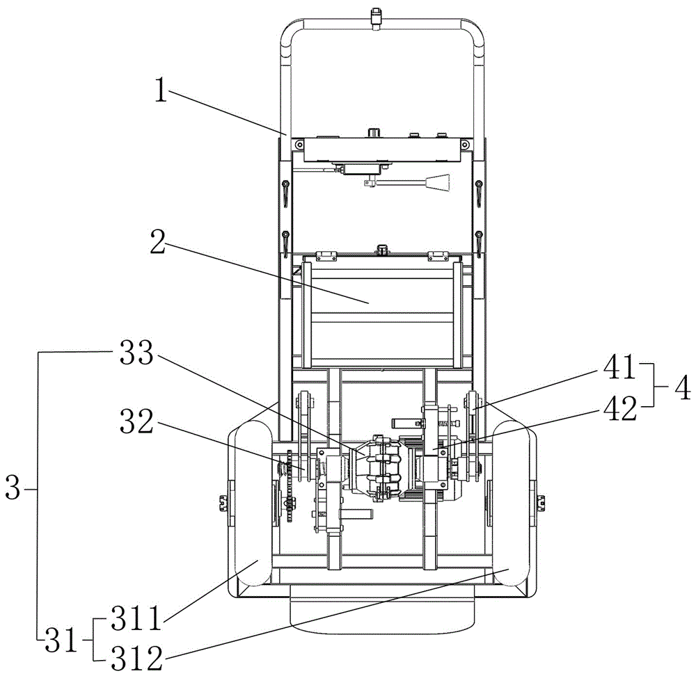
FIG. 1 is a schematic bottom structure of the present invention.
Fig. 2 is a schematic perspective view of the present invention.
Fig. 3 is a schematic perspective view of the flat road running device shown in fig. 2.
Fig. 4 is a schematic view of the structure of the upper arm apparatus of fig. 2.
Fig. 5 is a schematic perspective view of a portion of the arm-climbing device of fig. 4.
Fig. 6 is a side view of a portion of the arm upstairs apparatus of fig. 4.
Fig. 7 is a schematic view of a connection structure of the clutch fork and the release sleeve in fig. 6.
Fig. 8 is a schematic structural view of the clutch fork of fig. 7.
Fig. 9 is a schematic view of the structure of the split bush of fig. 7.
In the figure: 1-a cart frame: 2-driving device: 3-a level road running device: 4-arm device upstairs: 31-running wheel: 32-a transmission shaft: 33-transmission gearbox: 311-driving the running wheels: 312-driven running wheels: 321-transmission half shaft: 322-drive half-shaft coupling assembly: 41-upstairs arm lever assembly: 42-clutch control assembly: 43-clutch fork: 44-separation of the shaft sleeve: 411-arm roller: 412-arc upstairs arm lever: 413-linkage shaft sleeve: 421-fixing support: 422-limiting rod: 423-telescopic rod: 424-driving sleeve: 425-return spring: 431-stop lever hole: 432-telescopic rod hole: 441-separation of bumps: 442-sliding bump: 443-fork groove.
Detailed Description
The technical solutions in the embodiments of the present invention will be clearly and completely described below with reference to the drawings in the embodiments of the present invention, and it is obvious that the described embodiments are only a part of the embodiments of the present invention, and not all of the embodiments. All other embodiments, which can be derived by a person skilled in the art from the embodiments given herein without making any creative effort, shall fall within the protection scope of the present invention.
Example (b): as shown in fig. 1 and 2, an integral cart for going upstairs and on level roads comprises a cart frame 1, a driving device 2 and a level road running device 3, wherein the driving device 2 is connected with the cart frame 1 through a connecting component, the level road running device 3 is connected with the cart frame 1, the level road running device 3 comprises a running wheel 31, a transmission shaft 32 and a transmission gear box 33, the running wheel 31 comprises a driving running wheel 311 and a driven running wheel 312, the driving running wheel 311 is connected with the transmission shaft 32 through a transmission component in a matching manner, a group of upstairs arm devices 4 are sleeved on the transmission shaft 32, the group of upstairs arm devices 4 are symmetrically arranged relative to the transmission gear box 33, and the upstairs arm devices 4 comprise an upstairs arm rod component 41 and a clutch control component 42.
The arm lever assembly 41 is an arc-shaped arm lever 412 for going upstairs, one end of the arc-shaped arm lever 412 for going upstairs is connected with an arm lever roller 411, the arm lever roller 411 is a rubber arm lever roller 411, and the other end of the arc-shaped arm lever 412 for going upstairs is connected with a linkage shaft sleeve 413. The arc-shaped upstairs arm lever 412 with the arc-shaped structure can have stronger rigidity, and the arm lever roller 411 made of rubber can better provide enough friction force when going upstairs or steps.
The clutch control assembly 42 is connected with a clutch fork 43, one end of the clutch fork 43 is connected with a separation shaft sleeve 44, and the other end of the clutch fork 43 is connected with the clutch control assembly 42. The throw-away hub 44 is slidably connected to the drive shaft 32.
The clutch mechanism is characterized in that a sliding protrusion 442 is arranged at one end of the separation shaft sleeve 44, a separation protrusion 441 is arranged at the other end of the separation shaft sleeve 44, the separation protrusion 441 and the sliding protrusion 442 are arranged oppositely, the sliding protrusion 442 is connected with the linkage shaft sleeve 413 in a matched mode, a transmission shaft sleeve 424 is connected to one side of the separation protrusion 441, a shifting fork groove 443 is formed in the separation shaft sleeve 44, and the separation shaft sleeve 44 is connected with a shifting fork of the clutch 43 through the shifting fork groove 443. The sliding protrusion 442 is normally located in the linking shaft sleeve 413, and at this time, the disengagement protrusion 441 is not in contact with the driving shaft sleeve 424, so that the rotation speed of the driving shaft sleeve 424 cannot be transmitted to the linking shaft sleeve 413, when the clutch fork 43 drives the disengagement shaft sleeve 44 to move toward the center, the disengagement protrusion 441 is in fit connection with the driving shaft sleeve 424, and at this time, the sliding protrusion 442 is not disengaged from the linking shaft sleeve 413, so that the disengagement shaft sleeve 44 transmits the rotation speed of the driving shaft sleeve 424 to the linking shaft sleeve 413, thereby enabling the linking shaft sleeve 413 and the driving shaft sleeve 424 to rotate synchronously.
The outdrive 424 is connected to the driveshaft 32 via a coupling element that allows the outdrive 424 to rotate synchronously with the driveshaft 32. The connecting members may be pins or keys, which may reduce the complexity of the manufacturing process of the outdrive 424 and the driveshaft 32, thereby increasing compatibility and reducing cost.
Clutch control assembly 42 includes fixed bolster 421, telescopic link 423 has been cup jointed on the fixed bolster 421, be connected with reset spring 425 on the telescopic link 423, telescopic link 423 is connected with separation and reunion shift fork 43, be equipped with gag lever post 422 on the fixed bolster 421, gag lever post 422 expert closes the gag lever post hole 431 and is connected with the separation and reunion plectrum. When going upstairs and downstairs or going upstairs, the telescopic rod 423 is controlled to move to drive the clutch shifting fork 43, so that the clutch shifting fork 43 drives the clutch shaft sleeve, and when the actions of going upstairs and downstairs or going upstairs are finished, the telescopic rod 423 is stopped to restore to the original state under the action of the return spring 425, so that the clutch shifting fork 43 controls the clutch shaft sleeve to restore to the original state.
The rear of the telescopic rod 423 is connected with a control component, and the control component is installed on the trolley frame 1. The control assembly is installed on a control panel, and the control panel can further comprise functions of controlling the output power of the motor, monitoring the residual electric quantity of the battery, controlling the on-off state of the motor and the like.
The transmission shaft 32 comprises two transmission half shafts 321 and a transmission half shaft connecting assembly 322, the two transmission half shafts 321 are arranged in a group, and the two transmission half shafts 321 are connected in a matching mode through the transmission half shaft connecting assembly 322. The transmission shaft 32 formed by the two transmission half shafts 321 can meet technical requirements during assembly, technical difficulty during assembly is reduced, and the transmission half shaft connecting assembly 322 can be connected in a reliable connecting mode such as a shaft sleeve, a pin or a key.
It will be evident to those skilled in the art that the invention is not limited to the details of the foregoing illustrative embodiments, and that the present invention may be embodied in other specific forms without departing from the spirit or essential attributes thereof. The present embodiments are therefore to be considered in all respects as illustrative and not restrictive, the scope of the invention being indicated by the appended claims rather than by the foregoing description, and all changes which come within the meaning and range of equivalency of the claims are therefore intended to be embraced therein. Any reference sign in a claim should not be construed as limiting the claim concerned.
Furthermore, it should be understood that although the present description refers to embodiments, not every embodiment may contain only a single embodiment, and such description is for clarity only, and those skilled in the art should integrate the description, and the embodiments may be combined as appropriate to form other embodiments understood by those skilled in the art.