CN112525135B - Detection device for intelligent manufacturing - Google Patents
Detection device for intelligent manufacturing Download PDFInfo
- Publication number
- CN112525135B CN112525135B CN202011635133.8A CN202011635133A CN112525135B CN 112525135 B CN112525135 B CN 112525135B CN 202011635133 A CN202011635133 A CN 202011635133A CN 112525135 B CN112525135 B CN 112525135B
- Authority
- CN
- China
- Prior art keywords
- detection
- bearing
- plate
- rod
- gear
- Prior art date
- Legal status (The legal status is an assumption and is not a legal conclusion. Google has not performed a legal analysis and makes no representation as to the accuracy of the status listed.)
- Active
Links
Images

Classifications
-
- G—PHYSICS
- G01—MEASURING; TESTING
- G01B—MEASURING LENGTH, THICKNESS OR SIMILAR LINEAR DIMENSIONS; MEASURING ANGLES; MEASURING AREAS; MEASURING IRREGULARITIES OF SURFACES OR CONTOURS
- G01B21/00—Measuring arrangements or details thereof, where the measuring technique is not covered by the other groups of this subclass, unspecified or not relevant
- G01B21/20—Measuring arrangements or details thereof, where the measuring technique is not covered by the other groups of this subclass, unspecified or not relevant for measuring contours or curvatures, e.g. determining profile
Abstract
The invention provides a detection device for intelligent manufacturing, which can more intuitively display the specific change condition of the cylindricity of a detected bearing piece, is convenient for a worker to further process unqualified parts, and can autonomously change the relative positions of a detection rod relative to the outer circular surface of a bearing outer ring and the inner circular surface of the bearing inner ring according to bearings of different models, so that bearings of any model within a certain model range can be detected, the detection range of the detection device is expanded, and the automation degree is greatly improved.
Description
Technical Field
The invention relates to the technical field of industrial part manufacturing detection, in particular to a detection device for intelligent manufacturing.
Background
In the industrial production process, particularly in the production and processing process of bearing parts, the cylindricity of the bearing parts needs to be detected to ensure the qualification rate of the bearing parts when the bearing parts leave factory, because of the characteristics of the shapes of the bearing parts, the diameters of the outer ring and the inner ring of the bearing of different models need to be changed, the relative position of a detection device needs to be changed when one bearing model is changed, in addition, a factory belongs to assembly line operation when the shaft parts are produced, the number of the bearing parts on the production line is large, therefore, the length of the shaft parts is detected by adopting a manual check mode mostly to evaluate the whole qualification rate of the parts when the parts leave factory, but the precision of the qualification rate of the parts when leaving factory is greatly reduced obviously by adopting the detection mode, and the deviation of the qualification rate of the parts when actually leaving factory is large, so that the whole quality of the parts when leaving factory is influenced;
the manual spot check detection mode is not in line with the fast-paced and high-quality production of modern industrial production at present, and the prior art needs to be improved;
in view of the above, we provide a detection apparatus for smart manufacturing to solve the above problems.
Disclosure of Invention
Aiming at the situation and overcoming the defects of the prior art, the invention provides the detection device for intelligent manufacturing, which can more intuitively display the specific change condition of the cylindricity of the detected bearing piece, is convenient for the workers to further process unqualified parts, and can autonomously change the relative positions of the detection rod relative to the outer circular surface of the outer ring of the bearing and the inner circular surface of the inner ring of the bearing according to bearings of different models, so that bearings of any model within a certain model range can be detected, the detection range of the detection device is expanded, and the automation degree is greatly improved.
The specific technical scheme is as follows:
a detection device for intelligent manufacturing comprises a detection table and is characterized in that a bearing detection device is arranged on the detection table and comprises a bearing plate which is in vertical sliding fit with the detection table, a first fan-shaped helical gear is rotatably arranged on the bearing plate and driven by a detection motor, the detection helical gear and a lifting helical gear which are matched with the first fan-shaped helical gear are rotatably arranged on two transverse sides of the first fan-shaped helical gear, an installation cylinder which is coaxial with the detection helical gear is fixedly arranged at the lower end of the bearing plate, a detection cylinder which is in axial sliding fit with the detection helical gear is arranged in the installation cylinder, a first sliding cylinder is fixedly arranged at the horizontal position of the lower end of the detection cylinder, an inner detection rod is slidably arranged in the first sliding cylinder, a first spring is connected between the inner detection rod and the first sliding cylinder, a connecting plate is rotatably arranged at the upper end of the detection cylinder, and a lifting lead screw which is in coaxial rotation with the lifting helical gear is in threaded fit with the other end of the connecting plate, the lifting helical gear is fixedly sleeved at the upper end of the lifting screw rod, the detection plate vertically matched with the mounting cylinder in a sliding manner is rotatably arranged on the detection cylinder, a second sliding cylinder is arranged on the detection plate, an outer detection rod is arranged in the second sliding cylinder in a sliding way, a second spring is connected between the outer detection rod and the second sliding cylinder, the inner detection rod and the outer detection rod are respectively connected with an inner detection screw rod and an outer detection screw rod which are rotatably arranged on the bearing plate through an amplifying device, the inner detection screw rod and the outer detection screw rod are transversely arranged at intervals, the amplifying device converts the sliding distance between the inner detection rod and the outer detection rod into the rotation angle of the inner detection screw rod and the outer detection screw rod, and amplifies the rotation angle and the equal proportion by a certain multiple, the outer detection screw rod and the inner detection screw rod are both in threaded fit with a mounting plate, and the mounting plate is provided with a recording pen, the bearing plate is provided with a picture scroll matched with the recording pen, and the picture scroll is connected with the detection bevel gear through first belt transmission;
the installation cylinder is provided with a transmission device for detecting the milling stage of the bevel gear, the transmission device can enable the inner detection rod to rotate synchronously with the outer ring of the detected object at the same speed, and the detection table is provided with a positioning and clamping device which can enable the detected object to be centered and clamped.
Preferably, the amplifying device comprises an outer detection toothed column which is rotatably arranged on the bearing plate and is connected with an outer detection lead screw through fourth belt transmission, the outer detection toothed column is matched with an outer detection rack which is in sliding fit with the detection plate, and the outer detection rack is fixedly arranged at one end, away from the mounting cylinder, of the outer detection rod;
the inner detection screw rod is connected with an inner detection gear which is rotatably arranged at the upper end of the bearing plate and coaxially arranged with the detection cylinder through a fifth belt in a transmission manner, and the inner detection gear is meshed with an inner detection rack which is in sliding fit with the detection cylinder and one end of the inner detection rack is fixedly arranged on the inner detection rod and extends out of one end of the second sliding cylinder.
Preferably, rotating device is including setting up the round frame that is located the detection board lowest position downside at the installation cylinder, round frame and installation cylinder set up with the axle center and the round frame internal diameter is greater than the maximum displacement distance of accessory plate, round frame outer disc slidable mounting has terminal surface gear and terminal surface gear meshing to have the rotation driven gear who rotates and install on the round frame, be provided with on the round frame with the coaxial pivoted rotation driven bevel gear of rotating gear and rotate driven bevel gear meshing to have the rotation and install the rotation initiative bevel gear on the round frame, it is connected with the rotation through the sixth belt drive and installs rotation initiative bevel gear and detection bevel gear meshing in the bolster upper end to rotate the initiative bevel gear, fixed mounting has the electro-magnet towards detecting the platform on the terminal surface gear outer disc.
Preferably, an adjusting lead screw is rotatably mounted in the detection plate along the extension direction of the detection plate and driven by an adjusting motor fixedly mounted on the detection plate, the adjusting lead screw is in threaded fit with a moving plate, the moving plate is in sliding fit with the detection plate, a second sliding cylinder is fixedly mounted on one side, facing the mounting cylinder, of the moving plate, an outer detection rack is in sliding fit with the moving plate, and a first electronic telescopic rod fixedly mounted at the tail end of the horizontal part of the detection cylinder drives the first sliding cylinder;
and a fourth electronic telescopic rod and an electromagnet are fixedly arranged on the outer circular surface of the end face gear and are fixedly arranged at the tail end of the fourth electronic telescopic rod.
Preferably, a plurality of auxiliary plates are arranged on the outer circular surface of the mounting cylinder at intervals and driven by a second electronic telescopic rod fixedly mounted on the mounting cylinder, and the sliding fit part of the detection plate and the mounting cylinder is positioned between the two auxiliary plates.
Preferably, one end of the adjusting screw rod positioned in the mounting cylinder is sleeved with an adjusting driven bevel gear which is meshed with an adjusting driving bevel gear rotatably mounted at the upper end of the detection plate, the adjusting driving bevel gear is axially matched with an adjusting gear which is rotatably arranged at the upper end of the bearing plate in a sliding way, the adjusting gear is driven by an adjusting motor which is fixedly arranged at the upper end of the bearing plate, the adjusting motor is driven by a seventh belt to rotate a first marking screw rod arranged on the bearing plate, the bearing plate is provided with a second marking screw rod which is transversely arranged at intervals with the first marking screw rod, the second marking screw rod is driven by a marking motor fixedly mounted on the bearing plate, the first marking screw rod and the second marking screw rod are in threaded fit with a U-shaped frame in vertical sliding fit with the bearing plate, marking pens are arranged on two cantilevers of the two U-shaped frames, and the recording pens are located on two marking pen symmetry lines.
Preferably, it is provided with a leveling cylinder and a leveling cylinder is located axle center department universal connection and has the load pole to examine a platform lower extreme, the interval encircles and is provided with a plurality of response balls and a plurality of response ball and the clearance setting of load pole in the leveling cylinder, examine such as interval rings of outer disc lower extreme of test table and be provided with a plurality of and examine the vertical sliding fit's of test table stabilizer blade and a plurality of stabilizer blade by the third electronic telescopic link drive of fixed mounting on examining the test table.
Preferably, the positioning and clamping device comprises a rotary table which is rotatably arranged in the detection table and coaxially rotates with the detection table, the rotary table is driven by a positioning motor fixedly arranged on the detection table, a plurality of inclined sliding grooves are formed in the rotary table in an interval surrounding manner, positioning blocks are matched in the sliding grooves in a sliding manner, a plurality of straight grooves along the radial direction of the straight grooves are formed in the upper end of the detection table in an interval surrounding manner, and the straight grooves are matched with the positioning blocks in a sliding manner; it transversely keeps away from picture scroll one side rotation and installs the fan-shaped helical gear of second and the fan-shaped helical gear of second by fixed mounting detect the tight motor drive of clamp on the bench to detect bench, it transversely deviates from installation cylinder one side rotation and installs the tight helical gear of clamp and press from both sides tight helical gear through the second belt drive be connected with carousel with axle center pivoted lower clamp lead screw to detect bench to lie in the fan-shaped helical gear of second on the bench, press from both sides tight platform and detect the vertical sliding fit of platform down, it transversely deviates from tight helical gear one side rotation and installs the tight lead screw of clamp and go up the tight lead screw of clamp and be driven by clamp motor through the third belt drive to detect bench to lie in the fan-shaped helical gear of second, go up the tight lead screw of clamp and the bearing board screw-thread fit.
The invention has the beneficial effects that: (1) the invention can more intuitively display the specific change condition of the cylindricity of the detected bearing piece, thereby facilitating the further processing of unqualified parts by workers;
(2) the invention can autonomously change the relative position of the detection rod relative to the outer circular surface of the bearing outer ring and the inner circular surface of the bearing inner ring according to bearings of different models, namely, the invention can detect bearings of any model within a certain model range, thereby enlarging the detection range of the detection device and greatly improving the automation degree;
(3) the invention is also provided with a positioning and clamping device which automatically clamps the bearing and determines the positions of the inner detection rod and the outer detection rod according to the rotation angle of the turntable;
(4) the invention is provided with the leveling device, and the detection platform is in a relatively horizontal state through the leveling device, so that the qualification rate detection is more accurate.
Drawings
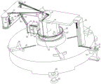
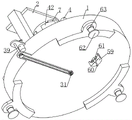
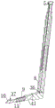
FIG. 1 is an isometric, schematic view of the present invention;
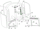
FIG. 2 is a partial schematic view of the present invention at A;
FIG. 3 is a partial schematic view of the invention at B;
FIG. 4 is a schematic view of the driving of the inner and outer detecting rods according to the present invention;
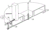
FIG. 5 is a schematic bottom perspective view of the present invention;
FIG. 6 is a schematic view, partially in section, of an assembly of the inspection station of the present invention;
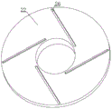
FIG. 7 is a schematic view of the chute arrangement of the present invention;
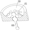
FIG. 8 is a schematic view of the assembly of the leveling cylinder of the present invention;
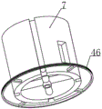
FIG. 9 is a schematic view of the mounting barrel of the present invention;
FIG. 10 is a schematic cross-sectional view of the assembly of the present invention in a test cartridge;
FIG. 11 is a schematic view of the internal assembly of the mounting cylinder of the present invention;
FIG. 12 is a schematic half-section view of a test stand according to the present invention;
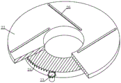
FIG. 13 is a partial schematic view of a turntable according to the present invention;
FIG. 14 is a schematic view illustrating an exemplary detection of a bearing type according to the present invention;
FIG. 15 is a schematic view of the assembly position of the stylus and the marker of the present invention.
Detailed Description
The foregoing and other aspects, features and advantages of the invention will be apparent from the following more particular description of the embodiments of the invention, as illustrated in the accompanying drawings in which reference is made to figures 1 to 15.
Exemplary embodiments of the present invention will be described below with reference to the accompanying drawings.
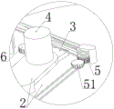
Embodiment 1, this embodiment provides a detection apparatus for intelligent manufacturing, refer to fig. 1, it includes a detection table 1, we have a positioning and clamping device on the detection table 1, we can center the bearing placed on the detection table 1 by the positioning and clamping device, then clamp it, prevent the bearing from shifting and influencing the measurement result in the detection process, we have a bearing detection apparatus on the detection table 1, it includes a bearing plate 2 installed with the detection table 1 in a vertical sliding manner, and a first fan-shaped helical gear 3 installed on the bearing plate 2 in a rotating manner, and the first fan-shaped helical gear 3 is driven by a detection motor 4 and the detection motor 4 is connected with an external power supply, and an electric connection has a first controller, through which the rotation angle and forward and backward rotation of the detection motor 4 can be controlled, refer to fig. 4 in addition, the detection bevel wheel 5 and the lifting bevel wheel 6 which are matched with the first fan-shaped bevel wheel 3 are respectively and rotatably arranged at two transverse sides of the first fan-shaped bevel wheel 3, the lower end of the bearing plate 2 is fixedly provided with an installation cylinder 7 (the structure of the installation cylinder 7 refers to an attached drawing 9) which is coaxially arranged with the detection bevel wheel 5, the installation cylinder 7 is internally provided with a detection cylinder 8 which is axially and slidably matched with the detection bevel wheel 5, namely, when the first fan-shaped bevel wheel 3 is meshed with the detection bevel wheel 5 and drives the detection bevel wheel 5 to rotate, the detection bevel wheel 5 can simultaneously drive the detection cylinder 8 to synchronously rotate, so that a first sliding cylinder 9 is fixedly arranged at the horizontal part at the lower end of the detection cylinder 8, an inner detection rod 10 is slidably arranged in the first sliding cylinder 9, one end of the inner detection rod 10 extending into the first sliding cylinder 9 is fixedly connected with a first spring 11, and the other end of the first spring 11 is connected with the bottom wall of the first sliding cylinder 9, therefore, the inner detection rod 10 is driven to rotate when the detection cylinder 8 rotates, and the roundness of a certain section of the inner circle surface of the bearing inner ring can be detected after the inner detection rod 10 rotates for a circle, in order to detect the roundness of the bearing more accurately, different parts of the bearing in the vertical direction (the bearing is horizontally arranged at the moment, the opening of the bearing is upward) are detected, therefore, a connecting plate 12 is rotatably connected to the upper end of the detection cylinder 8, the connecting plate 12 is intermittently matched with the shaft of the detection bevel gear 5, a lifting screw 13 rotatably installed on the bearing plate 2 is in threaded fit with the other end of the connecting plate 12, the lifting bevel gear 6 is fixedly sleeved on the upper end of the lifting screw 13, and thus when the first sector bevel gear 3 is meshed with the lifting bevel gear 6 and drives the lifting bevel gear 6 to rotate, the lifting screw 13 is driven to rotate by the lifting bevel gear 6, so that the connecting plate, then, the detection cylinder 8 is driven to vertically move, so that different positions of the bearing can be detected, the outer circular surface of the detection cylinder 8 and the lower end of the mounting cylinder 7 can slide and rotate relatively, the connection between the detection cylinder 8 and the mounting cylinder 7 plays a role in stabilizing, and the detection cylinder 8 is prevented from shaking violently during rotation;
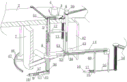
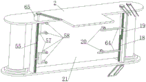
because the bearing is divided into an inner ring and an outer ring, the outer ring is required to be detected when the inner ring is detected, and therefore, referring to the attached drawing 4, a detection plate 14 is rotatably installed on a detection cylinder 8, so that the detection cylinder 8 can be driven to synchronously move when vertically moving, a groove which is vertically matched with the detection plate 14 in a sliding manner is formed in the side wall of a mounting cylinder 7, the vertical height of the groove is the vertical sliding range of the detection plate 14, a second sliding cylinder 15 is arranged on one side of the detection plate 14, which extends out of the mounting cylinder 7, an outer detection rod 16 is in sliding fit in the second sliding cylinder 15, one end of the same outer detection rod 16, which extends into the second sliding cylinder 15, is fixedly connected with a second spring 17, the other end of the second spring 17 is fixedly connected to the bottom wall of the second sliding cylinder 15, and a second sliding cylinder 15 is arranged on the detection plate 14 and the detection plate 14 which are in sliding fit in the vertical direction, an outer detection rod 16 is arranged in the second sliding cylinder 15 in a sliding mode, a second spring 17 is connected between the outer detection rod 16 and the second sliding cylinder 15, a rotating device is arranged on the mounting cylinder 7, the outer ring of the bearing and the rod of the inner detection can synchronously rotate at the same speed through the rotating device, in this way, when the inner detection rod 10 rotates for one circle, the outer ring of the bearing can also rotate for one circle at the same speed through the rotating device, the outer ring of the bearing can be detected even if the outer detection rod does not move, the outer detection rod 16 and the second sliding cylinder 15 are arranged on the detection plate 14, in this way, the outer ring of the bearing can be detected at different positions along with the movement of the detection plate 14, in addition, the rotating shaft center of the inner detection rod 10 and the rotating shaft center of the outer ring of the bearing are arranged to be the same, and then the roundness detection of the inner ring and the outer ring of the bearing can be synchronously detected by taking the inner detection rod as a reference, therefore, the cylindricity of the bearing can be detected, in order to make the detection result more convenient for the examination of the staff, referring to the attached figure 15, we connect the inner detection rod 10 and the outer detection rod 16 with the inner detection screw 18 and the outer detection screw 19 which are rotatably installed on the bearing plate 2 respectively through the amplifying device, and the inner detection screw 18 and the outer detection screw 19 are transversely arranged at intervals, and the amplifying device makes the sliding distance of the inner detection rod 10 and the outer detection rod 16 along the radial direction of the bearing in the first sliding cylinder 9 and the second sliding cylinder 15 respectively convert into the rotating angle of the inner detection screw 18 and the outer detection screw 19 and amplify a certain times in equal proportion, in addition, the outer detection screw 19 and the inner detection screw 18 are both in threaded fit with the mounting plate 64 and the mounting plate 64 is provided with the recording pen 20, we also are provided with the scroll 21 matched with the recording pen 20 on the bearing plate 2, and the scroll 21 is connected with the detection bevel gear 5 through the first belt transmission, then the inner detecting rod 10 will rotate and at the same time will drive the picture scroll 21 to rotate, the picture scroll 21 includes two shafts rotatably matching with the support plate 2, and one shaft is rolled with the picture paper, and one end of the picture paper is connected with the other shaft, so that when this shaft rotates, the picture paper can be rolled and rotated together, so that the picture paper is gradually transferred from one shaft to the other shaft, and because the recording pen 20 is abutted on the picture paper, the recording pen 20 will leave marks on the picture paper when the picture scroll 21 rotates, and the sliding of the inner detecting rod 10 and the outer detecting rod 16 is converted into the vertical movement of the mounting plate 64 through the amplifying device, i.e. the vertical movement of the recording pen 20, so that the recording pen 20 will leave marks of the wave line on the picture paper, and the cylindricity of the bearing can be determined by observing the amplitude of the wave line corresponding to the inner detecting rod 10 and the outer detecting rod 16, in order to avoid the interference of traces left by the recording pen 20 due to vertical movement of the mounting plate 64 corresponding to the inner detection screw 18 and the mounting plate 64 corresponding to the outer detection screw 19 in the detection process, the scroll 21 is divided into an upper part and a lower part, namely, an area which is at the lower end of the outer detection screw 19 when the mounting plate 64 corresponding to the outer detection screw 19 is at the initial position and has a movement range below the center line of the scroll 21, and an area which is at the upper end of the inner detection screw 18 and has a movement range above the center line of the scroll 21 when the mounting plate 64 corresponding to the inner detection screw 18 is at the initial position;
at the initial position, the inner detection rod 10 and the outer detection rod 16 are at the same horizontal position, the first fan-shaped helical gear 3 is positioned between the detection helical gear 5 and the lifting helical gear 6 and is not meshed with each other, the bearing is placed at the corresponding position of the detection table 1 during detection, then the bearing is firstly centered and then clamped through the positioning and clamping device, at the moment, the bearing plate 2 descends under the action of the positioning and clamping device, so that the bottom surface of the mounting cylinder 7 is in close contact with the upper end surface of the inner ring of the bearing, the inner detection rod 10 is in contact with the inner circle surface of the bearing, the outer detection rod 16 is also in contact with the outer circle surface of the outer ring of the bearing, then the first controller starts the motor to rotate clockwise (taking the view angle of the attached drawing 1 as the reference), so that the first fan-shaped helical gear 3 rotates clockwise and is firstly meshed with the detection helical gear 5, then the detection helical gear 5 is driven to rotate anticlockwise, when the first fan-shaped helical gear 3 is disengaged from the detection helical gear 5, the detection bevel gear 5 rotates for a circle, thereby driving the detection cylinder 8 to rotate anticlockwise for a circle, further driving the inner detection rod 10 to rotate anticlockwise for a circle in the inner circle of the bearing inner ring, thereby detecting the roundness of the circle at the position, the bearing outer ring rotates clockwise for a circle under the action of the rotating device, so that the outer detection rod 16 also detects the cylinder of the circle at the position, the two are combined to detect the cylindricity of the position, then the amplification mechanism respectively drives the inner detection lead screw 18 and the outer detection lead screw 19 to rotate, so that the mounting plate 64 in threaded fit with the two also vertically moves along with the rotation, the recording pen 20 also moves along with the rotation, and the scroll 21 is connected with the detection bevel gear 5 through the first belt transmission, so that the scroll 21 is driven to rotate for a circle when the detection bevel gear 5 rotates for a circle, so that the recording pen 20 leaves wave marks on the scroll paper of the scroll 21, in addition, after the first fan-shaped helical gear 3 is separated from the detection helical gear 5, a circle of detection of one position is completed, then the detection motor 4 continues to drive the first fan-shaped helical gear 3 to rotate, so that the first fan-shaped helical gear 3 can be meshed with the lifting helical gear 6 to drive the lifting screw 13 to rotate, so that the connecting plate 12 moves downwards in the mounting cylinder 7 for a certain distance, thus the inner detection rod 10 and the outer detection rod 16 can descend for a certain distance relative to the mounting cylinder 7, when the first fan-shaped helical gear 3 continues to rotate and is meshed with the detection helical gear 5, the cylindricity of the position can be detected, thus, the cylindricity of different positions of the bearing can be detected by repeating for several times, after the detection is completed, the detection motor 4 is controlled to rotate reversely by the first controller so that the inner detection rod 10 and the outer detection rod 16 are reset, then the supporting plate 2 is reset by the positioning and clamping device and the positioning and clamping of the bearing are abandoned at the same time, the bearing is convenient to take away, whether the bearing is qualified or not can be distinguished by observing the amplitude of the wavy line on the picture scroll 21 through a worker, and then the qualification rate of the product is calculated.
and at this time, the friction coefficient of the inner detection gear 36 and the detection cylinder 8, the fifth belt transmission and the rotary connection part of the inner detection screw 18 and the bearing plate 2 is required to be as small as possible, so that the situation that the inner detection rod 10 cannot move in the second sliding cylinder 15 due to the large friction force of the parts is avoided.
in an initial state, after a bearing is placed, a first controller controls a positioning motor 23 to start and drives a rotary table 22 to rotate through a positioning gear 25 and a first gear system 24, then a plurality of positioning blocks 66 are enabled to gradually slide towards the axis direction of the rotary table 22 under the action of a sliding groove 26 and a straight groove 27, a pressure sensor (which is the most common sensor in industrial practice) is arranged on each of the plurality of positioning blocks 66, the output of a common pressure sensor is an analog signal, the analog signal refers to a signal that an information parameter shows as continuous within a given range or a characteristic quantity of information can show as any numerical value at any moment within a continuous time interval) and is electrically connected with the first controller, when the positioning block 66 starts to slide and pushes the bearing to move towards the center, the pressure sensor bears a certain pressure, however, because the bearing is initially placed in a position offset (the bearing is placed at a position corresponding to the axis of the mounting tube 7 on the detection platform 1 as far as possible), the stress of the positioning blocks 66 is uneven, so that the pressure sensors are set to send electric signals to the first controller after reaching a certain value, then the first controller controls the positioning motor 23 to stop according to the electric signals, so that the centering task of the bearing is completed, then the first controller controls the clamping motor 29 to start so as to enable the bearing to be clamped through the matching of the clamping platform 32 and the mounting tube 7, then the first controller controls the length of the first electronic telescopic rod 41 according to the traveling distance of the positioning blocks 66, namely the section diameter of the outer ring of the bearing, so that the probe of the inner detection rod 10 can be always attached to the inner ring of the bearing, and similarly, the first controller also sends signals to the adjusting motor 39 so that the adjusting motor 39 drives the adjusting screw 38 to rotate for a certain angle, the outer detection rod 16 can be tightly attached to the bearing outer ring, that is, the positions of the inner detection rod 10 and the outer detection rod 16 still meet the conditions set in embodiment 3, and in addition, while the position of the outer detection rod 16 is adjusted, the fourth electronic telescopic rod 68 can also extend for a certain length along with the position adjustment, so that the electromagnet 67 can be always connected with the bearing outer ring, it should be noted that, because the outer detection rack 35 and the inner detection rack 37 move along with the outer detection rack 35 and the inner detection rack 37 when the position adjustment of the outer detection rod 16 and the inner detection rod 10 is performed, the inner detection lead screw 18 and the outer detection lead screw 19 can also rotate simultaneously in the process through the amplifying device, that is, the initial position of the recording pen 20 on the scroll 21 can also change along with the initial position change according to different bearing types, but the size of the scroll 21 meets the following requirements: when the inner detection rod 10 and the outer detection rod 16 are adjusted in position, the inner detection screw 18 and the outer detection screw 19 rotate to drive the corresponding mounting plate 64 to move vertically, but the maximum moving distances of the mounting plates 64 do not affect each other.
similarly, when the positions of the inner and outer detecting levers 10 and 16 are adjusted, the U-shaped brackets 57 corresponding to both levers are also vertically moved, but they do not affect each other.
In the embodiment of the present invention, the teeth of the first fan-shaped helical gear 3, the detection helical gear 5, the lifting helical gear 6, the second fan-shaped helical gear 28, the clamping helical gear 30, and the rotation driving helical gear 51 are all helical teeth, which utilizes the engagement of the helical teeth in a point-and-face engagement manner, thereby avoiding the occurrence of tooth collision when the gears are engaged from a disengaged state, and we leave wire feeding holes in the installation cylinder 7, the detection cylinder 8, the detection table 1, the support plate 2, etc. to facilitate the connection or interconnection of electrical components with an external power supply, and in addition, as the scroll 21 rotates, the thickness of the drawing paper at two ends of the scroll 21 changes, and the distance between the recording pen 20 and the marking pen 58 and the drawing paper also changes, so we should flexibly connect the recording pen 20 and the marking pen 58 with the installation plate 64 and the U-shaped frame 57 (for example, a spring is provided), so that when the scroll 21 rotates, the stylus 20 and the marker 58 can always abut against the scroll 21, and it is also desirable that the scroll 21 be made of a material that is not easily scratched.
The invention can more intuitively display the specific change condition of the cylindricity of the detected bearing piece, thereby facilitating the further processing of unqualified parts by workers;
the invention can autonomously change the relative position of the detection rod relative to the outer circular surface of the bearing outer ring and the inner circular surface of the bearing inner ring according to bearings of different models, namely, the invention can detect bearings of any model within a certain model range, thereby enlarging the detection range of the detection device and greatly improving the automation degree;
the invention is also provided with a positioning and clamping device which automatically clamps the bearing and determines the positions of the inner detection rod 10 and the outer detection rod 16 according to the rotation angle of the turntable 22;
the invention is provided with the leveling device, and the detection platform 1 is in a relatively horizontal state through the leveling device, so that the qualification rate detection is more accurate.
The above description is only for the purpose of illustrating the present invention, and it should be understood that the present invention is not limited to the above embodiments, and various modifications conforming to the spirit of the present invention are within the scope of the present invention.
Claims (8)
1. The utility model provides a detection device for intelligence is made, including examining test table (1), its characterized in that, it includes and examines test table (1) vertical sliding fit's bearing board (2) to examine to be provided with bearing detection device and bearing detection device on test table (1), rotate on bearing board (2) and install first fan-shaped helical gear (3) and first fan-shaped helical gear (3) by fixed mounting in detection motor (4) drive of bearing board (2) upper end, first fan-shaped helical gear (3) horizontal both sides rotate install with it complex detect helical gear (5) and lift helical gear (6), bearing board (2) lower extreme fixed mounting have with detect helical gear (5) coaxial arrangement's installation cylinder (7) and installation cylinder (7) in be provided with and detect helical gear (5) axial sliding fit's detection section of thick bamboo (8), it has first sliding cylinder (9) and first sliding cylinder (9) internal slip to examine horizontal position fixed mounting of a section of thick bamboo (8) lower extreme Move and install interior measuring rod (10), be connected with first spring (11) between interior measuring rod (10) and first sliding barrel (9), it installs connecting plate (12) and connecting plate (12) other end screw-thread fit has and goes up and down helical gear (6) coaxial pivoted lift lead screw (13) to detect a section of thick bamboo (8) upper end rotation, it installs and is provided with second sliding barrel (15) on vertical sliding fit's of installation section of thick bamboo (7) pick-up plate (14) and pick-up plate (14) to detect on a section of thick bamboo (8), slidable mounting has outer measuring rod (16) and is connected with second spring (17) between outer measuring rod (16) and second sliding barrel (15) in second sliding barrel (15), interior measuring rod (10) and outer measuring rod (16) are connected with interior measuring lead screw (18) and outer measuring lead screw (19) and interior measuring lead screw (18) and outer measuring lead screw (19) of rotation installation on bearing board (2) respectively through amplification device and set up horizontal interval of outer measuring lead screw (19) and set up The amplification device enables the sliding distance between the inner detection rod (10) and the outer detection rod (16) along the radial direction of the bearing to be converted into the rotating angle between the inner detection screw rod (18) and the outer detection screw rod (19) and to be amplified by a certain multiple in equal proportion, the outer detection screw rod (19) and the inner detection screw rod (18) are both in threaded fit with the mounting plate (64), the mounting plate (64) is provided with the recording pen (20), the bearing plate (2) is provided with the scroll (21) matched with the recording pen (20), and the scroll (21) is connected with the detection helical gear (5) through first belt transmission;
the mounting cylinder (7) is provided with a transmission device connected with the detection bevel gear (5), the transmission device can enable the inner detection rod (10) and the bearing outer ring to rotate synchronously at the same speed, and the detection platform (1) is provided with a positioning and clamping device which can enable the bearing to be centered and clamped.
2. The detection device for intelligent manufacturing according to claim 1, wherein the amplification device comprises an outer detection toothed column (34) rotatably mounted on the bearing plate (2), the outer detection toothed column (34) is connected with an outer detection screw rod (19) through a fourth belt transmission, the outer detection toothed column (34) is matched with an outer detection rack (35) in sliding fit with the detection plate (14), and the outer detection rack (35) is fixedly mounted at one end of the outer detection rod (16) away from the mounting cylinder (7);
interior detection lead screw (18) are connected with through the fifth belt transmission and rotate and install in detecting a section of thick bamboo (8) upper end and with detect interior detection gear (36) that a section of thick bamboo (8) set up with the axle center, interior detection gear (36) meshing have with detect a section of thick bamboo (8) sliding fit's interior detection rack (37) and interior detection rack (37) one end fixed mounting including detection pole (10) stretch out second sliding tube (15) one end.
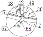
3. The detection device for intelligent manufacturing according to claim 1, wherein the transmission device comprises a circular frame (46) arranged on the lower side of the mounting cylinder (7) at the lowest position of the detection plate (14), the circular frame (46) and the mounting cylinder (7) are coaxially arranged, the inner diameter of the circular frame (46) is larger than the maximum moving distance of the auxiliary plate (42), an end face gear (47) is slidably arranged on the outer circular surface of the circular frame (46), a rotary driven gear (48) rotatably arranged on the circular frame (46) is meshed with the end face gear (47), a rotary driven bevel gear (49) coaxially rotating with the rotary driven gear (48) is arranged on the circular frame (46), a rotary driving bevel gear (50) rotatably arranged on the circular frame (46) is meshed with the rotary driven bevel gear (49), and the rotary driving bevel gear (50) is connected with a rotary driving bevel gear (50) rotatably arranged on the upper end of the support plate (2) through a sixth belt transmission connection (51) And the rotary driving helical gear (51) is meshed with the detection helical gear (5), and an electromagnet (67) facing the detection table (1) is fixedly installed on the outer circular surface of the end face gear (47).
4. A detection device for intelligent manufacturing according to claim 3, wherein an adjusting lead screw (38) is rotatably mounted in the detection plate (14) along the extending direction of the detection plate and the adjusting lead screw (38) is driven by an adjusting motor (39) fixedly mounted on the detection plate (14), the adjusting lead screw (38) is in threaded fit with a moving plate (40) and the moving plate (40) is in sliding fit with the detection plate (14), the second sliding cylinder (15) is fixedly mounted on one side of the moving plate (40) facing the mounting cylinder (7) and an outer detection rack (35) is in sliding fit with the moving plate (40), and the first sliding cylinder (9) is driven by a first electronic telescopic rod (41) fixedly mounted at the tail end of the horizontal part of the detection cylinder (8);
and a fourth electronic telescopic rod (68) is fixedly arranged on the outer circular surface of the end face gear (47), and an electromagnet (67) is fixedly arranged at the tail end of the fourth electronic telescopic rod (68).
5. The detection device for intelligent manufacturing according to claim 4, wherein a plurality of auxiliary plates (42) are arranged on the outer circumferential surface of the mounting cylinder (7) at intervals, the plurality of auxiliary plates (42) are driven by a second electric telescopic rod (43) fixedly arranged on the mounting cylinder (7), and the sliding fit part of the detection plate (14) and the mounting cylinder (7) is positioned between the two auxiliary plates (42).
6. The detection device for intelligent manufacturing according to claim 4, wherein an adjusting lead screw (38) is arranged in the mounting cylinder (7), one end of the adjusting lead screw is sleeved with an adjusting driven bevel gear (52) and the adjusting driven bevel gear (52) is meshed with an adjusting driving bevel gear (53) which is rotatably arranged at the upper end of the detection plate (14), the adjusting driving bevel gear (53) is axially and slidably matched with an adjusting gear (54) which is rotatably arranged at the upper end of the bearing plate (2), the adjusting gear (54) is driven by an adjusting motor (39) which is fixedly arranged at the upper end of the bearing plate (2), the adjusting motor (39) is driven by a seventh belt transmission to be provided with a first marking lead screw (55) which is rotatably arranged on the bearing plate (2), the bearing plate (2) is provided with a second marking lead screw (56) which is transversely arranged at a distance from the first marking lead screw (55), and the second marking lead screw (56) is driven by a marking motor (65) which is fixedly arranged on the bearing plate (2), the first marking lead screw (55) and the second marking lead screw (56) are in threaded fit with a U-shaped frame (57) in vertical sliding fit with the bearing plate (2), marking pens (58) are arranged on two cantilevers of the two U-shaped frames (57), and the recording pen (20) is located on the symmetrical line of the two marking pens (58).
7. The detection device for intelligent manufacturing according to claim 1, wherein a leveling cylinder (59) is arranged at the lower end of the detection table (1), a load bar (60) is universally connected to the leveling cylinder (59) at the axis, a plurality of induction balls (61) are arranged in the leveling cylinder (59) in an encircling mode at intervals, gaps between the induction balls (61) and the load bar (60) are arranged, a plurality of support legs (62) which are in vertical sliding fit with the detection table (1) are arranged at the lower end of the outer circular surface of the detection table (1) in an encircling mode at equal intervals, and the support legs (62) are driven by a third electronic expansion link (63) fixedly installed on the detection table (1).
8. The detection device for intelligent manufacturing according to claim 1, wherein the positioning and clamping device comprises a rotary table (22) which is rotatably installed in the detection table (1) and coaxially rotates with the detection table (1), the rotary table (22) is driven by a positioning motor (23) fixedly installed on the detection table (1), a plurality of inclined sliding chutes (26) are formed in the rotary table (22) in a surrounding manner at intervals, positioning blocks (66) are arranged in the sliding chutes (26) in a sliding manner, a plurality of straight grooves (27) along the radial direction of the detection table (1) are formed in the upper end of the detection table (1) in a surrounding manner at intervals, and the straight grooves (27) are in sliding fit with the positioning blocks (66); the upper end of the detection table (1) is transversely far away from one side of the scroll (21) and is rotatably provided with a second fan-shaped helical gear (28) and the second fan-shaped helical gear (28) is driven by a clamping motor (29) fixedly installed on the detection table (1), the detection table (1) is provided with a clamping helical gear (30) which is transversely far away from one side of the second fan-shaped helical gear (28) and is rotatably provided with a lower clamping lead screw (31) rotating coaxially with the turntable (22) through second belt transmission, the lower clamping lead screw (31) is in threaded fit with a clamping table (32) and is in threaded fit with the vertical sliding fit of the detection table (1), the detection table (1) is provided with an upper clamping lead screw (33) which is transversely far away from one side of the clamping helical gear (30) and is rotatably provided with the upper clamping lead screw (33) and is driven by the clamping motor (29) through third belt transmission, the upper clamping screw rod (33) is in threaded fit with the bearing plate (2).
Priority Applications (1)
| Application Number | Priority Date | Filing Date | Title |
|---|---|---|---|
| CN202011635133.8A CN112525135B (en) | 2020-12-31 | 2020-12-31 | Detection device for intelligent manufacturing |
Applications Claiming Priority (1)
| Application Number | Priority Date | Filing Date | Title |
|---|---|---|---|
| CN202011635133.8A CN112525135B (en) | 2020-12-31 | 2020-12-31 | Detection device for intelligent manufacturing |
Publications (2)
| Publication Number | Publication Date |
|---|---|
| CN112525135A CN112525135A (en) | 2021-03-19 |
| CN112525135B true CN112525135B (en) | 2021-08-10 |
Family
ID=74977276
Family Applications (1)
| Application Number | Title | Priority Date | Filing Date |
|---|---|---|---|
| CN202011635133.8A Active CN112525135B (en) | 2020-12-31 | 2020-12-31 | Detection device for intelligent manufacturing |
Country Status (1)
| Country | Link |
|---|---|
| CN (1) | CN112525135B (en) |
Families Citing this family (7)
| Publication number | Priority date | Publication date | Assignee | Title |
|---|---|---|---|---|
| CN113199442A (en) * | 2021-04-21 | 2021-08-03 | 重庆电讯职业学院 | Wheel hub positioning device for automobile detection |
| CN114733785B (en) * | 2022-04-19 | 2023-08-08 | 桂林航天工业学院 | Automatic casting product size measurement and sorting device |
| CN114993233B (en) * | 2022-08-03 | 2022-10-25 | 山东拓庄医疗设备有限公司 | Nuclear magnetic resonance safe operation production detection equipment for medical equipment |
| CN116202468B (en) * | 2023-05-04 | 2023-08-15 | 牧铭智能制造(山东)有限公司 | Slewing bearing debugging mechanism |
| CN116538901B (en) * | 2023-05-19 | 2023-12-26 | 江苏海宇机械有限公司 | Detection device used after spline shaft manufacturing and forming |
| CN117288137B (en) * | 2023-11-27 | 2024-03-19 | 瓦房店人本轴承制造有限公司 | Bearing inner race aperture detection device |
| CN117450982A (en) * | 2023-12-25 | 2024-01-26 | 泰州市勤峰物资有限公司 | Bicycle rim roundness testing machine |
Citations (11)
| Publication number | Priority date | Publication date | Assignee | Title |
|---|---|---|---|---|
| SU516856A1 (en) * | 1973-01-29 | 1976-06-05 | Каунасский Политехнический Институт | Correction device worm gears |
| EP0379919A2 (en) * | 1989-01-24 | 1990-08-01 | Prvni Brnenska Strojirna Koncernovy Podnik | Device for adjusting a position detector bearing in the axis of a partially cylindrical machine part |
| CN1056744A (en) * | 1991-07-09 | 1991-12-04 | 首都机械厂 | The detection method of circularity and roundness measuring equipment |
| JPH10253345A (en) * | 1997-03-11 | 1998-09-25 | Honda Motor Co Ltd | Method and device for measuring size of bevel gear mechanism |
| DE19940869A1 (en) * | 1998-08-28 | 2000-04-06 | Nsk Ltd | Bearing rigidity evaluation apparatus for evaluating the rigidity of a bearing to which a preload is applied |
| WO2005050129A2 (en) * | 2003-11-21 | 2005-06-02 | Riegl Laser Measurement Systems Gmbh | System for recording an object space |
| JP2006047060A (en) * | 2004-08-03 | 2006-02-16 | Nsk Ltd | Diameter measuring method and measuring device for member having circular peripheral surface |
| CN203364737U (en) * | 2013-07-03 | 2013-12-25 | 洛阳Lyc轴承有限公司 | An apparatus for measuring the circularity of the inner/outer surface of a large/medium-sized bearing ring |
| CN207439363U (en) * | 2017-09-05 | 2018-06-01 | 重庆友好活塞有限公司 | Piston face cylindricity detection device |
| CN207991489U (en) * | 2018-02-06 | 2018-10-19 | 洛阳轴承研究所有限公司 | A kind of running accuracy measuring device of bearing |
| CN110595345A (en) * | 2019-09-24 | 2019-12-20 | 郑州科技学院 | Be used for high-end equipment to make PU pipe detection device |
-
2020
- 2020-12-31 CN CN202011635133.8A patent/CN112525135B/en active Active
Patent Citations (11)
| Publication number | Priority date | Publication date | Assignee | Title |
|---|---|---|---|---|
| SU516856A1 (en) * | 1973-01-29 | 1976-06-05 | Каунасский Политехнический Институт | Correction device worm gears |
| EP0379919A2 (en) * | 1989-01-24 | 1990-08-01 | Prvni Brnenska Strojirna Koncernovy Podnik | Device for adjusting a position detector bearing in the axis of a partially cylindrical machine part |
| CN1056744A (en) * | 1991-07-09 | 1991-12-04 | 首都机械厂 | The detection method of circularity and roundness measuring equipment |
| JPH10253345A (en) * | 1997-03-11 | 1998-09-25 | Honda Motor Co Ltd | Method and device for measuring size of bevel gear mechanism |
| DE19940869A1 (en) * | 1998-08-28 | 2000-04-06 | Nsk Ltd | Bearing rigidity evaluation apparatus for evaluating the rigidity of a bearing to which a preload is applied |
| WO2005050129A2 (en) * | 2003-11-21 | 2005-06-02 | Riegl Laser Measurement Systems Gmbh | System for recording an object space |
| JP2006047060A (en) * | 2004-08-03 | 2006-02-16 | Nsk Ltd | Diameter measuring method and measuring device for member having circular peripheral surface |
| CN203364737U (en) * | 2013-07-03 | 2013-12-25 | 洛阳Lyc轴承有限公司 | An apparatus for measuring the circularity of the inner/outer surface of a large/medium-sized bearing ring |
| CN207439363U (en) * | 2017-09-05 | 2018-06-01 | 重庆友好活塞有限公司 | Piston face cylindricity detection device |
| CN207991489U (en) * | 2018-02-06 | 2018-10-19 | 洛阳轴承研究所有限公司 | A kind of running accuracy measuring device of bearing |
| CN110595345A (en) * | 2019-09-24 | 2019-12-20 | 郑州科技学院 | Be used for high-end equipment to make PU pipe detection device |
Non-Patent Citations (2)
| Title |
|---|
| 基于多超声波传感器的轴承形廓质量检测系统;朱小会等;《仪表技术与传感器》;20190830(第8期);全文 * |
| 基于误差分离的圆柱度仪研发;张正等;《轴承》;20171230(第12期);全文 * |
Also Published As
| Publication number | Publication date |
|---|---|
| CN112525135A (en) | 2021-03-19 |
Similar Documents
| Publication | Publication Date | Title |
|---|---|---|
| CN112525135B (en) | Detection device for intelligent manufacturing | |
| CN205861030U (en) | Bearing end-play testing agency | |
| CN210741291U (en) | Radial circle of axle type part detection device that beats | |
| CN108692666B (en) | Cylinder jacket internal diameter detection device | |
| CN204881583U (en) | Processing axle automatic checkout device | |
| CN113804141B (en) | Outer diameter detector | |
| CN108759758A (en) | A kind of engine bearing clearance detector and measurement method | |
| CN109100137B (en) | NVH of rear axle reduction gear rolls off production line and detects platform | |
| CN103175500A (en) | Axial endplay detection device and detection method | |
| CN115235402A (en) | High-precision detection machine | |
| CN214250916U (en) | Shaft part measuring device with center hole as axis reference | |
| CN107990828B (en) | Quick measuring device for dimension and form and position tolerance of driving axle housing parts | |
| CN107339967B (en) | Roundness measuring instrument | |
| CN105180866A (en) | Automatic two-stage inner diameter and roundness detection mechanism for inner rings of first and second generations of wheel hubs | |
| CN111829479A (en) | Device and method for measuring shape error of inner surface of deep hole of part | |
| CN111912318A (en) | Automatic detection equipment and detection method for inner diameter of automobile casing pipe | |
| CN111307087A (en) | Bearing inner race channel check out test set | |
| CN208458706U (en) | A kind of worm screw detection device | |
| CN206944917U (en) | Out star wheel length and cylindrical automatic detection device | |
| CN206281474U (en) | A kind of positioner for tube-like piece measurement | |
| CN213591134U (en) | Double-tip armature rotor roundness detection mechanism | |
| CN104949643A (en) | Automatic gear shaft outer diameter detecting device | |
| CN110186321B (en) | Gun barrel robot crawling driving system | |
| CN113280709A (en) | Driving device for measuring runout of shaft parts without center holes | |
| CN108458637A (en) | The cubing of on-line measurement heavy spiral bevel gear wheel transverse tooth thickness |
Legal Events
| Date | Code | Title | Description |
|---|---|---|---|
| PB01 | Publication | ||
| PB01 | Publication | ||
| SE01 | Entry into force of request for substantive examination | ||
| SE01 | Entry into force of request for substantive examination | ||
| GR01 | Patent grant | ||
| GR01 | Patent grant |