CN112518002A - High-speed slitting method for battery pole piece with adjustable slitting space - Google Patents
High-speed slitting method for battery pole piece with adjustable slitting space Download PDFInfo
- Publication number
- CN112518002A CN112518002A CN202011544618.6A CN202011544618A CN112518002A CN 112518002 A CN112518002 A CN 112518002A CN 202011544618 A CN202011544618 A CN 202011544618A CN 112518002 A CN112518002 A CN 112518002A
- Authority
- CN
- China
- Prior art keywords
- battery pole
- slitting
- pole piece
- cutter
- lifting
- Prior art date
- Legal status (The legal status is an assumption and is not a legal conclusion. Google has not performed a legal analysis and makes no representation as to the accuracy of the status listed.)
- Withdrawn
Links
Images



Classifications
-
- B—PERFORMING OPERATIONS; TRANSPORTING
- B23—MACHINE TOOLS; METAL-WORKING NOT OTHERWISE PROVIDED FOR
- B23D—PLANING; SLOTTING; SHEARING; BROACHING; SAWING; FILING; SCRAPING; LIKE OPERATIONS FOR WORKING METAL BY REMOVING MATERIAL, NOT OTHERWISE PROVIDED FOR
- B23D15/00—Shearing machines or shearing devices cutting by blades which move parallel to themselves
- B23D15/04—Shearing machines or shearing devices cutting by blades which move parallel to themselves having only one moving blade
-
- B—PERFORMING OPERATIONS; TRANSPORTING
- B23—MACHINE TOOLS; METAL-WORKING NOT OTHERWISE PROVIDED FOR
- B23D—PLANING; SLOTTING; SHEARING; BROACHING; SAWING; FILING; SCRAPING; LIKE OPERATIONS FOR WORKING METAL BY REMOVING MATERIAL, NOT OTHERWISE PROVIDED FOR
- B23D33/00—Accessories for shearing machines or shearing devices
-
- B—PERFORMING OPERATIONS; TRANSPORTING
- B23—MACHINE TOOLS; METAL-WORKING NOT OTHERWISE PROVIDED FOR
- B23D—PLANING; SLOTTING; SHEARING; BROACHING; SAWING; FILING; SCRAPING; LIKE OPERATIONS FOR WORKING METAL BY REMOVING MATERIAL, NOT OTHERWISE PROVIDED FOR
- B23D35/00—Tools for shearing machines or shearing devices; Holders or chucks for shearing tools
- B23D35/005—Adjusting the position of the cutting members
Landscapes
- Engineering & Computer Science (AREA)
- Mechanical Engineering (AREA)
- Battery Electrode And Active Subsutance (AREA)
Abstract
The invention discloses a high-speed battery pole piece slitting device with adjustable slitting intervals, which comprises a rack, a lifting mechanism, an upper slitting mechanism and a lower slitting mechanism, wherein the lifting mechanism is arranged at the top end of the rack; compared with the prior art, the battery pole piece cutting device has the advantages that the upper cutter mechanism and the lower cutter mechanism are respectively provided with the spacing adjusting assemblies, so that different cutting specifications of the battery pole piece can be adapted, the structure is more flexible, the production time for cutting the battery pole piece is greatly saved, the production efficiency is improved, and the production cost is reduced.
Description
Technical Field
The invention relates to a high-speed cutting method of a battery pole piece with adjustable cutting space.
Background
After coating the positive electrode or the negative electrode material and rolling, the battery pole piece is divided and cut into required specification width, the current mode is to use metal as the material to make a dividing cutter, in order to improve the dividing efficiency, at present, there is a battery pole piece dividing and cutting machine, the top of which is provided with an upper cutter, the bottom of which is provided with an inner lower cutter and an outer lower cutter, but the upper cutter and the lower cutter of the pole piece dividing and cutting machine are fixedly arranged, so that the space is not adjustable, when the dividing and cutting specification of the battery pole piece changes, the upper cutter group and the lower cutter group of the dividing and cutting machine need to be integrally replaced, which means that when the specifications of the pole piece are more, a plurality of cutter groups need to be equipped, thus leading to high production cost and low production.
Disclosure of Invention
The invention aims to overcome the defects and provide a high-speed cutting method for battery pole pieces with adjustable cutting space.
In order to achieve the purpose, the invention adopts the following specific scheme:
a high-speed slitting method of a battery pole piece with adjustable slitting space comprises a rack, a lifting mechanism, an upper slitting mechanism and a lower slitting mechanism, wherein the lifting mechanism is arranged at the top end of the rack;
the upper slitting mechanism comprises an upper bearing plate fixed at the output end of the lifting mechanism, two upper slitter cutters symmetrically and slidably connected to the upper bearing plate, and two upper spacing adjusting assemblies symmetrically arranged at two ends of the upper bearing plate, wherein the two upper slitter cutters are respectively provided with an upper slitter blade, the two upper slitter blades are symmetrically arranged, and two ends of each upper slitter cutter are respectively and correspondingly fixedly connected with moving ends of the two upper spacing adjusting assemblies;
lower cutting mechanism locates the lower interval adjusting part at lower loading board both ends including the lower loading board, two symmetry sliding connection that locate the frame bottom at the lower cutter seat and two symmetries of loading board down, the loading board corresponds the feed opening down and is equipped with the unloading breach, two the lower cutter seat is equipped with down-cut blade and pole piece bearing board respectively, two down-cut blade symmetry sets up, two pole piece bearing board symmetry sets up, and corresponds separately and paste and lean on down-cut blade, the both ends of lower cutter seat correspond respectively and hold with two removal of interval adjusting part down and be connected.
The upper spacing adjusting assembly and the lower spacing adjusting assembly respectively comprise a cutter variable-pitch motor, a screw support, a positive and negative screw rod and two movable nuts which are respectively in threaded connection with the two ends of the positive and negative screw rod, the screw support is fixed at the bottom end of the frame, the positive and negative screw rod is rotatably connected onto the screw support, the cutter variable-pitch motor is fixed at one end of the screw support and is in transmission connection with one end of the positive and negative screw rod, two nut fixed blocks are arranged at the ends, close to each other, of the movable nuts, nut fixed blocks are respectively arranged at the two ends of the upper cutter holder and are connected onto the movable nuts of the upper spacing adjusting assembly, nut sleeve blocks are respectively arranged at the two ends of the lower cutter holder, and the nut sleeve blocks are connected onto the movable nuts of the lower.
The lower bearing plate is symmetrically provided with two fixed spring seats, the bottom surfaces of the two lower cutter seats are respectively provided with a sliding spring seat corresponding to the two fixed spring seats, a compression spring is connected between the fixed spring seats and the sliding spring seats, the nut sleeve block is kept to be tightly attached to the flange end surface of the moving nut under the action of the compression spring, the lower cutter seats are symmetrically provided with two extrusion roller groups, and the pole piece bearing plate is positioned between the two extrusion roller groups; the upper cutter holder is symmetrically provided with two inclined ejector blocks, the upper cutter blade is positioned between the two inclined ejector blocks, and the distance between the free end of each inclined ejector block and the upper cutter holder is smaller than the distance between the cutting edge of the upper cutter blade and the upper cutter holder; after the battery pole piece is cut off, the inclined ejecting block is correspondingly contacted and extruded with the extrusion roller set, so that the distance between the two lower cutting blades is increased.
Wherein the inclined ejecting block is provided with an inclined surface; the extrusion roller group comprises a roller seat, a roller shaft and a contact roller, the roller seat is fixed on the lower cutter seat, and the contact roller is rotatably connected to the roller seat through the roller shaft.
The lifting mechanism comprises a lifting cylinder and a lifting plate, the lifting cylinder is fixed at the top end of the rack, the output end of the lifting cylinder faces downwards, and the lifting plate is fixedly connected with the output end of the lifting cylinder; the lifting plate extends upwards to be provided with two guide posts, the two guide posts are located on two opposite angle positions of the lifting plate, and the two guide posts penetrate upwards through the top end of the rack and are connected with the top end of the rack through linear bearings.
The invention has the beneficial effects that: compared with the prior art, the battery pole piece cutting device has the advantages that the upper cutter mechanism and the lower cutter mechanism are respectively provided with the spacing adjusting assemblies, so that different cutting specifications of the battery pole piece can be adapted, the structure is more flexible, the production time for cutting the battery pole piece is greatly saved, the production efficiency is improved, and the production cost is reduced.
Drawings
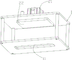
FIG. 1 is a perspective view of the present invention;
FIG. 2 is a schematic view of the lifting mechanism of the present invention mounted on a frame;
FIG. 3 is a schematic structural view of the upper slitting mechanism of the present invention;
FIG. 4 is a schematic view of the lower slitting mechanism of the present invention;
FIG. 5 is an exploded view of the lower slitting mechanism of the present invention;
FIG. 6 is a schematic view of the upper or lower spacing adjustment assembly of the present invention;
description of reference numerals: 1-a frame; 11-a feed opening; 2-a lifting mechanism; 21-a lifting cylinder; 22-a lifter plate; 3, feeding a slitting mechanism; 30-a slanted ejecting block; 31-an upper carrier plate; 32-an upper cutter holder; 33-upper spacing adjustment assembly; 34-an upper cutter blade; 35-nut fixing block; 4-cutting mechanism; 40-extrusion roller group; 41-lower bearing plate; 411-blanking gap; 42-lower cutter seat; 43-lower spacing adjustment assembly; 44-lower cutting blade; 45-pole piece bearing plate; 46-nut block; 47-a fixed spring seat; 48-sliding spring seats; 49-a hold-down spring; 100-cutter pitch motor; 101-screw support; 103-positive and negative tooth screw; 104-moving the nut.
Detailed Description
The invention will be described in further detail with reference to the following figures and specific examples, without limiting the scope of the invention.
As shown in fig. 1 to 6, the high-speed slitting method for a battery pole piece with an adjustable slitting distance in this embodiment includes a frame 1, a lifting mechanism 2, an upper slitting mechanism 3, and a lower slitting mechanism 4, where the lifting mechanism 2 is disposed at the top end of the frame 1, the upper slitting mechanism 3 is disposed at the output end of the lifting mechanism 2, the lower slitting mechanism 4 is disposed at the bottom end of the frame 1 and corresponds to the upper slitting mechanism 3, and a feeding hole 11 is disposed at the bottom end of the frame 1;
the upper splitting mechanism 3 comprises an upper bearing plate 31 fixed at the output end of the lifting mechanism 2, two upper cutter holders 32 symmetrically and slidably connected to the upper bearing plate 31, and two upper spacing adjusting assemblies 33 symmetrically arranged at two ends of the upper bearing plate 31, wherein the two upper cutter holders 32 are respectively provided with an upper cutter blade 34, the two upper cutter blades 34 are symmetrically arranged, and two ends of the upper cutter holder 32 are respectively and correspondingly fixedly connected with moving ends of the two upper spacing adjusting assemblies 33;
Specifically, the two ends of the upper cutter holder 32 and the lower cutter holder 42 are slidably connected to the upper bearing plate 31 and the lower bearing plate 41 through the linear guide and the slider respectively.
The working mode of the embodiment is as follows: when a battery pole piece is cut, the lifting mechanism 2 drives the upper cutting mechanism 3 to move downwards, the upper cutting mechanism 3 is matched with the lower cutting mechanism 4 to cut the battery pole piece, after the battery pole piece is cut off, the lifting mechanism 2 drives the upper cutting mechanism 3 to move upwards, and the cut battery pole piece falls from the feed opening 11 after passing through the feed gap 411; specifically, according to different specifications of the battery pole pieces, the upper spacing adjustment assembly 33 of the upper slitting mechanism 3 adjusts the spacing between the two upper cutter blades 34 by driving the two upper cutter holders 32 to move in opposite directions or move in opposite directions, and the lower spacing adjustment assembly 43 of the lower slitting mechanism 4 adjusts the spacing between the two lower cutter blades 44 by driving the two lower cutter holders 42 to move in opposite directions or move in opposite directions so as to adapt to the specification of the battery pole pieces to be cut at present, after the adjustment is completed, the battery pole pieces are placed on the two pole piece support plates 45 of the lower slitting mechanism 4 and located above the blanking notch 411, and by arranging the pole piece support plates 45, the wrinkle of the battery pole pieces can be avoided, the yield of the cut battery pole pieces is ensured, then the lifting mechanism 2 drives the whole upper slitting mechanism 3 to perform downward probing through the upper bearing plate 31, at this time, the two upper cutter blades 34 are respectively matched with the two lower cutter blades 44, the battery pole pieces are cut, after the cutting of the battery pole pieces is finished, the upper cutting mechanism 3 moves upwards, at the moment, the battery pole pieces between the two lower cutting blades 44 fall into the feed opening 11 of the rack 1 through the feed gap 411 under the dead weight, then fall from the feed opening 11 and are transferred out of a working area, so that the cutting work of the battery pole pieces is finished, and the process is repeated so as to continuously cut the battery pole pieces; for battery pole pieces with different specifications, the cutting requirements of the battery pole pieces with different specifications can be met only by adjusting the distance between the upper cutter set and the lower cutter set through the upper distance adjusting assembly 33 and the lower distance adjusting assembly 43.
The embodiment sets up interval adjusting part respectively on last cutter mechanism and lower cutter mechanism to can adapt to the different specifications of cutting of battery pole piece, the structure is more nimble, saves the production time that battery pole piece was cut greatly, improves production efficiency, reduction in production cost.
In addition, in the embodiment, the cutting edge gap between the lower cutting blade 44 and the upper cutting blade 34 can be adjusted by the upper spacing adjusting assembly 33 and the lower spacing adjusting assembly 43, so that the defects of notch burrs and the like caused by the thickness change of the battery pole piece are avoided, and the cutting effect on the battery pole pieces with different thicknesses is ensured; meanwhile, the size change caused by the sharpening of the cutting edges of the upper cutter blade 34 and the lower cutter blade 44 can also be compensated by the upper spacing adjusting assembly 33 and the lower spacing adjusting assembly 43.
Based on the above embodiment, further, as shown in fig. 2, the lifting mechanism 2 includes a lifting cylinder 21 and a lifting plate 22, the lifting cylinder 21 is fixed at the top end of the frame 1, and the output end of the lifting cylinder faces downward, the lifting plate 22 is fixedly connected with the output end of the lifting cylinder 21, the upper slitting mechanism 3 is driven by the cylinder to slit, and the cost is lower; the lifter plate 22 upwards extends has two guide posts, two the guide post is located two diagonal positions of lifter plate 22, two the guide post upwards passes the top of frame 1, and is connected through linear bearing and the top of frame 1, so sets up, and the last cutting mechanism 3 that makes reciprocates more stably, avoids cutting the in-process and produces the burr defect, guarantees the yields of the battery pole piece after cutting.
Based on the above embodiment, as shown in fig. 3 to fig. 6, each of the upper and lower distance adjusting assemblies 33 and 43 includes a cutter pitch motor 100, a screw bracket 101, a positive and negative threaded rod 103, and two moving nuts 104 respectively threaded at two ends of the positive and negative threaded rod 103, the screw bracket 101 is fixed at the bottom end of the frame 1, the positive and negative threaded rod 103 is rotatably connected to the screw bracket 101, the cutter pitch motor 100 is fixed at one end of the screw bracket 101 and is in transmission connection with one end of the positive and negative threaded rod 103, one end of the two moving nuts 104 close to each other is provided with a flange end face, two ends of the upper cutter holder 32 are respectively provided with a nut fixing block 35, the nut fixing block 35 is connected to the moving nut 104 of the upper distance adjusting assembly 33, two ends of the lower cutter holder 42 are respectively provided with a nut sleeve block 46, the nut block 46 is connected to the traveling nut 104 of the lower spacing adjustment assembly 43. During operation, the upper spacing adjusting assembly 33 and the lower spacing adjusting assembly 43 both drive the positive and negative screw rods 103 to rotate through the cutter variable pitch motor 100, so that the two movable nuts 104 move in opposite directions or move in opposite directions, and then drive the two upper slitting seats and the two lower slitting seats to move, and the purposes of adjusting the spacing between the two upper slitting blades and the spacing between the two lower slitting blades are achieved, so that the battery pole piece slitting machine is suitable for different slitting specifications of battery pole pieces. In the embodiment, the screw rods 103 with positive and negative teeth are used for adjusting the blade spacing, the symmetry is good, and the screw thread self-locking function ensures the rigidity of the upper cutting blade 34 and the lower cutting blade 44.
Based on the above embodiment, further, as shown in fig. 4 to 6, the nut sleeve block 46 is movably sleeved on the moving nut 104 of the lower distance adjusting assembly 43, the lower bearing plate 41 is symmetrically provided with two fixed spring seats 47, the bottom surfaces of the two lower cutter seats 42 are respectively provided with sliding spring seats 48 corresponding to the two fixed spring seats 47, a compression spring 49 is connected between the fixed spring seats 47 and the sliding spring seats 48, under the action of the compression spring 49, the nut sleeve block 46 keeps clinging to the flange end surface of the moving nut 104, the lower cutter seats 42 are symmetrically provided with two extrusion roller sets 40, and the pole piece supporting plate 45 is located between the two extrusion roller sets 40; as shown in fig. 3, the upper cutter holder 32 is symmetrically provided with two inclined ejector blocks 30, the upper cutter blade 34 is positioned between the two inclined ejector blocks 30, and the distance between the free end of the inclined ejector block 30 and the upper cutter holder 32 is smaller than the distance between the cutting edge of the upper cutter blade 34 and the upper cutter holder 32; after the battery pole pieces are cut off, the inclined ejecting block 30 is correspondingly contacted and extruded with the extrusion roller set 40, so that the distance between the two lower cutting blades 44 is increased.
When the battery pole piece cutting device is in actual use, after the battery pole piece is cut off, the inclined jacking block 30 of the upper slitting mechanism 3 and the extrusion roller group 40 of the lower slitting mechanism 4 are respectively matched correspondingly to overcome the elasticity of the compression spring 49 to jack the two lower cutter seats 42, at the moment, the lower cutter seats 42 drive the nut sleeve block 46 to move relative to the moving nut 104 to slide, so that the distance between the two lower cutter blades 44 is enlarged, the cut battery pole piece can fall off from between the two lower cutter blades 44 conveniently, smooth blanking is ensured, and the phenomenon that the cut battery pole piece is clamped between the two lower cutter blades 44 is avoided; preferably, two compression springs 49 are connected between the fixed spring seat 47 and the sliding spring seat 48 to ensure the rigidity requirement of the lower slitting blade when the battery pole piece is slit. In this embodiment, the distance between the free end of the slanted ejecting block 30 and the upper cutter seat 32 is smaller than the distance between the cutting edge of the upper cutter blade 34 and the upper cutter seat 32, that is, the joint point of the slanted ejecting block 30 and the pressing roller set 40 is located behind the cut-off point of the battery pole piece, so as to ensure that the battery pole piece is cut.
Based on the above embodiment, further, the inclined top block 30 has an inclined surface; the extrusion roller set 40 includes a roller seat, a roller shaft and a contact roller, the roller seat is fixed on the lower cutter seat 42, and the contact roller is rotatably connected to the roller seat through the roller shaft. During operation, the upper cutting blade 34 and the lower cutting blade 44 cooperate to cut off the battery pole piece, the inclined surface of the inclined ejecting block 30 abuts against the contact roller of the extrusion roller set 40, and the extrusion force is applied to the extrusion roller set 40, so that the two lower cutting knife bases slide relative to the lower bearing plate 41 after overcoming the elasticity of the compression spring 49, namely, the distance between the two lower cutting blades is increased, and the cut-off battery pole piece falls off from the blanking notch 411.
The above description is only a preferred embodiment of the present invention, and all equivalent changes or modifications of the structure, characteristics and principles described in the present patent application are included in the protection scope of the present patent application.
Claims (6)
1. The high-speed battery pole piece slitting device with the adjustable slitting space is characterized by comprising a rack (1), a lifting mechanism (2), an upper slitting mechanism (3) and a lower slitting mechanism (4), wherein the lifting mechanism (2) is arranged at the top end of the rack (1), the upper slitting mechanism (3) is arranged at the output end of the lifting mechanism (2), the lower slitting mechanism (4) is arranged at the bottom end of the rack (1) and corresponds to the upper slitting mechanism (3), and a blanking port (11) is arranged at the bottom end of the rack (1); the upper splitting mechanism (3) comprises an upper bearing plate (31) fixed at the output end of the lifting mechanism (2), two upper cutter seats (32) symmetrically and slidably connected to the upper bearing plate (31) and two upper spacing adjusting components (33) symmetrically arranged at two ends of the upper bearing plate (31), the two upper cutter seats (32) are respectively provided with an upper cutter blade (34), the two upper cutter blades (34) are symmetrically arranged, and two ends of each upper cutter seat (32) are respectively and correspondingly fixedly connected with moving ends of the two upper spacing adjusting components (33);
the lower cutting mechanism (4) comprises a lower bearing plate (41) arranged at the bottom end of the rack (1), two lower cutter seats (42) symmetrically and slidably connected to the lower bearing plate (41) and two lower distance adjusting components (43) symmetrically arranged at two ends of the lower bearing plate (41), the lower bearing plate (41) is provided with a blanking gap (411) corresponding to the blanking port (11), the two lower cutter seats (42) are respectively provided with a lower cutter blade (44) and a pole piece bearing plate (45), the two lower cutter blades (44) are symmetrically arranged, the two pole piece bearing plates (45) are symmetrically arranged and respectively and correspondingly attached to the lower cutter blade (44), and two ends of the lower cutter seats (42) are respectively correspondingly connected with moving ends of the two lower distance adjusting components (43); the upper spacing adjusting assembly (33) and the lower spacing adjusting assembly (43) respectively comprise a cutter variable-pitch motor (100), a screw rod support (101), a positive and negative screw rod (103) and two movable nuts (104) which are respectively in threaded connection with the two ends of the positive and negative screw rod (103), the screw rod support (101) is fixed at the bottom end of the rack (1), the positive and negative screw rod (103) is rotatably connected to the screw rod support (101), the cutter variable-pitch motor (100) is fixed at one end of the screw rod support (101) and is in transmission connection with one end of the positive and negative screw rod (103), one ends of the two movable nuts (104) close to each other are provided with flange end faces, the two ends of the upper cutter seat (32) are respectively provided with a nut fixing block (35), the nut fixing block (35) is connected to the movable nuts (104) of the upper spacing adjusting assembly (33), and the two ends of the lower cutter seat (42) are respectively, the nut sleeve block (46) is connected to a movable nut (104) of the lower spacing adjusting assembly (43);
when a battery pole piece is cut, the lifting mechanism 2 drives the upper cutting mechanism 3 to move downwards, the upper cutting mechanism 3 is matched with the lower cutting mechanism 4 to cut the battery pole piece, after the battery pole piece is cut off, the lifting mechanism 2 drives the upper cutting mechanism 3 to move upwards, and the cut battery pole piece falls from the feed opening 11 after passing through the feed gap 411; specifically, according to different specifications of the battery pole pieces, the upper spacing adjustment assembly 33 of the upper slitting mechanism 3 adjusts the spacing between the two upper cutter blades 34 by driving the two upper cutter holders 32 to move in opposite directions or move in opposite directions, and the lower spacing adjustment assembly 43 of the lower slitting mechanism 4 adjusts the spacing between the two lower cutter blades 44 by driving the two lower cutter holders 42 to move in opposite directions or move in opposite directions so as to adapt to the specification of the battery pole pieces to be cut at present, after the adjustment is completed, the battery pole pieces are placed on the two pole piece support plates 45 of the lower slitting mechanism 4 and located above the blanking notch 411, and by arranging the pole piece support plates 45, the wrinkle of the battery pole pieces can be avoided, the yield of the cut battery pole pieces is ensured, then the lifting mechanism 2 drives the whole upper slitting mechanism 3 to perform downward probing through the upper bearing plate 31, at this time, the two upper cutter blades 34 are respectively matched with the two lower cutter blades 44, the battery pole pieces are cut, after the cutting of the battery pole pieces is finished, the upper cutting mechanism 3 moves upwards, at the moment, the battery pole pieces between the two lower cutting blades 44 fall into the feed opening 11 of the rack 1 through the feed gap 411 under the dead weight, then fall from the feed opening 11 and are transferred out of a working area, so that the cutting work of the battery pole pieces is finished, and the process is repeated so as to continuously cut the battery pole pieces; for battery pole pieces with different specifications, the cutting requirements of the battery pole pieces with different specifications can be met only by adjusting the distance between the upper cutter set and the lower cutter set through the upper distance adjusting assembly 33 and the lower distance adjusting assembly 43.
2. The high-speed slitting method of battery pole pieces with adjustable slitting pitches as claimed in claim 1, it is characterized in that the nut sleeve block (46) is movably sleeved on a movable nut (104) of the lower spacing adjusting component (43), the lower bearing plate (41) is symmetrically provided with two fixed spring seats (47), the bottom surfaces of the two lower cutter seats (42) are respectively provided with a sliding spring seat (48) corresponding to the two fixed spring seats (47), a pressing spring (49) is connected between the fixed spring seat (47) and the sliding spring seat (48), under the action of the compression spring (49), the nut sleeve block (46) keeps close contact with the flange end face of the movable nut (104), the lower cutter seat (42) is symmetrically provided with two extrusion roller groups (40), and the pole piece bearing plate (45) is positioned between the two extrusion roller groups (40); the upper cutter holder (32) is symmetrically provided with two inclined ejector blocks (30), the upper cutter blade (34) is positioned between the two inclined ejector blocks (30), and the distance between the free end of each inclined ejector block (30) and the upper cutter holder (32) is smaller than the distance between the cutting edge of the upper cutter blade (34) and the upper cutter holder (32); after the battery pole piece is cut off, the inclined ejecting block (30) is correspondingly contacted and extruded with the extrusion roller group (40), so that the distance between the two lower cutting blades (44) is increased.
3. The high-speed battery pole piece slitting method with the adjustable slitting distance as claimed in claim 2, wherein the inclined top block (30) is provided with an inclined surface; the extrusion roller group (40) comprises a roller seat, a roller shaft and a contact roller, the roller seat is fixed on the lower cutter seat (42), and the contact roller is rotatably connected to the roller seat through the roller shaft.
4. The high-speed battery pole piece slitting method with the adjustable slitting distance according to claim 1, characterized in that the lifting mechanism (2) comprises a lifting cylinder (21) and a lifting plate (22), the lifting cylinder (21) is fixed at the top end of the frame (1), the output end of the lifting cylinder faces downwards, and the lifting plate (22) is fixedly connected with the output end of the lifting cylinder (21); the lifting plate (22) extends upwards to form two guide columns, the two guide columns are located on two opposite angle positions of the lifting plate (22), and the two guide columns penetrate through the top end of the rack (1) upwards and are connected with the top end of the rack (1) through linear bearings.
5. The high-speed battery pole piece slitting method with the adjustable slitting distance according to claim 1, characterized in that the lifting mechanism (2) comprises a lifting cylinder (21) and a lifting plate (22), the lifting cylinder (21) is fixed at the top end of the frame (1), the output end of the lifting cylinder faces downwards, and the lifting plate (22) is fixedly connected with the output end of the lifting cylinder (21); the lifting plate (22) extends upwards to form two guide columns, the two guide columns are located on two opposite angle positions of the lifting plate (22), and the two guide columns penetrate through the top end of the rack (1) upwards and are connected with the top end of the rack (1) through linear bearings.
6. The high-speed battery pole piece slitting method with the adjustable slitting distance according to claim 1, characterized in that the lifting mechanism (2) comprises a lifting cylinder (21) and a lifting plate (22), the lifting cylinder (21) is fixed at the top end of the frame (1), the output end of the lifting cylinder faces downwards, and the lifting plate (22) is fixedly connected with the output end of the lifting cylinder (21); the lifting plate (22) extends upwards to form two guide columns, the two guide columns are located on two opposite angle positions of the lifting plate (22), and the two guide columns penetrate through the top end of the rack (1) upwards and are connected with the top end of the rack (1) through linear bearings.
Priority Applications (1)
| Application Number | Priority Date | Filing Date | Title |
|---|---|---|---|
| CN202011544618.6A CN112518002A (en) | 2020-03-04 | 2020-03-04 | High-speed slitting method for battery pole piece with adjustable slitting space |
Applications Claiming Priority (2)
| Application Number | Priority Date | Filing Date | Title |
|---|---|---|---|
| CN202011544618.6A CN112518002A (en) | 2020-03-04 | 2020-03-04 | High-speed slitting method for battery pole piece with adjustable slitting space |
| CN202010142855.3A CN111168137B (en) | 2020-03-04 | 2020-03-04 | A high-speed slitting device for battery pole pieces with adjustable slitting distance |
Related Parent Applications (1)
| Application Number | Title | Priority Date | Filing Date |
|---|---|---|---|
| CN202010142855.3A Division CN111168137B (en) | 2020-03-04 | 2020-03-04 | A high-speed slitting device for battery pole pieces with adjustable slitting distance |
Publications (1)
| Publication Number | Publication Date |
|---|---|
| CN112518002A true CN112518002A (en) | 2021-03-19 |
Family
ID=70619397
Family Applications (2)
| Application Number | Title | Priority Date | Filing Date |
|---|---|---|---|
| CN202011544618.6A Withdrawn CN112518002A (en) | 2020-03-04 | 2020-03-04 | High-speed slitting method for battery pole piece with adjustable slitting space |
| CN202010142855.3A Active CN111168137B (en) | 2020-03-04 | 2020-03-04 | A high-speed slitting device for battery pole pieces with adjustable slitting distance |
Family Applications After (1)
| Application Number | Title | Priority Date | Filing Date |
|---|---|---|---|
| CN202010142855.3A Active CN111168137B (en) | 2020-03-04 | 2020-03-04 | A high-speed slitting device for battery pole pieces with adjustable slitting distance |
Country Status (1)
| Country | Link |
|---|---|
| CN (2) | CN112518002A (en) |
Cited By (2)
| Publication number | Priority date | Publication date | Assignee | Title |
|---|---|---|---|---|
| CN114030025A (en) * | 2021-10-09 | 2022-02-11 | 江苏中关村嘉拓新能源设备有限公司 | Full-automatic distance-changing slitting knife mechanism and full-automatic distance-changing method |
| CN117260863A (en) * | 2023-10-18 | 2023-12-22 | 山西华钠铜能科技有限责任公司 | Cutter mechanism and sagger cutting device |
Families Citing this family (3)
| Publication number | Priority date | Publication date | Assignee | Title |
|---|---|---|---|---|
| CN111482646A (en) * | 2020-04-22 | 2020-08-04 | 绍兴宾果科技有限公司 | Rack type anti-jamming battery pole piece cutting robot and cutting method |
| CN113001231B (en) * | 2021-03-03 | 2024-07-12 | 安徽德亚电池有限公司 | Cutting device is used in production of electricity core pole piece |
| CN117415367A (en) * | 2023-11-24 | 2024-01-19 | 江西金泰合新材料科技有限公司 | A fixed-length cutting device and method for non-ferrous metal smelting and rolling products |
Family Cites Families (10)
| Publication number | Priority date | Publication date | Assignee | Title |
|---|---|---|---|---|
| CN201689932U (en) * | 2009-12-30 | 2010-12-29 | 邢台市粮食机械有限责任公司 | Edge-cutting device of battery pole-piece |
| DE102011089818A1 (en) * | 2011-12-23 | 2013-06-27 | Achenbach Buschhütten GmbH & Co. KG | Cutting device and method for cutting sheet metal or block material |
| CN203711984U (en) * | 2014-02-28 | 2014-07-16 | 金川集团股份有限公司 | Shearing tool applied to nickel starting sheets |
| CN105436681B (en) * | 2016-01-13 | 2018-05-25 | 成都焊研科技有限责任公司 | Thin plate full-automatic narrow overlap resistance seam welder |
| CN106424891B (en) * | 2016-12-12 | 2018-11-20 | 安徽鲲鹏装备模具制造有限公司 | A kind of belt end trimming takes the door shell cutting machine of long function |
| CN107803664A (en) * | 2017-11-21 | 2018-03-16 | 东莞理工学院 | A battery pole piece cutting and welding all-in-one machine |
| CN207655997U (en) * | 2017-12-18 | 2018-07-27 | 烟台慧安达环保装备技术有限公司 | Motor-driven knife roll-setting gear and gantry cutter with it are sheared in a kind of gantry |
| CN108355989B (en) * | 2018-02-23 | 2020-01-03 | 南陵旺科知识产权运营有限公司 | A utmost point ear cuts and detects letter sorting mechanism for electronic product battery |
| CN208514552U (en) * | 2018-06-20 | 2019-02-19 | 深圳市东彩自动化科技有限公司 | A kind of hi-precision cutting machine that can easily be accommodated |
| CN109802166A (en) * | 2019-01-21 | 2019-05-24 | 任磊 | A kind of preparation process of new energy battery and its dedicated pole piece cutting apparatus |
-
2020
- 2020-03-04 CN CN202011544618.6A patent/CN112518002A/en not_active Withdrawn
- 2020-03-04 CN CN202010142855.3A patent/CN111168137B/en active Active
Cited By (4)
| Publication number | Priority date | Publication date | Assignee | Title |
|---|---|---|---|---|
| CN114030025A (en) * | 2021-10-09 | 2022-02-11 | 江苏中关村嘉拓新能源设备有限公司 | Full-automatic distance-changing slitting knife mechanism and full-automatic distance-changing method |
| CN114030025B (en) * | 2021-10-09 | 2023-09-26 | 江苏嘉拓新能源智能装备股份有限公司 | Full-automatic variable-pitch slitting mechanism and full-automatic variable-pitch method |
| CN117260863A (en) * | 2023-10-18 | 2023-12-22 | 山西华钠铜能科技有限责任公司 | Cutter mechanism and sagger cutting device |
| CN117260863B (en) * | 2023-10-18 | 2026-02-27 | 山西华钠铜能科技有限责任公司 | Cutting mechanism and sagger cutting device |
Also Published As
| Publication number | Publication date |
|---|---|
| CN111168137B (en) | 2021-04-27 |
| CN111168137A (en) | 2020-05-19 |
Similar Documents
| Publication | Publication Date | Title |
|---|---|---|
| CN111168137B (en) | A high-speed slitting device for battery pole pieces with adjustable slitting distance | |
| CN105904292B (en) | Rotary disc type full-automatic blade grinding machine | |
| CN111185635B (en) | Battery pole piece high-speed slitting complete set of assembly line equipment | |
| CN112589850A (en) | Corrugated container board refabrication processing system | |
| CN205834369U (en) | High-velocity wire cutting circular sawing machine | |
| CN112606050A (en) | Corrugated board re-preparation processing method | |
| CN219169713U (en) | Plate shearing machine with location structure | |
| CN219188851U (en) | Angle-adjustable trimming machine | |
| CN117259838A (en) | Steel grating shearing equipment and shearing method | |
| CN106001757A (en) | High-speed metal cutting circular saw | |
| CN205519846U (en) | Sheet metal keyway planer | |
| CN212241400U (en) | Wood cutting equipment | |
| CN109866260B (en) | Film cutting machine | |
| CN222430947U (en) | A blade assembly device with adjustable width and height | |
| CN119819992B (en) | Aluminum plate trimming and shearing device | |
| CN223369520U (en) | Automatic feeding and cutting machine for lithium battery | |
| CN219503799U (en) | Plate shearing machine for steel structure machining | |
| CN218192584U (en) | Roller disassembly-free grooving device for multi-line cutting equipment | |
| CN213495949U (en) | Puncher that can accurate punch | |
| CN223801692U (en) | Cutting machine for battery electrode slice processing | |
| CN218692793U (en) | Steel plate pre-flanging machine | |
| CN223455144U (en) | Split type inductance electrode cutting mechanism | |
| CN221318653U (en) | PET film cutting and slitting device | |
| CN111086034B (en) | A processing device for 45° cutting of the long side of a countertop | |
| CN120038369B (en) | Automatic change hull coil of strip slitting cutting device |
Legal Events
| Date | Code | Title | Description |
|---|---|---|---|
| PB01 | Publication | ||
| PB01 | Publication | ||
| SE01 | Entry into force of request for substantive examination | ||
| SE01 | Entry into force of request for substantive examination | ||
| WW01 | Invention patent application withdrawn after publication | ||
| WW01 | Invention patent application withdrawn after publication |
Application publication date: 20210319 |