CN112517733A - Reverse precision cutting die and method for automotive highlight metal decorating part - Google Patents
Reverse precision cutting die and method for automotive highlight metal decorating part Download PDFInfo
- Publication number
- CN112517733A CN112517733A CN202011565686.0A CN202011565686A CN112517733A CN 112517733 A CN112517733 A CN 112517733A CN 202011565686 A CN202011565686 A CN 202011565686A CN 112517733 A CN112517733 A CN 112517733A
- Authority
- CN
- China
- Prior art keywords
- reverse
- die
- pushing block
- base
- upper die
- Prior art date
- Legal status (The legal status is an assumption and is not a legal conclusion. Google has not performed a legal analysis and makes no representation as to the accuracy of the status listed.)
- Granted
Links
Images


Classifications
-
- B—PERFORMING OPERATIONS; TRANSPORTING
- B21—MECHANICAL METAL-WORKING WITHOUT ESSENTIALLY REMOVING MATERIAL; PUNCHING METAL
- B21D—WORKING OR PROCESSING OF SHEET METAL OR METAL TUBES, RODS OR PROFILES WITHOUT ESSENTIALLY REMOVING MATERIAL; PUNCHING METAL
- B21D28/00—Shaping by press-cutting; Perforating
- B21D28/02—Punching blanks or articles with or without obtaining scrap; Notching
- B21D28/14—Dies
-
- B—PERFORMING OPERATIONS; TRANSPORTING
- B21—MECHANICAL METAL-WORKING WITHOUT ESSENTIALLY REMOVING MATERIAL; PUNCHING METAL
- B21D—WORKING OR PROCESSING OF SHEET METAL OR METAL TUBES, RODS OR PROFILES WITHOUT ESSENTIALLY REMOVING MATERIAL; PUNCHING METAL
- B21D43/00—Feeding, positioning or storing devices combined with, or arranged in, or specially adapted for use in connection with, apparatus for working or processing sheet metal, metal tubes or metal profiles; Associations therewith of cutting devices
- B21D43/003—Positioning devices
Landscapes
- Engineering & Computer Science (AREA)
- Mechanical Engineering (AREA)
- Punching Or Piercing (AREA)
Abstract
The invention relates to a reverse finish cutting die and method for a vehicle highlight metal decorating part, and the reverse finish cutting die comprises an upper die base, a lower die base, a material pressing positioning mechanism and a reverse inclined wedge mechanism, wherein the material pressing positioning mechanism comprises an upper die fixing base fixed on the lower side of the upper die base and a lower die fixing base fixedly arranged on the lower die base, a lower die core used for supporting the decorating part is arranged on the upper side of the lower die fixing base, a material pressing base is arranged on the lower side of the upper die fixing base, a material pressing plate used for pressing the decorating part is arranged on the lower side of the material pressing base, and a cutter controlled to ascend by the reverse inclined wedge mechanism to die the end. The vehicle highlight metal decorating part reverse finish cutting die is reasonable in design, the die structure is optimized, the service life of the whole die is prolonged, the phenomenon that the production period is delayed due to line breakage during mass production of products is avoided, the mass production rate of the products is ensured, the punching mode is changed, burrs of the products during punching can be reduced or even avoided, and the appearance quality of the products is improved.
Description
Technical Field
The invention relates to a reverse precision cutting die and method for a vehicle highlight metal decorating part.
Background
The cross section of the automotive highlight metal decorating part is arched, the existing automotive highlight metal decorating part end finish cutting die adopts a structure of punching an end from top to bottom, a product is fixed and pressed by a pressure plate and a lower die core in the punching process, the lower die core and a cutter are knife edges, and the cutter is driven to punch the end of the product from top to bottom so as to achieve the effect of finish cutting the end of the product; because of the product lateral wall limit height can't guarantee to reach the digifax size at the actual mould in-process of transferring, so the lower mould benevolence need do and dodge in product end both sides limit department, the dodge of here will lead to product end both sides burr and the surperficial light variation phenomenon of product to appear in die-cut in-process, need mould debugging personnel to carry out many rounds of repaiies and join in marriage just can solve product appearance problem, the lower mould benevolence supports product department structure less, lead to cutter edge of a knife and lower mould benevolence to crack easily, lead to the product to break the line in process of production, influence.
Disclosure of Invention
In view of the above, the present invention provides a reverse precision cutting mold and method for a vehicle highlight metal decoration, which optimizes the mold structure, prolongs the overall service life of the mold, and ensures the mass production rate of the product.
The invention is realized by adopting the following scheme: the utility model provides a reverse accurate mould of cutting of automotive highlight metal decoration, includes upper die base, die holder, presses material positioning mechanism and is located the reverse mechanism of carving to one side at material positioning mechanism rear, press material positioning mechanism including being fixed in last mould fixing base and the lower mould fixing base of fixed mounting in the die holder of last mould base downside, lower mould fixing base upside is installed and is used for supporting the lower mould benevolence of decoration, it installs the material pressing seat to go up mould fixing base downside, press the material pressing plate that the material pressing seat downside was installed and is used for compressing tightly the decoration, lower mould benevolence rear side is provided with and carves the cutter of mechanism control rising with die-cut decoration end to one side by reverse.
Further, the reverse inclined wedge mechanism comprises a slotting tool which is vertically arranged and the upper end of the slotting tool is fixedly connected onto the upper die base, the cutter is fixedly installed on a reverse pushing block below the cutter, a pushing block which can slide back and forth is arranged below the middle of the reverse pushing block and the slotting tool, and the pushing block, the reverse pushing block and the slotting tool are matched through 45-degree inclined plane butting so as to enable the reverse pushing block to move upwards through the pushing block when the slotting tool descends.
Further, fixedly connected with is located the stopping piece at slotting tool lower extreme rear on the die holder, stopping piece leading flank and slotting tool lower extreme trailing flank looks butt wear to be equipped with the pull rod that sets up along the fore-and-aft direction in the middle of the stopping piece, the pull rod front end is connected in the promotion fast, and the cover is equipped with the reset spring who promotes the pull rod backward on the pull rod, and stopping piece front side is provided with the buffer block.
Furthermore, wear-resisting plates are arranged on the front side of the stopping block and the inclined planes of the front side and the rear side of the pushing block, a sliding groove is formed in the bottom of the pushing block, and a guide block which is in sliding fit with the sliding groove which is pushed quickly is arranged on the lower die fixing seat; the lower parts of two sides of the pushing block are provided with protruding guide rails, and the lower die fixing seat is fixedly connected with an L-shaped pressing block which is pressed with the protruding guide rails of the pushing block and is in sliding fit with the protruding guide rails.
Furthermore, a material pressing spring is arranged between the material pressing seat and the upper die fixing seat; two sides of the material pressing seat are connected with draw hooks extending upwards, and two sides of the upper die fixing seat are provided with hook grooves which are in hooking fit with hook parts at the upper ends of the draw hooks; the lower side of the pressing seat is provided with limiting cones located on two sides of the pressing plate, and the upper side of the lower die fixing seat is provided with a conical hole matched with the limiting cones.
Further, the notch that is used for the reverse promotion piece of installation is offered at lower mould fixing base rear portion, lower mould benevolence rear end stretches into in the notch, vertical guide slot has been seted up to notch both sides inner wall, the fast both sides of reverse promotion are provided with vertical guide slot sliding fit's guide block, and the lower mould fixing base is provided with the chip groove in notch upper end one side, set up the chip removal hole that is located the discharge end below of discharge groove on the die holder, the die holder below is provided with and is used for collecting the drawer box that falls the cuttings and can outwards take out from the chip removal hole.
Furthermore, the lower end of the reverse pushing block is connected with a cutter retracting spring which pulls the reverse pushing block to reset downwards, and the lower die fixing seat is fixedly connected with a backstop baffle which is located below the reverse pushing block and used for limiting the descending distance.
Further, the lower mould benevolence upper flank is for upwards swelling and with the protruding face of encircleing of decoration concave surface looks adaptation, presses the flitch downside to be upwards concave and with the concave face of encircleing of decoration convex surface looks adaptation, the cutting edge portion of cutter is also protruding arch to the distance between cutter cutting edge portion and the lower mould benevolence arch face gradually diminishes to both ends by the centre.
The other technical scheme of the invention is as follows: the processing method of the reverse finish cutting die for the automotive high-gloss metal decorating part comprises the following steps: (1) placing the product decoration part on the lower die core with the concave surface facing downwards; (2) the punch is matched, the upper die base moves downwards to drive the upper die fixing base to move downwards, and the upper die fixing base drives the material pressing base to move downwards together to enable the material pressing plate to tightly press and fix the decorating part; (3) the upper die base continues to move downwards to drive the slotting tool to push the pushing block downwards so that the pushing block moves forwards, and the pushing block is in contact with the reverse pushing block in the advancing process and pushes the reverse pushing block to drive the cutter to move upwards together to punch the product; (4) and (3) opening the die of the punch, wherein the upper die base moves upwards to drive the upper die fixing base, the pressing base and the pressing plate to move upwards to loosen the decorating part, and simultaneously, the slotting tool is driven to move upwards, and the cutting tool moves downwards to retract the cutting tool.
Compared with the prior art, the invention has the following beneficial effects: the vehicle highlight metal decorating part reverse finish cutting die is reasonable in design, the die structure is optimized, the service life of the whole die is prolonged, the phenomenon that the production period is delayed due to line breakage during mass production of products is avoided, the mass production rate of the products is ensured, the punching mode is changed, burrs of the products during punching can be reduced or even avoided, and the appearance quality of the products is improved.
In order to make the objects, technical solutions and advantages of the present invention more apparent, the present invention will be described in further detail below with reference to specific embodiments and accompanying drawings.
Drawings
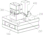
FIG. 1 is a perspective view of the overall structure of an embodiment of the present invention;
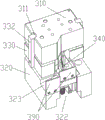
FIG. 2 is a schematic view of a swaging positioning mechanism and a reverse cam mechanism in an embodiment of the invention;
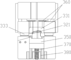
FIG. 3 is a longitudinal cross-sectional view of FIG. 2;
FIG. 4 is a perspective view of a swage positioning mechanism in an embodiment of the invention;
FIG. 5 is a rear view of the swage positioning mechanism in the embodiment of the invention;
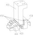
FIG. 6 is a perspective view of a reverse wedge mechanism in an embodiment of the present invention;
the reference numbers in the figures illustrate: 100-upper die holder, 200-lower die holder, 210-chip removal hole, 300-material pressing positioning mechanism, 310-upper die fixing seat, 311-hook groove, 320-lower die fixing seat, 321-lower die core, 322-notch, 323-chip groove, 330-material pressing seat, 331-material pressing plate, 332-draw hook, 333-limiting cone, 340-cutter, 350-reverse pushing block, 360-material pressing spring, 370-retracting spring, 380-backstop baffle, 390-material baffle, 400-reverse inclined wedge mechanism, 410-slotting cutter, 420-pushing block, 430-backstop block, 440-pull rod, 441-reset spring, 450-wear-resisting plate, 460-L-shaped pressing block and 500-drawer box.
Detailed Description
As shown in fig. 1 to 6, a reverse precision cutting die for a high-gloss metal decorating part for a vehicle comprises an upper die holder 100, a lower die holder 200, a pressing and positioning mechanism 300 and a reverse slanting wedge mechanism 400 located behind the pressing and positioning mechanism, wherein the pressing and positioning mechanism 300 comprises an upper die fixing base 310 fixed on the lower side of the upper die holder and a lower die fixing base 320 fixedly installed on the lower die holder, a lower die core 321 for supporting the decorating part is installed on the upper side of the lower die fixing base 320, a pressing base 330 is installed on the lower side of the upper die fixing base 310, a pressing plate 331 for pressing the decorating part is installed on the lower side of the pressing base 330, the pressing plate is installed on the pressing base 330 by bolts and pins, the lower die core is installed on the lower die fixing base 320 by bolts and pins, the rear ends of the pressing plate and the lower die core are flush, a cutter 340 controlled by the reverse slanting wedge mechanism 400 to ascend to, the concave surface of the decorative part of the processed product is placed downwards on the lower die core, the concave surface of the lower side of the decorative part is attached to the upper side surface of the lower die core, the end of the decorative part extends out of the rear end of the lower die core, the decorative part is firstly pressed by the pressure plate in the die assembly process, then the cutter is pushed by the upper die base through the reverse inclined wedge mechanism 400 to move upwards to punch the end of the decorative part, and the pressure plate and the cutter are used as the knife edges in the structure from bottom to top, so that the line type of the knife edge of the cutter is optimized, the punching force applied to the knife edge in the punching process is reduced, burrs of the product in the punching process can be reduced or even; the reverse supporting force is provided by the pressure plate during punching, so that the breakage of the lower mold core in the production process is avoided, the whole service life of the mold is prolonged, and the mass production rate of the product is ensured.
In this embodiment, the upper side of the lower die core is a convex arch surface which is upwardly raised and is matched with the concave surface of the decorating part, the lower side of the pressure plate is a concave arch surface which is upwardly concave and is matched with the convex surface of the decorating part, the blade part of the cutter is also in a convex arch shape, the distance between the cutting edge part of the cutter and the convex arch surface of the lower die core is gradually reduced from the middle to the two ends, the draft angle of the cutting edge part of the cutter is 50 degrees, the cutting edge of the cutter is optimized, in the punching process, two ends of the cutting edge part of the cutter firstly contact two sides of the concave surface of the decorating part, the original mode of punching the cross section of the whole product at the same time is changed into the mode of punching at different times, the cutter cutting edge contacts both ends of product cross-section earlier promptly, and die-cut gradually reaches decoration cross-section middle part again, and die-cut process principle is similar to the scissors and tailors the principle, has improved the light distortion phenomenon on product surface well, can not cause the product to appear the outward appearance problem after the end is cut accurately basically.
In this embodiment, the reverse slanting wedge mechanism 400 includes a slotting tool 410 which is vertically arranged and has an upper end fixedly connected to the upper die base, the cutting tool 340 is fixedly mounted on a reverse pushing block 350 below the slotting tool, a pushing block 420 which can slide back and forth is arranged below the middle of the reverse pushing block 350 and the slotting tool 410, the pushing block 420, the reverse pushing block 350 and the slotting tool 410 are matched through 45-degree inclined plane butt so as to enable the reverse pushing block to move upwards through the pushing block when the slotting tool moves downwards, transmission of movement is achieved through the matching of 45-degree inclined planes, the slotting tool moves downwards so that the pushing block moves forwards, and the pushing block moves forwards so that the reverse pushing block moves upwards to drive the cutting tool to complete punching work.
In this embodiment, fixedly connected with is located stopping piece 430 at slotting tool 410 lower extreme rear on die holder 200, stopping piece 430 leading flank and slotting tool lower extreme trailing flank looks butt wear to be equipped with in the middle of stopping piece 430 along the pull rod 440 that the fore-and-aft direction set up, pull rod 440 front end is connected in and is promoted fast on, and the cover is equipped with reset spring 441 that promotes the pull rod backward on pull rod 440, and stop piece is being pushed against to reset spring one end, and the retaining ring of pull rod rear end is being pushed against to the other end, and stopping piece front side is provided with the buffer block, and when the slotting tool went upward, reset spring 441 promoted the pushing block and moved backward and reset.
In the embodiment, the wear-resisting plates 450 are respectively arranged on the front side of the retaining block 430 and the inclined planes of the front side and the rear side of the pushing block 350, the bottom of the pushing block 350 is provided with a chute, and the lower die fixing seat is provided with a guide block which is in sliding fit with the chute which is pushed quickly; the lower parts of the two sides of the pushing block 350 are provided with protruding guide rails, and the lower die fixing seat is fixedly connected with an L-shaped pressing block 460 which is pressed with the protruding guide rails of the pushing block and is in sliding fit with the protruding guide rails, so that the pushing block is ensured to move stably and not to shake.
In this embodiment, a material pressing spring 360 is disposed between the material pressing base 330 and the upper die fixing base 310, the material pressing spring includes a coil spring and a nitrogen spring, and the whole movement process ensures that a product is pressed and fixed on the lower die core and then die-cut by controlling the stroke of the material pressing spring; two sides of the pressing base 330 are connected with upwardly extending draw hooks 332, two sides of the upper die fixing base 310 are provided with hook grooves 311 which are in hooking fit with hook parts at the upper ends of the draw hooks, and when the upper die fixing base moves upwards for a certain distance, the draw hooks hook the hook grooves and then the pressing base is driven by the draw hooks to move upwards together; the lower side of the material pressing seat 330 is provided with a limiting cone 333 positioned at two sides of the material pressing plate, and the upper side of the lower die fixing seat is provided with a conical hole matched with the limiting cone.
In this embodiment, a notch 322 for installing a reverse pushing block is formed in the rear portion of the lower mold fixing seat 320, the rear end of the lower mold core extends into the notch, vertical guide grooves are formed in the inner walls of two sides of the notch, and guide blocks in sliding fit with the vertical guide grooves are arranged on two sides of the reverse pushing block, so that the lower mold core can slide up and down and cannot shake; the lower die fixing seat is provided with a chip removal groove 323 on one side of the upper end of the notch, the lower die base 200 is provided with a chip removal hole 210 below the discharge end of the chip removal groove, a drawer box 500 which is used for collecting powder chips falling from the chip removal hole and can be drawn out outwards is arranged below the lower die base 200, and metal chips generated by punching fall into the drawer box through the chip removal groove and the chip removal hole for collection.
In this embodiment, the rear side of the cutter 340 and the side of the chip discharge groove 323 are provided with a striker plate 390 for preventing reduction of chip cost.
In this embodiment, the fast lower extreme of reverse promotion is connected with and pulls its descending return back sword spring 370 downwards, and fixedly connected with is located the fast below of reverse promotion in order to restrict the descending limit position of down distance of backstop baffle 380, restriction cutter on the lower mould fixing base.
The invention discloses a die cutting process of a reverse fine cutting die of a vehicle highlight metal decorating part, which comprises the following steps: placing the concave surface of the product decoration on the lower die core downwards, driving an upper die fixing seat to move downwards by the downward movement of an upper die base in the die assembly process of the punch press, and driving a material pressing seat by the upper die fixing seat to move downwards together so that a material pressing plate presses and fixes the decoration; the upper die base continues to move downwards to drive the slotting tool to push the pushing block downwards so that the pushing block moves forwards, and the pushing block is in contact with the reverse pushing block in the advancing process and pushes the reverse pushing block to drive the cutter to move upwards together for punching products.
The invention can reduce or even avoid burrs of the product in the punching process, and changes the original mode of simultaneously punching the whole product section into the mode of simultaneously punching at different times by improving the blade section so as to change the punching process, thereby improving the optical distortion phenomenon of the product surface well and basically not causing the appearance problem of the product after the end is finely cut. And the cutter edge strength after optimization is greatly enhanced, the whole service life of the die is prolonged, the phenomenon that the production time limit is delayed due to wire breakage of the product in mass production is avoided, and the economic loss of a large amount of time due to the die problem can be avoided for a product production side. The invention has scientific and reasonable structure, avoids debugging personnel from investing a large amount of time to repair the knife edge, reduces the debugging time of the die, improves the production and modification efficiency of the die, reduces the labor cost invested by a die manufacturing factory, and reduces the delivery time of the die.
The method comprises the following steps: (1) placing the product decoration part on the lower die core with the concave surface facing downwards; (2) the punch is matched, the upper die base moves downwards to drive the upper die fixing base to move downwards, and the upper die fixing base drives the material pressing base to move downwards together to enable the material pressing plate to tightly press and fix the decorating part; (3) the upper die base continues to move downwards to drive the slotting tool to push the pushing block downwards so that the pushing block moves forwards, the pushing block is in contact with the reverse pushing block in the advancing process and pushes the reverse pushing block to drive the cutter to move upwards together to punch and cut a product, and in the punching process, the cutting edge of the cutter is firstly in contact with two ends of the section of the product and then is gradually punched to the middle part of the section of the decorating part; (4) the punch die sinking, the last mould fixing base of upper die base upward movement drive, press material seat and pressure flitch upward movement to loosen the decoration, drive the slotting tool upward movement simultaneously, promote the piece and move backward under the reset spring effect, reverse promotion piece moves down under the spring effect of moving back and drives the cutter and move back the sword downwards.
Any embodiment disclosed herein above is meant to disclose, unless otherwise indicated, all numerical ranges disclosed as being preferred, and any person skilled in the art would understand that: the preferred ranges are merely those values which are obvious or representative of the technical effect which can be achieved. Since the numerical values are too numerous to be exhaustive, some of the numerical values are disclosed in the present invention to illustrate the technical solutions of the present invention, and the above-mentioned numerical values should not be construed as limiting the scope of the present invention.
If the invention discloses or relates to parts or structures which are fixedly connected to each other, the fixedly connected parts can be understood as follows, unless otherwise stated: a detachable fixed connection (for example using bolts or screws) is also understood as: non-detachable fixed connections (e.g. riveting, welding), but of course, fixed connections to each other may also be replaced by one-piece structures (e.g. manufactured integrally using a casting process) (unless it is obviously impossible to use an integral forming process).
In addition, terms used in any technical solutions disclosed in the present invention to indicate positional relationships or shapes include approximate, similar or approximate states or shapes unless otherwise stated.
Any part provided by the invention can be assembled by a plurality of independent components or can be manufactured by an integral forming process.
Finally, it should be noted that the above examples are only used to illustrate the technical solutions of the present invention and not to limit the same; although the present invention has been described in detail with reference to preferred embodiments, those skilled in the art will understand that: modifications to the specific embodiments of the invention or equivalent substitutions for parts of the technical features may be made; without departing from the spirit of the present invention, it is intended to cover all aspects of the invention as defined by the appended claims.
Claims (9)
1. The utility model provides a reverse finishing cut mould of automotive highlight metal decoration which characterized in that: including upper die base, die holder, press material positioning mechanism and be located the reverse mechanism of carving to one side at material positioning mechanism rear, press material positioning mechanism including be fixed in the last mould fixing base of upper die base downside and fixed mounting in the lower mould fixing base of die holder, lower mould fixing base upside is installed and is used for supporting the lower mould benevolence of decoration, it installs the material pressing seat to go up mould fixing base downside, press the material holder downside to install and be used for compressing tightly the flitch of decoration, lower mould benevolence rear side is provided with and carves the cutter of mechanism control rising with die-cut decoration end to one side by reverse.
2. The reverse finishing cut mold of automotive high-gloss metal decoration according to claim 1, characterized in that: the reverse inclined wedge mechanism comprises a slotting tool which is vertically arranged and the upper end of the slotting tool is fixedly connected onto the upper die base, the cutter is fixedly installed on a reverse pushing block below the cutter, a pushing block which can slide back and forth is arranged below the middle of the reverse pushing block and the slotting tool, and the pushing block, the reverse pushing block and the slotting tool are matched through 45-degree inclined plane butt so as to enable the reverse pushing block to move upwards through the pushing block when the slotting tool goes downwards.
3. The reverse finishing cut mold of automotive high-gloss metal decoration according to claim 2, characterized in that: fixedly connected with is located the stopping piece at slotting tool lower extreme rear on the die holder, stopping piece leading flank and slotting tool lower extreme trailing flank looks butt wear to be equipped with the pull rod that sets up along the fore-and-aft direction in the middle of the stopping piece, the pull rod front end is connected in promoting soon, and the cover is equipped with the reset spring who promotes the pull rod backward on the pull rod, and stopping piece front side is provided with the buffer block.
4. The reverse finishing cut mold of automotive high-gloss metal decoration according to claim 3, wherein: wear-resisting plates are arranged on the front side of the stopping block and the inclined planes of the front side and the rear side of the pushing block, a sliding groove is formed in the bottom of the pushing block, and a guide block which is in sliding fit with the sliding groove which pushes the pushing block is arranged on the lower die fixing seat; the lower parts of two sides of the pushing block are provided with protruding guide rails, and the lower die fixing seat is fixedly connected with an L-shaped pressing block which is pressed with the protruding guide rails of the pushing block and is in sliding fit with the protruding guide rails.
5. The reverse finishing cut mold of automotive high-gloss metal decoration according to claim 2, characterized in that: a material pressing spring is arranged between the material pressing seat and the upper die fixing seat; two sides of the material pressing seat are connected with draw hooks extending upwards, and two sides of the upper die fixing seat are provided with hook grooves which are in hooking fit with hook parts at the upper ends of the draw hooks; the lower side of the pressing seat is provided with limiting cones located on two sides of the pressing plate, and the upper side of the lower die fixing seat is provided with a conical hole matched with the limiting cones.
6. The reverse finishing cut mold of automotive high-gloss metal decoration according to claim 2, characterized in that: the notch that is used for the reverse promotion piece of installation is offered at lower mould fixing base rear portion, lower mould benevolence rear end stretches into in the notch, vertical guide slot has been seted up to notch both sides inner wall, the fast both sides of reverse promotion are provided with vertical guide slot sliding fit's guide block, and the lower mould fixing base is provided with the chip groove in notch upper end one side, set up the chip removal hole that is located discharge chute discharge end below on the die holder, the die holder below is provided with and is used for collecting the drawer box that falls the cuttings of chip removal hole and can outwards take out.
7. The reverse finishing cut mold of automotive high-gloss metal decoration according to claim 2, characterized in that: the fast lower extreme of reverse promotion is connected with the withdrawal spring that its downward pulling resets, and fixedly connected with is located the fast below of reverse promotion in order to restrict the backstop baffle of descending distance on the lower mould fixing base.
8. The reverse finishing cut mold of automotive high-gloss metal decoration according to claim 1, characterized in that: the side is for making progress the uplift and with the protruding hunch face of decoration concave surface looks adaptation on the lower mould benevolence, presses the flitch downside to make progress concave and with the concave hunch face of decoration convex surface looks adaptation, the sword portion of cutter is protruding arch also to the distance between the protruding hunch face of cutter sword portion and lower mould benevolence is by middle to both ends diminishing gradually.
9. The method for processing the reverse finish-cutting die for the automotive high-gloss metal decorating part according to claim 2, characterized in that: the method comprises the following steps: (1) placing the product decoration part on the lower die core with the concave surface facing downwards; (2) the punch is matched, the upper die base moves downwards to drive the upper die fixing base to move downwards, and the upper die fixing base drives the material pressing base to move downwards together to enable the material pressing plate to tightly press and fix the decorating part; (3) the upper die base continues to move downwards to drive the slotting tool to push the pushing block downwards so that the pushing block moves forwards, and the pushing block is in contact with the reverse pushing block in the advancing process and pushes the reverse pushing block to drive the cutter to move upwards together to punch the product; (4) and (3) opening the die of the punch, wherein the upper die base moves upwards to drive the upper die fixing base, the pressing base and the pressing plate to move upwards to loosen the decorating part, and simultaneously, the slotting tool is driven to move upwards, and the cutting tool moves downwards to retract the cutting tool.
Priority Applications (1)
| Application Number | Priority Date | Filing Date | Title |
|---|---|---|---|
| CN202011565686.0A CN112517733B (en) | 2020-12-25 | 2020-12-25 | Reverse finish cutting die and method for automotive highlight metal decorating part |
Applications Claiming Priority (1)
| Application Number | Priority Date | Filing Date | Title |
|---|---|---|---|
| CN202011565686.0A CN112517733B (en) | 2020-12-25 | 2020-12-25 | Reverse finish cutting die and method for automotive highlight metal decorating part |
Publications (2)
| Publication Number | Publication Date |
|---|---|
| CN112517733A true CN112517733A (en) | 2021-03-19 |
| CN112517733B CN112517733B (en) | 2025-05-20 |
Family
ID=74976569
Family Applications (1)
| Application Number | Title | Priority Date | Filing Date |
|---|---|---|---|
| CN202011565686.0A Active CN112517733B (en) | 2020-12-25 | 2020-12-25 | Reverse finish cutting die and method for automotive highlight metal decorating part |
Country Status (1)
| Country | Link |
|---|---|
| CN (1) | CN112517733B (en) |
Citations (9)
| Publication number | Priority date | Publication date | Assignee | Title |
|---|---|---|---|---|
| GB510149A (en) * | 1938-03-22 | 1939-07-27 | Schloemann Ag | Improvements in or relating to machines for shearing metal slabs |
| JPH09192919A (en) * | 1996-01-18 | 1997-07-29 | Daihen Corp | Cutting device for amorphous magnetic alloy strip |
| CN202343686U (en) * | 2011-10-15 | 2012-07-25 | 诸城市恒信基汽车部件有限公司 | Leaf spring cutting mold |
| CN105522038A (en) * | 2014-09-28 | 2016-04-27 | 安徽华星消防设备(集团)有限公司 | Angled wedge punching die for automobile sheet metal parts |
| CN106239625A (en) * | 2016-09-23 | 2016-12-21 | 江苏瀚皋机械有限公司 | The method for die cutting of sty shapes |
| CN106378378A (en) * | 2016-11-03 | 2017-02-08 | 宁波敏实汽车零部件技术研发有限公司 | Tool for punching automobile exterior trim strip oxidation hanger lifting lug |
| CN108927446A (en) * | 2018-08-23 | 2018-12-04 | 安徽新悦精密机械有限公司 | Side-stamping die structure with precision positioning mechanism |
| CN210412108U (en) * | 2019-05-31 | 2020-04-28 | 东莞市发斯特精密五金有限公司 | Composite punching die |
| CN214184839U (en) * | 2020-12-25 | 2021-09-14 | 福州福耀模具科技有限公司 | Reverse finish cut mould of automotive highlight metal decoration |
-
2020
- 2020-12-25 CN CN202011565686.0A patent/CN112517733B/en active Active
Patent Citations (9)
| Publication number | Priority date | Publication date | Assignee | Title |
|---|---|---|---|---|
| GB510149A (en) * | 1938-03-22 | 1939-07-27 | Schloemann Ag | Improvements in or relating to machines for shearing metal slabs |
| JPH09192919A (en) * | 1996-01-18 | 1997-07-29 | Daihen Corp | Cutting device for amorphous magnetic alloy strip |
| CN202343686U (en) * | 2011-10-15 | 2012-07-25 | 诸城市恒信基汽车部件有限公司 | Leaf spring cutting mold |
| CN105522038A (en) * | 2014-09-28 | 2016-04-27 | 安徽华星消防设备(集团)有限公司 | Angled wedge punching die for automobile sheet metal parts |
| CN106239625A (en) * | 2016-09-23 | 2016-12-21 | 江苏瀚皋机械有限公司 | The method for die cutting of sty shapes |
| CN106378378A (en) * | 2016-11-03 | 2017-02-08 | 宁波敏实汽车零部件技术研发有限公司 | Tool for punching automobile exterior trim strip oxidation hanger lifting lug |
| CN108927446A (en) * | 2018-08-23 | 2018-12-04 | 安徽新悦精密机械有限公司 | Side-stamping die structure with precision positioning mechanism |
| CN210412108U (en) * | 2019-05-31 | 2020-04-28 | 东莞市发斯特精密五金有限公司 | Composite punching die |
| CN214184839U (en) * | 2020-12-25 | 2021-09-14 | 福州福耀模具科技有限公司 | Reverse finish cut mould of automotive highlight metal decoration |
Non-Patent Citations (1)
| Title |
|---|
| 中国机械工程学会,中国模具设计大典编委会: "《冲压模具设计》", 31 January 2003, 江西科学技术出版社, pages: 548 - 550 * |
Also Published As
| Publication number | Publication date |
|---|---|
| CN112517733B (en) | 2025-05-20 |
Similar Documents
| Publication | Publication Date | Title |
|---|---|---|
| CN101875081B (en) | Automotive wire bundle punching die | |
| CN110479867A (en) | A kind of friction feeding stamping die and Sheet Metal Forming Technology | |
| CN208131777U (en) | A kind of Automobile drive rear axle oil baffle punching and blanking progressive die | |
| CN214184839U (en) | Reverse finish cut mould of automotive highlight metal decoration | |
| CN101758133A (en) | Edge flashing and off-clipping mechanism for large-blade die forging piece | |
| CN111250590A (en) | Stamping die | |
| CN117620002A (en) | Stamping progressive die and production method thereof | |
| CN108015118A (en) | A kind of cold extrusion shaped mould structure of wire rod | |
| CN201676963U (en) | Punching mould of automobile wire bundle | |
| CN110911937A (en) | Novel connector terminal composite forming structure and forming method | |
| CN203578548U (en) | Concave bayonet silencing sheet progressive die | |
| CN112517733B (en) | Reverse finish cutting die and method for automotive highlight metal decorating part | |
| CN213288312U (en) | Precise blanking die for brake plate | |
| CN103357752A (en) | Processing mould for car parts | |
| CN217528882U (en) | Tableware punch forming machine tool | |
| CN201676945U (en) | Flash removing mechanism for large-blade die forgings | |
| CN207238899U (en) | CD box mounting bracket multistation progressive dies | |
| CN205253923U (en) | Blank holder mould of threshold inner panel connecting piece press die and symmetrical trianglealignment structure of last mould | |
| CN210023435U (en) | Punching die | |
| CN208643771U (en) | A kind of small U pipe flattens clamping blot lock | |
| CN113319213A (en) | Rapid forming and manufacturing device for creative support hinge of upper turnover door of draw-bar box | |
| CN208696066U (en) | A kind of auto-feed shaping mould | |
| CN207823688U (en) | A kind of online cut-out mode structure for hanging notch of rolling | |
| CN220259321U (en) | A wedge mechanism and stamping die | |
| CN209986070U (en) | Chute piece mould that falls |
Legal Events
| Date | Code | Title | Description |
|---|---|---|---|
| PB01 | Publication | ||
| PB01 | Publication | ||
| SE01 | Entry into force of request for substantive examination | ||
| SE01 | Entry into force of request for substantive examination | ||
| GR01 | Patent grant | ||
| GR01 | Patent grant |