Degassing unit is used in EICU intensive care unit nursing
Technical Field
The invention relates to the technical field of medical care, in particular to a disinfection device for EICU intensive care unit nursing.
Background
With the continuous development of science and technology and the progress of medical technology, the requirements for sterilization operation in medical care are gradually increased nowadays, especially for the sterilization of medical care devices used in intensive care units, which is a protection for the health of patients and can effectively avoid the infection of patients caused by the contact of the patients with bacteria on the medical devices. Most disinfection devices at present disinfect appliances, and the disinfection is not thorough enough, and certain blind areas exist. The common ozone disinfection device can effectively solve the problem, so that the instruments can be disinfected comprehensively and uniformly. However, in the disinfection process, the manual intervention degree is too high, the disinfection degree is controlled by manual work, when a large number of instruments are disinfected in batches respectively, workers need to switch the disinfection equipment frequently, the operation is very inconvenient, and the working efficiency is low.
Aiming at the defects of the prior art, the invention provides the sterilizing device for the nursing of the EICU intensive care unit, which has the advantages of controllable sterilizing time, quantitative ozone flushing and convenient operation.
Disclosure of Invention
Technical scheme (I)
In order to realize the purposes of controllable disinfection time, quantitative ozone flushing and convenient operation, the invention provides the following technical scheme: the disinfection device for EICU intensive care unit comprises a shell, a disinfection chamber, a storage rack, a shielding plate, a brake rod, a rotating component, a ratchet wheel, a rotating column, a gear, a socket, a plug, a movable rod, a spiral blade, a spraying tool, a current-limiting frame, a chuck, a connecting rod and a rotary disk
Wherein:
the position and connection relationship among the structures are as follows:
a disinfection device for EICU intensive care unit nursing comprises a shell, wherein a disinfection chamber is fixedly connected inside the shell, a placing opening is formed in the surface of the disinfection chamber, a clamping groove is formed in the surface of the inner wall of the disinfection chamber, a shielding plate is movably connected in the clamping groove, a storage rack is fixedly connected inside the disinfection chamber, the storage rack is not less than three, a plurality of hooks and magnets are fixedly connected to the surface of the storage rack, shielding plates are movably connected inside the disinfection chamber, the number of the shielding plates is two and the size of the shielding plates is the same, a connecting rod is fixedly connected to the outer side of each shielding plate, a chain is movably connected to one side of the connecting rod, which is far away from the shielding plates, a gear is movably connected inside the chain, a brake rod is movably connected to the surface of the disinfection chamber, the brake rod is in an inverted T shape, a limiting pipe is fixedly connected to the outer, the surface of the upper side rod is movably connected with a linkage rod.
The surface of the rotating component is movably connected with a ratchet wheel, a rotating column is movably connected below the ratchet wheel, an X-shaped channel is arranged on the surface of the rotating column, a first cone pulley is fixedly connected on the left side of the rotating column, two gears with the same specification are movably connected on the left side of the rotating column, a second cone pulley is fixedly connected on the surface of the right gear, a socket is fixedly connected below the sterilizing chamber, the socket is electrically connected with a plug, screw blades and a rotating disc, a plug is movably connected below the socket, a connecting block is fixedly connected at the bottom of the plug, two rotary rods with the same specification are movably connected on the surface of the connecting block, one side of each rotary rod, which is far away from the connecting block, is movably connected with the movable rod, the outer side of the plug is movably connected with the movable rod which is H-shaped, a clamping column is fixedly connected on the outer side of a vertical rod of the clamping column, a spring is movably connected, spout the utensil and constitute by shower nozzle and company's pipe, the outside fixedly connected with current-limiting frame of spouting the utensil, the draw-in groove has been seted up on the surface of current-limiting frame, swing joint has the chuck in its draw-in groove, the surperficial swing joint of current-limiting frame has the chuck, the outside swing joint of chuck has the connecting rod, one side swing joint that the chuck was kept away from to the connecting rod has the carousel, logical groove has been seted up on the surface of carousel, it leads to inslot swing joint has interior pole, the outside swing.
(II) advantageous effects
Compared with the prior art, the invention provides a disinfection device for EICU intensive care unit nursing, which has the following beneficial effects:
1. this degassing unit is used in EICU intensive care unit nursing, through the combined action of disinfection room, sunshade, brake lever, rotating assembly, ratchet, rotary column, gear, socket and plug, the mouth is placed to the automatic switch disinfection room, makes the disinfection time controlled, makes things convenient for going on of disinfection operation, furthest's reduction manual intervention, the simple operation effectively provides work efficiency to the operation is opened and shut in the utilization, triggers the disinfection operation, increases the linkage between the structure, has higher degree of automation.
2. This degassing unit is used in EICU intensive care unit nursing through disinfection room, spiral shell leaf, spouts the combined action of utensil, current-limiting frame, chuck, connecting rod and carousel, and automatic ration fills ozone in to the disinfection room to ozone in the disinfection room stirs, and the mobility of increase ozone makes its quick evenly distributed in the disinfection room, realizes the comprehensive and even disinfection to the utensil, and the disinfection effect is better.
Drawings
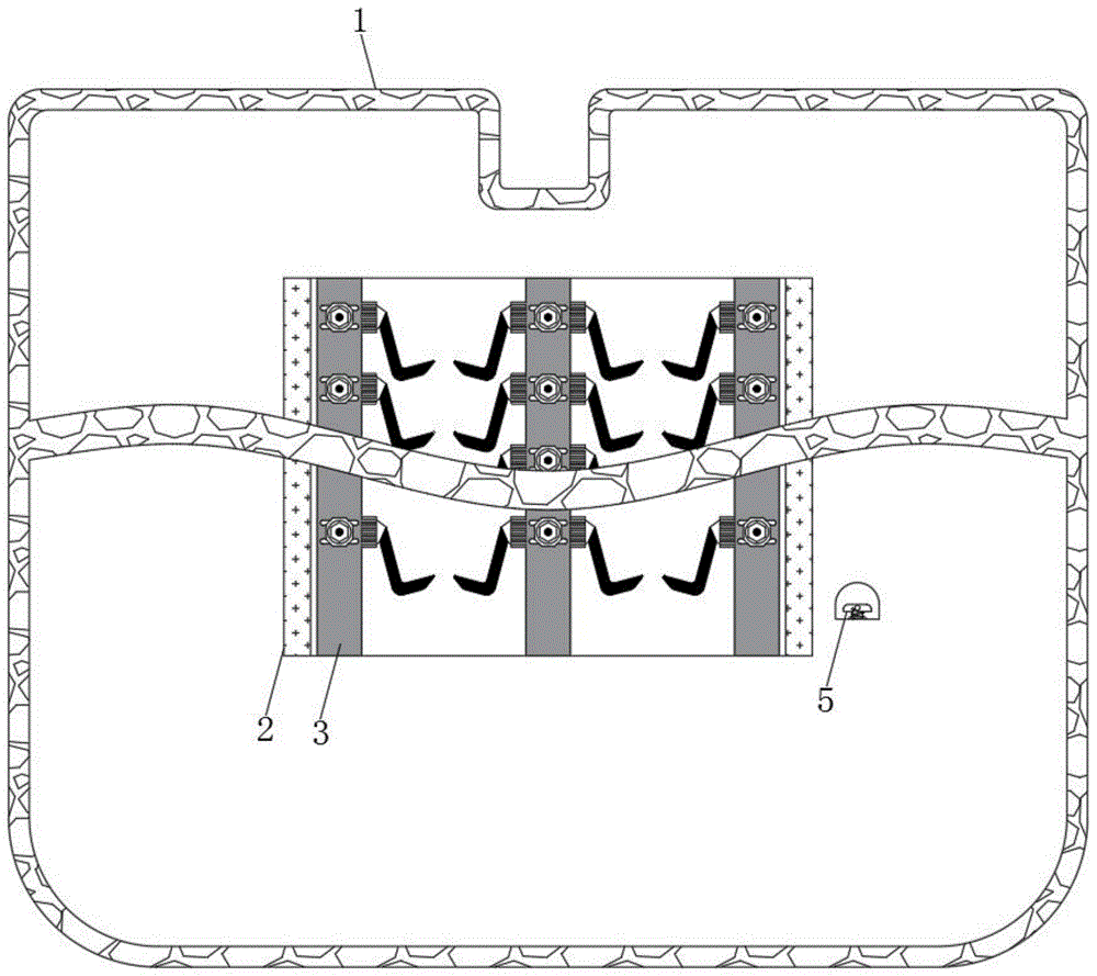
FIG. 1 is a schematic structural view of the present invention;
FIG. 2 is a cross-sectional view of FIG. 1 in accordance with the present invention;
FIG. 3 is an enlarged view of the structure of FIG. 2;
FIG. 4 is a schematic view of the turntable structure of the present invention.
In the figure: 1. a housing; 2. a sterilization chamber; 3. a rack; 4. a shutter; 5. a brake lever; 6. a rotating assembly; 7. a ratchet wheel; 8. turning the column; 9. a gear; 10. a socket; 11. a plug; 12. a movable rod; 13. a leaf of a snail; 14. spraying tools; 15. a current limiting frame; 16. a chuck; 17. a connecting rod; 18. a turntable.
Detailed Description
The technical solutions in the embodiments of the present invention will be clearly and completely described below with reference to the drawings in the embodiments of the present invention, and it is obvious that the described embodiments are only a part of the embodiments of the present invention, and not all of the embodiments. All other embodiments, which can be derived by a person skilled in the art from the embodiments given herein without making any creative effort, shall fall within the protection scope of the present invention.
Referring to fig. 1-4, a sterilizing device for nursing in an EICU intensive care unit comprises a shell 1, a sterilizing chamber 2 is fixedly connected inside the shell 1, a placing opening is formed in the surface of the sterilizing chamber 2, a clamping groove is formed in the surface of the inner wall of the sterilizing chamber 2, shielding plates 4 are movably connected in the clamping groove, a storage rack 3 is fixedly connected inside the sterilizing chamber 2, the number of the storage racks 3 is not less than three, a plurality of hooks and magnets are fixedly connected on the surface of the storage rack, medical devices can be conveniently hung and placed, shielding plates 4 are movably connected inside the sterilizing chamber 2, the shielding plates 4 are provided with two parts and have the same specification, connecting rods are fixedly connected on the outer sides of the shielding plates 4, a chain is movably connected on one side of each connecting rod, which is far away from the shielding plate 4, a gear 9 is movably connected inside the chain, a brake rod 5, spacing pipe fixed connection is on the surface of disinfection room 2, swing joint has the spring between 5 horizontal poles of spacing pipe and brake lever, the below swing joint of brake lever 5 has runner assembly 6, runner assembly 6 has the master, L type pole and side lever constitute, L type pole and side lever all have two and the same, one side that L type pole is close to 6 masters of runner assembly presents the arcuation, side lever fixed connection is in the outside of L type pole straight-bar, the surperficial swing joint of upper bar has the trace, the trace presents and inverts the Z form, wherein the outside swing joint of the middle part body of rod has the shell fragment.
The surface of the rotating component 6 is movably connected with a ratchet wheel 7, the lower part of the ratchet wheel 7 is movably connected with a rotating column 8, the surface of the rotating column 8 is provided with an X-shaped channel, the size of the X-shaped channel is matched with the size of a side lever of the rotating component 6, the surface of the rotating column 8 is provided with four notches with the same specification, every two notches are in one group, two notches of each group are positioned on the same straight line, the two groups of notches are symmetrically distributed by taking the central axis of the rotating column 8 as reference, the size of the notches is matched with the size of an L-shaped lever arc lever of the rotating component 6, the left side of the rotating column 8 is fixedly connected with a first cone pulley, the left side of the rotating column 8 is movably connected with a gear 9, the gears 9 are two and have the same specification, the surface of the right gear 9 is fixedly connected with a second cone pulley, the second cone pulley is meshed with the, The spiral shell leaf 13 is connected with carousel 18 electricity, and the below swing joint of socket 10 has plug 11, and plug 11's bottom fixedly connected with links the piece, and the surperficial swing joint that links the piece has two swing rods that the specification is the same, and one side and the movable rod 12 swing joint of linking the piece are kept away from to the swing rod, and the draw-in groove has been seted up on the outside that links the piece and the surface that is located 1 inner wall of shell, links the piece activity card and in its draw-in groove, has limiting displacement to plug 11's removal.
The outer side of the plug 11 is movably connected with a movable rod 12, the movable rod 12 is in an I shape, the outer side of a vertical rod is fixedly connected with a clamping column, the outer side of the vertical rod is movably connected with a spring, one side of the spring, which is far away from the movable rod 12, is fixedly connected with a groove plate, the surface of the groove plate is provided with two clamping grooves with the same specification, the size of the clamping grooves is matched with the size of the clamping column of the vertical rod of the movable rod 12, the upper part of the disinfection chamber 2 is movably connected with a screw blade 13, the outer side of the screw blade 13 is fixedly connected with a sprayer 14, the sprayer 14 is composed of a sprayer and a connecting pipe, the outer side of the connecting pipe is fixedly connected with a current-limiting frame 15, the pipe body of the connecting pipe, which is positioned in the limiting frame 15, is made of soft material, the outer side of the sprayer 14 is fixedly connected with a current-limiting frame, one side swing joint that chuck 16 was kept away from to connecting rod 17 has carousel 18, and logical groove has been seted up on the surface of carousel 18, and it leads to inslot swing joint to have interior pole, and the outside swing joint of interior pole has the spring, and one side swing joint that the spring was kept away from to interior pole has connecting rod 17, and one side fixedly connected with spacing collar plate of interior pole is kept away from to the spring, and spacing collar plate fixed connection is at the logical inslot of carousel 18, and carousel 18 keeps away from one side fixedly connected with arc pin of chuck 16.
The working process and the principle of the device are as follows:
when in use, the upper drawing moving rod 5 is released again, the brake rod 5 stretches the spring and is far away from the linkage rod on the surface of the side rod of the rotating component 6, the linkage rod does not obstruct the motion of the linkage rod any more, the linkage rod is limited by the elastic sheet, part of the rod body is movably clamped between the ratchets of the ratchet wheel 7, the ratchet wheel 7 drives the rotating component 6 to rotate through the linkage rod, two side rods and two L-shaped rods of the rotating component 6 are close to the rotating column 8 in sequence, the side rods move to one inclined groove of an X-shaped operating knife of the rotating column 8 and then are far away, the rotating column 8 is driven to rotate, the arc rod of the L-shaped rod moves to the notch of the rotating column 8 and then is far away, the rotating column 8 is stopped in time, the other side rod and the L-shaped rod of the subsequent rotating component 6 are close to the rotating column 8, the rotating column 8 is driven to rotate reversely and then are kept still, the rotating column 8 is caused, drive right side gear 9 and carry out intermittent type reciprocating motion, right side gear 9 drives left side gear 9 through the chain and rotates, and the chain carries out reciprocating motion and drives two sunshade 4 through the connecting rod and be close to each other and keep away from again, realizes that disinfection room 2 places the automatic switch of mouth, makes things convenient for going on of disinfection operation.
When the two shielding plates 4 shield the placing opening of the disinfection chamber 2, the two connecting rods on the surfaces of the chains push the movable rods 12 to move, so that the two movable rods 12 are far away from each other, the movable rods 12 pull the plug 11 to move upwards together with the connecting block at the bottom of the plug through the rotating rods, the plug 11 is close to the socket 10 and is clamped with the socket, and the screw blade 13 and the rotating disc 18 which are electrically connected with the socket rotate clockwise.
The rotary table 18 drives the inner rod in the clamping groove to move synchronously, the inner rod rotates to be close to the arc-shaped stop lever on the outer side of the rotary table 18, the movement of the inner rod is blocked, the inner rod extrudes a spring on the outer side of the inner rod, the inner rod drives the chuck 16 to move to the rightmost side along the clamping groove of the current-limiting frame 15 by pulling the connecting rod 17, the inner rod moves on the outer side of the arc-shaped stop lever at the moment, the connecting rod 17 is driven to rotate by taking the joint of the connecting rod 17 and the chuck 16 as a rotating point, the chuck 16 keeps in a static state, the chuck 16 does not extrude a connecting pipe of the sprayer 14 in the current-limiting frame any more, the ozone sprayer 14 moves in the inner disinfection chamber 2, the subsequent rotary table 18 drives the inner rod to be far away from the arc-shaped stop lever, the inner rod moves in the clamping groove of the rotary table 18 under the action of the spring, the connecting rod 17 pushes the connecting pipe close, so that the sterilizing liquid is uniformly distributed in the sterilizing chamber 2, thereby achieving the effect of comprehensively sterilizing the instruments on the object rack 3.
Although embodiments of the present invention have been shown and described, it will be appreciated by those skilled in the art that changes, modifications, substitutions and alterations can be made in these embodiments without departing from the principles and spirit of the invention, the scope of which is defined in the appended claims and their equivalents.