CN112493268B - Multi-functional mochi device - Google Patents
Multi-functional mochi device Download PDFInfo
- Publication number
- CN112493268B CN112493268B CN202011328001.0A CN202011328001A CN112493268B CN 112493268 B CN112493268 B CN 112493268B CN 202011328001 A CN202011328001 A CN 202011328001A CN 112493268 B CN112493268 B CN 112493268B
- Authority
- CN
- China
- Prior art keywords
- bevel gear
- rotating shaft
- driving wheel
- electric push
- push rod
- Prior art date
- Legal status (The legal status is an assumption and is not a legal conclusion. Google has not performed a legal analysis and makes no representation as to the accuracy of the status listed.)
- Active
Links
Images




Classifications
-
- A—HUMAN NECESSITIES
- A21—BAKING; EDIBLE DOUGHS
- A21C—MACHINES OR EQUIPMENT FOR MAKING OR PROCESSING DOUGHS; HANDLING BAKED ARTICLES MADE FROM DOUGH
- A21C1/00—Mixing or kneading machines for the preparation of dough
- A21C1/02—Mixing or kneading machines for the preparation of dough with vertically-mounted tools; Machines for whipping or beating
-
- A—HUMAN NECESSITIES
- A21—BAKING; EDIBLE DOUGHS
- A21C—MACHINES OR EQUIPMENT FOR MAKING OR PROCESSING DOUGHS; HANDLING BAKED ARTICLES MADE FROM DOUGH
- A21C1/00—Mixing or kneading machines for the preparation of dough
- A21C1/14—Structural elements of mixing or kneading machines; Parts; Accessories
-
- A—HUMAN NECESSITIES
- A21—BAKING; EDIBLE DOUGHS
- A21C—MACHINES OR EQUIPMENT FOR MAKING OR PROCESSING DOUGHS; HANDLING BAKED ARTICLES MADE FROM DOUGH
- A21C9/00—Other apparatus for handling dough or dough pieces
- A21C9/08—Depositing, arranging and conveying apparatus for handling pieces, e.g. sheets of dough
-
- Y—GENERAL TAGGING OF NEW TECHNOLOGICAL DEVELOPMENTS; GENERAL TAGGING OF CROSS-SECTIONAL TECHNOLOGIES SPANNING OVER SEVERAL SECTIONS OF THE IPC; TECHNICAL SUBJECTS COVERED BY FORMER USPC CROSS-REFERENCE ART COLLECTIONS [XRACs] AND DIGESTS
- Y02—TECHNOLOGIES OR APPLICATIONS FOR MITIGATION OR ADAPTATION AGAINST CLIMATE CHANGE
- Y02A—TECHNOLOGIES FOR ADAPTATION TO CLIMATE CHANGE
- Y02A40/00—Adaptation technologies in agriculture, forestry, livestock or agroalimentary production
- Y02A40/90—Adaptation technologies in agriculture, forestry, livestock or agroalimentary production in food processing or handling, e.g. food conservation
Landscapes
- Life Sciences & Earth Sciences (AREA)
- Engineering & Computer Science (AREA)
- Food Science & Technology (AREA)
- Transmission Devices (AREA)
Abstract
The invention relates to the field of food, in particular to a multifunctional mochi device. The technical problems to be solved by the invention are as follows: provides a multifunctional mochi device. The technical scheme is as follows: a multifunctional mochi device comprises wheels, a clamping system, a material taking system and the like; the clamping system is connected with the material taking system. The method is designed aiming at various eating methods of the mochi, combines the characteristics of elasticity and viscosity of the mochi, and jumps out of the conventional operation that an operator is required to continuously stir raw materials of the mochi in the manual processing in the processing process of the mochi, so that the selling process of the mochi can be completed by a single person; the mochi is sold in small portions, so that various ingredients can be added into one small portion of the mochi to achieve multiple tastes; the current situation that the mochi cannot be sold integrally from the manufacture in the prior art is changed.
Description
Technical Field
The invention relates to the field of food, in particular to a multifunctional mochi device.
Background
The mochi is a glutinous rice cake made of glutinous rice flour or other starch, and is an elastic and viscous food;
the mochi is eaten in various ways, and because the mochi is characterized by elasticity and viscosity, in the processing process of the mochi, manual processing requires an operator to continuously stir raw materials of the mochi, and single-person operation cannot be realized in the selling process of the mochi; in addition, the mochi selling process is to sell small parts, and various ingredients are added into the small part of the mochi to realize multiple tastes; the prior art can not find the device which can integrate the mochi production and the mochi selling.
Disclosure of Invention
In order to overcome the various eating methods of the mochi, the mochi is characterized by elasticity and viscosity, and the manual processing requires an operator to continuously stir raw materials of the mochi in the processing process of the mochi, so that the single-person operation can not be realized in the selling process of the mochi; in addition, the mochi selling process is to sell small parts, and various ingredients are added into the small part of the mochi to realize multiple tastes; the invention aims to solve the technical problems that in the prior art, a device which can integrate mochi production and mochi selling cannot be found: provides a multifunctional mochi device.
The technical scheme is as follows: a multifunctional mochi device comprises wheels, a supporting underframe, a controller, a raw material preparation system, a clamping system and a material taking system; the wheels are connected with the supporting underframe through bolts; the supporting underframe is connected with the controller; the supporting underframe is sequentially provided with a raw material preparation system, a clamping system and a material taking system; the raw material preparation system is connected with the clamping system; the clamping system is connected with the material taking system.
Preferably, the raw material preparation system comprises a hot water tank, a blanking box, a stirring box, a first bevel gear, a first rotating shaft, a first driving wheel, a second driving wheel, a stirrer, a heating block, an object bearing plate, a first electric push rod, a first slide rail, a second electric push rod, a second slide rail, a third driving wheel, a second rotating shaft, a second bevel gear, a third electric push rod, a third bevel gear, a fourth bevel gear, a first screw rod, a fourth driving wheel, a first rotating moving block, a fifth driving wheel, a second screw rod and a second rotating moving block; the hot water tank is welded with the supporting underframe; a blanking box is arranged on one side of the hot water tank; the blanking box is welded with the supporting underframe; one side of the blanking box is provided with a stirring box; the stirring box is connected with the object bearing plate; a plurality of groups of heating blocks are arranged on the outer ring surface of the stirring box; a first bevel gear is arranged on one side of the stirring box; the first bevel gear is connected with the clamping system; two ends of the first rotating shaft are fixedly connected with the first bevel gear and the first driving wheel respectively; the first rotating shaft is rotatably connected with the supporting underframe through a bracket; the outer ring surface of the first driving wheel is in transmission connection with the second driving wheel through a belt; the second driving wheel is fixedly connected with the stirrer; the stirrer is rotationally connected with the supporting underframe; two ends of the object bearing plate are respectively connected with the first electric push rod and the second electric push rod; the first electric push rod is connected with the first slide rail in a sliding manner; welding the first sliding rail and the supporting underframe; the second electric push rod is connected with the second slide rail in a sliding manner; welding the second slide rail with the supporting underframe; a third driving wheel is arranged above one side of the first sliding rail; the third driving wheel is connected with the clamping system; the second rotating shaft is fixedly connected with the third transmission wheel and the second bevel gear; the second rotating shaft is rotatably connected with the supporting underframe through a bracket; a third electric push rod is arranged on one side of the second bevel gear; the third electric push rod is connected with a third bevel gear through a shaft sleeve; a fourth bevel gear is arranged on one side of the third bevel gear; the first screw rod is fixedly connected with the fourth bevel gear and the fourth driving wheel in sequence; the first screw rod is connected with the first rotary moving block in a screwing way; the first screw rod is rotatably connected with the supporting underframe through a bracket; the outer ring surface of the fourth driving wheel is in transmission connection with the fifth driving wheel through a belt; the fifth driving wheel is fixedly connected with the second screw rod; the second screw rod is connected with the second rotary moving block in a screwing way; the second screw rod is rotatably connected with the supporting underframe through a bracket.
Preferably, the clamping system comprises a double-shaft motor, a first transmission shaft, a fifth bevel gear, a sixth bevel gear, a third rotating shaft, a sixth transmission wheel, a seventh bevel gear, a seventh transmission wheel, an eighth transmission wheel, a fourth rotating shaft, an eighth bevel gear, a ninth bevel gear, a third screw rod, a ninth transmission wheel, a third rotating moving block, a carrier frame, a tenth transmission wheel, a fourth screw rod, a fourth rotating moving block, a first sliding block, a second sliding block, a round rod, a first gear, a second gear, a fifth rotating shaft, a tenth bevel gear, a fourth electric push rod, an eleventh bevel gear, a twelfth bevel gear, a fifth screw rod, a second transmission shaft and a thirteenth bevel gear; the double-shaft motor is connected with the supporting underframe through bolts; two ends of the double-shaft motor are fixedly connected with the first transmission shaft and the second transmission shaft respectively; the first transmission shaft is fixedly connected with the fifth bevel gear; the first transmission shaft is rotatably connected with the supporting underframe through a bracket; the fifth bevel gear is meshed with the sixth bevel gear; the third rotating shaft is fixedly connected with a sixth bevel gear, a seventh driving wheel, a seventh bevel gear and a sixth driving wheel in sequence; the third rotating shaft is rotatably connected with the supporting underframe through a bracket; the outer ring surface of the sixth driving wheel is in transmission connection with the third driving wheel through a belt; the seventh bevel gear is meshed with the first bevel gear; the outer ring surface of the seventh driving wheel is in transmission connection with the eighth driving wheel through a belt; the fourth rotating shaft is fixedly connected with an eighth bevel gear, an eighth driving wheel and the first gear in sequence; the fourth rotating shaft is rotatably connected with the supporting underframe through a bracket; the eighth bevel gear is meshed with the ninth bevel gear; the third screw rod is fixedly connected with a ninth bevel gear and a ninth driving wheel in sequence; the third screw rod is rotationally connected with the third rotary moving block; the third screw rod is connected with the object carrier in a rotating way; the third screw rod is rotationally connected with the first slide block; the outer ring surface of the ninth driving wheel is in transmission connection with the tenth driving wheel through a belt; the tenth driving wheel is fixedly connected with the fourth screw rod; the fourth screw rod is in screwed connection with the object carrier; the fourth screw rod is rotationally connected with the fourth rotary moving block; the fourth screw rod is rotatably connected with the second sliding block; the round rod is sequentially connected with the first sliding block and the second sliding block in a sliding manner; the round rod is welded with the supporting underframe; the first gear is meshed with the second gear; the fifth rotating shaft is fixedly connected with the second gear and the tenth bevel gear in sequence; a fourth electric push rod is arranged on one side of the tenth bevel gear; the fourth electric push rod is connected with the eleventh bevel gear through a shaft sleeve; a twelfth bevel gear is arranged on one side of the eleventh bevel gear; the twelfth bevel gear is fixedly connected with the fifth screw rod; the fifth screw rod is rotatably connected with the supporting underframe through a bracket; the fifth screw rod is sequentially connected with the third rotary moving block and the fourth rotary moving block in a screwing mode; the second transmission shaft is fixedly connected with a thirteenth bevel gear; the second transmission shaft is rotatably connected with the supporting underframe through a bracket; and the thirteenth bevel gear is connected with the material taking system.
Preferably, the material taking system comprises a fourteenth bevel gear, a sixth rotating shaft, a cylindrical pin, a fifteenth bevel gear, a sixteenth bevel gear, a seventh rotating shaft, a worm, a turbine, an eighth rotating shaft, a seventeenth bevel gear, a fifth electric push rod, an eighteenth bevel gear, a nineteenth bevel gear, a ninth rotating shaft, a third gear, a first rack, a third sliding rail, a fourth gear, a second rack, a fourth sliding rail, a picking assembly, a grooved pulley, a tenth rotating shaft, an eleventh transmission wheel, a twelfth transmission wheel, an eleventh rotating shaft and a material conveyor; the fourteenth bevel gear is meshed with the thirteenth bevel gear; the sixth rotating shaft is fixedly connected with the fourteenth bevel gear, the cylindrical pin and the fifteenth bevel gear in sequence; the sixth rotating shaft is rotatably connected with the supporting underframe through a bracket; the cylindrical pin is connected with the grooved pulley; the fifteenth bevel gear is meshed with the sixteenth bevel gear; two ends of the seventh rotating shaft are fixedly connected with the sixteenth bevel gear and the worm respectively; the seventh rotating shaft is rotatably connected with the supporting underframe through a bracket; the worm is meshed with the turbine; the eighth rotating shaft is fixedly connected with the turbine and the seventeenth bevel gear in sequence; the eighth rotating shaft is rotatably connected with the supporting underframe; a fifth electric push rod is arranged on one side of the seventeenth bevel gear; the fifth electric push rod is connected with the eighteenth bevel gear through a shaft sleeve; a nineteenth bevel gear is arranged on one side of the eighteenth bevel gear; the ninth rotating shaft is fixedly connected with a nineteenth bevel gear, a third gear and a fourth gear in sequence; the ninth rotating shaft is rotatably connected with the supporting underframe through a bracket; the third gear is meshed with the first rack; the first rack is connected with the third slide rail in a sliding manner; the third sliding rail is welded with the supporting underframe; the fourth gear is meshed with the second rack; the second rack is in sliding connection with the fourth sliding rail; welding the fourth sliding rail with the supporting underframe; two ends of the picking assembly are respectively welded with the first rack and the second rack; the tenth rotating shaft is fixedly connected with the grooved wheel and the eleventh driving wheel in sequence; the tenth rotating shaft is rotatably connected with the supporting underframe through a bracket; the outer ring surface of the eleventh driving wheel is in transmission connection with the twelfth driving wheel through a belt; the twelfth driving wheel is fixedly connected with the eleventh rotating shaft; the eleventh rotating shaft is fixedly connected with the material conveyor; the eleventh rotating shaft is rotatably connected with the supporting underframe through a bracket; the material conveyor is connected with the supporting underframe in a sliding way.
Preferably, the picking assembly further comprises a first fixing plate, a sixth electric push rod, a seventh electric push rod, a second fixing plate, an eighth electric push rod, a first pushing device, a first clamping groove and a second clamping groove; two ends of the first fixing plate are respectively welded with the first rack and the second rack; two ends of the first fixing plate are respectively connected with the sixth electric push rod and the seventh electric push rod; two ends of the second fixing plate are respectively connected with the sixth electric push rod and the seventh electric push rod through bolts; the second fixing plate is connected with the eighth electric push rod through a bolt; the eighth electric push rod is connected with the first pusher; the first pushing device is connected with the second fixing plate in a sliding mode; two ends of the first pusher are respectively connected with the first clamping groove and the second clamping groove; the first clamping groove is rotationally connected with the second fixing plate; the second clamping groove is rotatably connected with the second fixing plate.
Preferably, the object bearing plate is provided with a bump at two ends thereof, and the first rotating moving block and the second rotating moving block are provided with grooves.
Preferably, the object carrying frame is provided with object carrying round frames with different inner diameters.
Preferably, four groups of blanking pipes are arranged on the material conveyor.
The invention has the beneficial effects that: the raw material preparation system is designed, the initial forming of the mochi is realized by stirring and continuously preserving heat of the mochi raw material, and the conveying of the mochi is completed;
the clamping system is designed, and the loading of the mochi is realized by carrying the paper cup type carrying box;
the invention designs a material taking system, the mochi is picked up and then released to a carrying box of paper cups, and seasoning conveying is carried out on the mochi in the carrying box through a blanking pipe, so that various eating methods of the mochi are realized;
the method is designed aiming at various eating methods of the mochi, combines the characteristics of elasticity and viscosity of the mochi, and jumps out of the conventional operation that an operator is required to continuously stir raw materials of the mochi in the manual processing in the processing process of the mochi, so that the selling process of the mochi can be completed by a single person; the mochi is sold in small portions, so that various ingredients can be added into one small portion of the mochi to achieve multiple tastes; the current situation that the mochi cannot be sold integrally from the manufacture in the prior art is changed.
Drawings
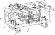
FIG. 1 is a schematic perspective view of a first embodiment of the present invention;
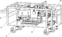
FIG. 2 is a schematic perspective view of a second embodiment of the present invention;
FIG. 3 is a schematic perspective view of a first embodiment of the feedstock preparation system of the present invention;
FIG. 4 is a schematic perspective view of a second feedstock preparation system according to the present invention;
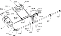
FIG. 5 is a schematic perspective view of a clamping system according to the present invention;
FIG. 6 is a schematic view of a first embodiment of a reclaiming system according to the present invention;
fig. 7 is a schematic perspective view of a second reclaiming system of the present invention.
Reference numerals: 1_ wheel, 2_ support chassis, 3_ controller, 4_ raw material preparation system, 5_ gripper system, 6_ reclaiming system, 401_ hot water tank, 402_ blanking box, 403_ stirring box, 404_ first bevel gear, 405_ first rotating shaft, 406_ first driving wheel, 407_ second driving wheel, 408_ stirrer, 409_ heating block, 4010_ object bearing plate, 4011_ first electric push rod, 4012_ first slide rail, 4013_ second electric push rod, 4014_ second slide rail, 4015_ third driving wheel, 4016_ second rotating shaft, 4017_ second bevel gear, 4018_ third electric push rod, 4019_ third bevel gear, 4020_ fourth bevel gear, 4021_ first driving wheel, 4022_ fourth driving wheel, 4023_ first rotating moving block, 4024_ fifth driving wheel, 4025_ second lead screw, 4026_ second rotating moving block, 4024_ double-shaft motor, 502_ first rotating shaft, 503_ first rotating shaft, 504_ sixth bevel gear, 505_ third shaft, 506_ sixth drive wheel, 507_ seventh bevel gear, 508_ seventh drive wheel, 509_ eighth drive wheel, 5010_ fourth shaft, 5011_ eighth bevel gear, 5012_ ninth bevel gear, 5013_ third screw, 5014_ ninth drive wheel, 5015_ third rotating moving block, 5016_ carrier, 5017_ tenth drive wheel, 5018_ fourth screw, 5019_ fourth rotating moving block, 5020_ first slider, 5021_ second slider, 5022_ round bar, 5023_ first gear, 5024_ second gear, 5025_ fifth shaft, 5026_ tenth bevel gear, 5027_ fourth electric push rod, 5028_ eleventh bevel gear, 5029_ twelfth bevel gear, 5030_ fifth screw, 5031_ second drive shaft, 5022_ thirteenth, 601_ fourteenth bevel gear, 602_ sixth shaft, 603_ pin, 605_ fifteenth shaft, 604_ sixteenth bevel gear, 606_ seventh rotating shaft, 607_ worm, 608_ worm wheel, 609_ eighth rotating shaft, 6010_ seventeenth bevel gear, 6011_ fifth electric push rod, 6012_ eighteenth bevel gear, 6013_ nineteenth bevel gear, 6014_ ninth rotating shaft, 6015_ third gear, 6016_ first rack, 6017_ third slide rail, 6018_ fourth gear, 6019_ second rack, 6020_ fourth slide rail, 6021_ pickup assembly, 602101_ first fixing plate, 602102_ sixth electric push rod, 602103_ seventh electric push rod, 602104_ second fixing plate, 602105_ eighth electric push rod, 602106_ first pusher, 602107_ first clamping groove, 602108_ second clamping groove, 6022_ sheave, 6023_ tenth rotating shaft, 6024_ eleventh driving wheel, 6025_ twelfth driving wheel, 6026_ eleventh rotating shaft, 6027_ material conveyor.
Detailed Description
The invention is further described below with reference to the figures and examples.
Example 1
A multifunctional sweet potato device is shown in figures 1-7 and comprises wheels 1, a supporting chassis 2, a controller 3, a raw material preparation system 4, a clamping system 5 and a material taking system 6; the wheel 1 is connected with the supporting underframe 2 through bolts; the supporting underframe 2 is connected with the controller 3; the supporting underframe 2 is sequentially provided with a raw material preparation system 4, a clamping system 5 and a material taking system 6; the raw material preparation system 4 is connected with the clamping system 5; the clamping system 5 is connected with the material taking system 6.
The working principle is as follows: before the device works, the whole device is pushed to a mochi selling point by using the wheels 1, then the power supply is switched on, the controller 3 is controlled to start the device, the running transmission condition among all systems is checked, and the device is closed after the error is confirmed; preparing a mochi raw material, controlling the controller 3 to start the device again, and enabling the clamping system 5 to run on the supporting underframe 2 to be responsible for power transmission of the whole device; the clamping system 5 drives the raw material preparation system 4 to stir and continuously preserve heat of the mochi raw material, so that the initial forming of the mochi is realized, and the mochi conveying is completed; the clamping system 5 is used for loading the mochi by carrying a paper cup type carrying box; the clamping system 5 is used for driving the material taking system 6, picking the mochi and then releasing the mochi to a carrying box of paper cups, and then conveying seasonings to the mochi in the carrying box through a blanking pipe, so that various eating methods of the mochi are realized; the method is designed aiming at various eating methods of the mochi, combines the characteristics of elasticity and viscosity of the mochi, and jumps out of the conventional operation that an operator is required to continuously stir raw materials of the mochi in the manual processing in the processing process of the mochi, so that the selling process of the mochi can be completed by a single person; the mochi is sold in small portions, so that various ingredients can be added into one small portion of the mochi to achieve multiple tastes; the current situation that the mochi cannot be sold integrally from the manufacture in the prior art is changed.
The raw material preparation system 4 comprises a hot water tank 401, a blanking box 402, a stirring box 403, a first bevel gear 404, a first rotating shaft 405, a first driving wheel 406, a second driving wheel 407, a stirrer 408, a heating block 409, a bearing plate 4010, a first electric push rod 4011, a first sliding rail 4012, a second electric push rod 4013, a second sliding rail 4014, a third driving wheel 4015, a second rotating shaft 4016, a second bevel gear 4017, a third electric push rod 4018, a third bevel gear 4019, a fourth bevel gear 4020, a first screw 4021, a fourth driving wheel 4022, a first rotating moving block 4023, a fifth driving wheel 4024, a second screw 4025 and a second rotating moving block 4026; the hot water tank 401 is welded with the support chassis 2; a blanking box 402 is arranged on one side of the hot water tank 401; the blanking box 402 is welded to the support chassis 2; one side of the blanking box 402 is provided with a stirring box 403; the stirring box 403 is connected with an object bearing plate 4010; a plurality of groups of heating blocks 409 are arranged on the outer circumferential surface of the stirring box 403; a first bevel gear 404 is arranged on one side of the stirring box 403; the first bevel gear 404 is connected with the clamping system 5; two ends of the first rotating shaft 405 are fixedly connected with the first bevel gear 404 and the first driving wheel 406 respectively; the first rotating shaft 405 is rotatably connected with the supporting chassis 2 through a bracket; the outer ring surface of the first driving wheel 406 is in transmission connection with a second driving wheel 407 through a belt; the second driving wheel 407 is fixedly connected with the stirrer 408; the stirrer 408 is rotatably connected to the support chassis 2; two ends of the object bearing plate 4010 are respectively connected with a first electric push rod 4011 and a second electric push rod 4013; the first electric push rod 4011 is in sliding connection with the first slide rail 4012; the first sliding rail 4012 is welded with the support chassis 2; the second electric push rod 4013 is connected with the second slide rail 4014 in a sliding way; the second slide rail 4014 is welded with the support chassis 2; a third driving wheel 4015 is arranged above one side of the first slide rail 4012; the third driving wheel 4015 is connected with the clamping system 5; the second rotating shaft 4016 is fixedly connected with a third driving wheel 4015 and a second bevel gear 4017; the second rotating shaft 4016 is rotatably connected with the supporting underframe 2 through a bracket; a third electric push rod 4018 is arranged on one side of the second bevel gear 4017; the third electric push rod 4018 is connected with a third bevel gear 4019 through a shaft sleeve; a fourth bevel gear 4020 is arranged on one side of the third bevel gear 4019; the first screw 4021 is fixedly connected with a fourth bevel gear 4020 and a fourth driving wheel 4022 in sequence; the first screw 4021 is screwed with the first rotary moving block 4023; the first screw 4021 is rotatably connected with the support chassis 2 through a bracket; the outer ring surface of the fourth driving wheel 4022 is in transmission connection with a fifth driving wheel 4024 through a belt; the fifth driving wheel 4024 is fixedly connected with the second screw 4025; the second screw 4025 is screwed with a second rotary moving block 4026; the second screw 4025 is rotatably connected to the support chassis 2 through a bracket.
The hot water tank 401 heats water and conveys the water to the stirring box 403, the raw materials of the mochi fed into the blanking box 402 enter the stirring box 403, and the clamping system 5 drives the first bevel gear 404 to realize power transmission between systems; the first bevel gear 404 drives the first rotating shaft 405 to rotate to drive the first driving wheel 406, the first driving wheel 406 drives the second driving wheel 407 to drive the stirrer 408 to rotate, the mochi raw material is continuously stirred, and the mochi is thickened; the heating block 409 is used for preserving heat of the stirring box 403, and after mochi production is completed, the first electric push rod 4011 and the second electric push rod 4013 simultaneously pull the object bearing plate 4010 welded with the stirring box 403 to move downwards; after the object bearing plate 4010 is embedded and combined with the first rotating moving block 4023 and the second rotating moving block 4026, the clamping system 5 drives the third driving wheel 4015 to drive the second rotating shaft 4016 to rotate, so that power transmission between the systems is realized; the second rotating shaft 4016 drives the second bevel gear 4017 to rotate all the time, and then the third electric push rod 4018 pushes the third bevel gear 4019 to be meshed with the second bevel gear 4017 and the fourth bevel gear 4020 respectively, so that the fourth bevel gear 4020 rotates and stops; the fourth bevel gear 4020 drives the first screw 4021 to rotate and transmit the fourth driving wheel 4022, and the fourth driving wheel 4022 transmits the fifth driving wheel 4024 to drive the second screw 4025 to rotate; the first screw rod 4021 and the second screw rod 4025 rotate and simultaneously drive the first rotating moving block 4023 and the second rotating moving block 4026 to move respectively, and due to the fact that the object bearing plate 4010 is embedded with the first rotating moving block 4023 and the second rotating moving block 4026, the first electric push rod 4011 starts to slide on the first slide rail 4012, and in the same way, the second electric push rod 4013 starts to slide on the second slide rail 4014; so as to convey the mochi in the stirring box 403; after the next working point is reached, the third electric push rod 4018 pulls the third bevel gear 4019 to be not meshed with the second bevel gear 4017 and the fourth bevel gear 4020, so that the stirring box 403 is static to cooperate with the next operation; this system realizes the preliminary shaping of mochi through stirring and constantly keeping warm the mochi raw materials to accomplish the transport of mochi.
The clamping system 5 comprises a double-shaft motor 501, a first transmission shaft 502, a fifth bevel gear 503, a sixth bevel gear 504, a third rotating shaft 505, a sixth transmission wheel 506, a seventh bevel gear 507, a seventh transmission wheel 508, an eighth transmission wheel 509, a fourth rotating shaft 5010, an eighth bevel gear 5011, a ninth bevel gear 5012, a third lead screw 5013, a ninth transmission wheel 5014, a third rotating moving block 5015, a carrier rack 5016, a tenth transmission wheel 5017, a fourth lead screw 5018, a fourth rotating moving block 5019, a first slider 5020, a second slider 5021, a round rod 5022, a first gear 5023, a second gear 5024, a fifth rotating shaft 5025, a tenth bevel gear 5026, a fourth electric push rod 7, an eleventh bevel gear 5028, a twelfth bevel gear 5029, a fifth lead screw 5030, a second transmission shaft 5031 and a thirteenth bevel gear 5032; the double-shaft motor 501 is connected with the support chassis 2 through bolts; two ends of the double-shaft motor 501 are fixedly connected with the first transmission shaft 502 and the second transmission shaft 5031 respectively; the first transmission shaft 502 is fixedly connected with a fifth bevel gear 503; the first transmission shaft 502 is rotatably connected with the support chassis 2 through a bracket; the fifth bevel gear 503 is meshed with the sixth bevel gear 504; the third rotating shaft 505 is fixedly connected with a sixth bevel gear 504, a seventh driving wheel 508, a seventh bevel gear 507 and a sixth driving wheel 506 in sequence; the third rotating shaft 505 is rotatably connected with the supporting underframe 2 through a bracket; the outer annular surface of the sixth driving wheel 506 is in driving connection with a third driving wheel 4015 through a belt; the seventh bevel gear 507 is engaged with the first bevel gear 404; the outer annular surface of the seventh transmission wheel 508 is in transmission connection with an eighth transmission wheel 509 through a belt; the fourth rotating shaft 5010 is fixedly connected with an eighth bevel gear 5011, an eighth driving wheel 509 and a first gear 5023 in sequence; the fourth rotating shaft 5010 is rotatably connected with the support chassis 2 through a bracket; the eighth bevel gear 5011 is engaged with the ninth bevel gear 5012; the third lead screw 5013 is fixedly connected with a ninth bevel gear 5012 and a ninth transmission wheel 5014 in sequence; the third lead screw 5013 is in rotational connection with a third rotating moving block 5015; the third screw 5013 is in screwed connection with the object carrier 5016; the third lead screw 5013 is in rotational connection with the first slider 5020; the outer ring surface of the ninth driving wheel 5014 is in transmission connection with a tenth driving wheel 5017 through a belt; the tenth transmission wheel 5017 is fixedly connected with a fourth screw 5018; the fourth screw 5018 is in screwed connection with the object carrier 5016; the fourth lead screw 5018 is rotatably connected with a fourth rotating moving block 5019; the fourth lead screw 5018 is in rotary connection with the second slider 5021; the round bar 5022 is in sliding connection with the first slider 5020 and the second slider 5021 in sequence; the round rod 5022 is welded with the support chassis 2; the first gear 5023 is engaged with the second gear 5024; the fifth rotating shaft 5025 is fixedly connected with a second gear 5024 and a tenth bevel gear 5026 in sequence; a fourth electric push rod 5027 is arranged on one side of the tenth bevel gear 5026; the fourth electric push rod 5027 is connected with an eleventh bevel gear 5028 through a shaft sleeve; a twelfth bevel gear 5029 is arranged on one side of the eleventh bevel gear 5028; a twelfth bevel gear 5029 is fixedly connected with the fifth lead screw 5030; the fifth lead screw 5030 is rotatably connected with the support chassis 2 through a bracket; the fifth lead screw 5030 is screwed with the third rotating moving block 5015 and the fourth rotating moving block 5019 in sequence; the second transmission shaft 5031 is fixedly connected with a thirteenth bevel gear 5032; the second transmission shaft 5031 is rotatably connected with the support chassis 2 through a bracket; the thirteenth bevel gear 5032 is connected to the take off system 6.
When the stirring box 403 reaches a working position, the double-shaft motor 501 drives the first transmission shaft 502 to drive the fifth bevel gear 503 to rotate, the fifth bevel gear 503 is meshed with the sixth bevel gear 504 to drive the third rotating shaft 505 to rotate, the third rotating shaft 505 drives the seventh transmission wheel 508, the seventh bevel gear 507 and the sixth transmission wheel 506 to rotate, and the sixth transmission wheel 506 drives the third transmission wheel 4015 to realize power transmission between systems; the seventh bevel gear 507 is meshed with the first bevel gear 404, so that power transmission among systems is realized; the seventh driving wheel 508 drives the eighth driving wheel 509 to drive the fourth rotating shaft 5010 to rotate, the fourth rotating shaft 5010 drives the eighth bevel gear 5011 to be meshed with the ninth bevel gear 5012, the ninth bevel gear 5012 drives the third screw 5013 to rotate and drive the ninth driving wheel 5014, the ninth driving wheel 5014 drives the tenth driving wheel 5017 to drive the fourth screw 5018 to rotate, the carrier 5016 moves while the third screw 5013 and the fourth screw 5018 rotate, and then a person manually places the paper cup type carrier on the carrier 5016; the double-shaft motor 501 drives the first transmission shaft 502 to rotate reversely, so that the object carrier 5016 returns to the position where the mochi falls; then, the fourth rotating shaft 5010 drives the first gear 5023 to engage with the second gear 5024, the second gear 5024 drives the fifth rotating shaft 5025 to drive the tenth bevel gear 5026, and the fourth electric push rod 5027 pushes the eleventh bevel gear 5028 to engage with the tenth bevel gear 5026 and the twelfth bevel gear 5029 respectively, so that the rotation and the stop of the twelfth bevel gear 5029 are realized; the twelfth bevel gear 5029 drives the fifth lead screw 5030 to rotate, so that the third rotating moving block 5015 and the fourth rotating moving block 5019 start to move to drive the ninth bevel gear 5012 not to be meshed with the eighth bevel gear 5011; then, a fourth electric push rod 5027 pulls an eleventh bevel gear 5028 to be not meshed with a tenth bevel gear 5026 and a twelfth bevel gear 5029, so that the object carrier 5016 does not move any more, after the mochi is loaded, the fourth electric push rod 5027 pushes the eleventh bevel gear 5028 to be respectively meshed with the tenth bevel gear 5026 and the twelfth bevel gear 5029, and meanwhile, a first slider 5020 and a second slider 5021 slide on a round rod 5022 to drive the object carrier 5016 to be positioned below a material conveyor 6027 of the material taking system 6; then, a fourth electric push rod 5027 pulls an eleventh bevel gear 5028 to be not meshed with a tenth bevel gear 5026 and a twelfth bevel gear 5029, so that the material bearing of the object carrier 5016 is realized; the double-shaft motor 501 drives the second transmission shaft 5031 to drive the thirteenth bevel gear 5032 to transmit the material taking system 6, so that power transmission between the systems is realized; this system bears through the thing box that carries to the paper cup class, realizes the loading to mochi.
The material taking system 6 comprises a fourteenth bevel gear 601, a sixth rotating shaft 602, a cylindrical pin 603, a fifteenth bevel gear 604, a sixteenth bevel gear 605, a seventh rotating shaft 606, a worm 607, a turbine 608, an eighth rotating shaft 609, a seventeenth bevel gear 6010, a fifth electric push rod 6011, an eighteenth bevel gear 6012, a nineteenth bevel gear 6013, a ninth rotating shaft 6014, a third gear 6015, a first rack 6016, a third slide rail 6017, a fourth gear 6018, a second rack 6019, a fourth slide rail 6020, a picking assembly 6021, a grooved pulley 6022, a tenth rotating shaft 6023, an eleventh driving wheel 6024, a twelfth driving wheel 6025, an eleventh rotating shaft 6026 and a material conveyor 6027; the fourteenth bevel gear 601 is meshed with the thirteenth bevel gear 5032; the sixth rotating shaft 602 is fixedly connected with a fourteenth bevel gear 601, a cylindrical pin 603 and a fifteenth bevel gear 604 in sequence; the sixth rotating shaft 602 is rotatably connected with the supporting chassis 2 through a bracket; the cylindrical pin 603 is connected with the grooved wheel 6022; the fifteenth bevel gear 604 meshes with the sixteenth bevel gear 605; two ends of the seventh rotating shaft 606 are fixedly connected with a sixteenth bevel gear 605 and a worm 607 respectively; the seventh rotating shaft 606 is rotatably connected with the supporting chassis 2 through a bracket; the worm 607 meshes with the worm wheel 608; the eighth rotating shaft 609 is fixedly connected with the turbine 608 and a seventeenth bevel gear 6010 in sequence; the eighth rotating shaft 609 is rotatably connected with the supporting underframe 2; a fifth electric push rod 6011 is arranged at one side of the seventeenth bevel gear 6010; the fifth electric push rod 6011 is connected with an eighteenth bevel gear 6012 through a shaft sleeve; a nineteenth bevel gear 6013 is arranged on one side of the eighteenth bevel gear 6012; the ninth rotating shaft 6014 is fixedly connected with a nineteenth bevel gear 6013, a third gear 6015 and a fourth gear 6018 in sequence; the ninth rotating shaft 6014 is rotatably connected with the supporting base frame 2 through a bracket; the third gear 6015 is engaged with the first rack 6016; the first rack 6016 is slidably connected to the third slide rail 6017; the third slide rail 6017 is welded with the support chassis 2; the fourth gear 6018 meshes with the second rack 6019; the second rack 6019 is slidably connected to the fourth slide rail 6020; the fourth slide rail 6020 is welded with the support chassis 2; the two ends of the picking assembly 6021 are respectively welded with the first rack 6016 and the second rack 6019; the tenth rotating shaft 6023 is fixedly connected with the grooved wheel 6022 and the eleventh driving wheel 6024 in sequence; the tenth rotating shaft 6023 is rotatably connected with the supporting chassis 2 through a bracket; the outer ring surface of the eleventh driving wheel 6024 is in transmission connection with the twelfth driving wheel 6025 through a belt; the twelfth driving wheel 6025 is fixedly connected with the eleventh rotating shaft 6026; the eleventh rotating shaft 6026 is fixedly connected with the material conveyer 6027; the eleventh rotating shaft 6026 is rotatably connected with the supporting chassis 2 through a bracket; feeder 6027 is slidably coupled to support chassis 2.
The picking assembly 6021 further comprises a first fixing plate 602101, a sixth electric push rod 602102, a seventh electric push rod 602103, a second fixing plate 602104, an eighth electric push rod 602105, a first pusher 602106, a first clamping groove 602107 and a second clamping groove 602108; two ends of the first fixing plate 602101 are respectively welded with the first rack 6016 and the second rack 6019; two ends of the first fixing plate 602101 are respectively connected with the sixth electric push rod 602102 and the seventh electric push rod 602103; two ends of the second fixing plate 602104 are respectively connected with the sixth electric push rod 602102 and the seventh electric push rod 602103 through bolts; the second fixing plate 602104 is connected with the eighth electric push rod 602105 through bolts; the eighth electric push rod 602105 is connected with the first pusher 602106; the first pusher 602106 is slidably connected with the second fixing plate 602104; the two ends of the first pusher 602106 are respectively connected with the first clamping groove 602107 and the second clamping groove 602108; the first clamping groove 602107 is rotatably connected with the second fixing plate 602104; the second clip groove 602108 is rotatably connected to the second fixing plate 602104.
The pick-up assembly 6021 operates by operating the sixth electric push rod 602102 and the seventh electric push rod 602103 connected to the first fixing plate 602101 to push the second fixing plate 602104 to a position where the first clamping groove 602107 and the second clamping groove 602108 can contact with the mochi, and then the eighth electric push rod 602105 pushes the first pusher 602106 to pull the first clamping groove 602107 and the second clamping groove 602108 to close tightly, so that the first pusher 602106 slides on the second fixing plate 602104 and can rotate at a certain angle on the first clamping groove 602107 and the second clamping groove 602108 to pick up the mochi.
The two ends of the object bearing plate 4010 are provided with bumps, and the first rotating moving block 4023 and the second rotating moving block 4026 are provided with grooves.
The projections at the two ends of the object bearing plate 4010 are matched with the grooves in the first rotating moving block 4023 and the second rotating moving block 4026, so that the stirring box 403 can be conveyed.
The object carrying frame 5016 is provided with an object carrying circular frame with different inner diameters.
The bearing of the paper cup carrying boxes with different sizes can be realized.
Four groups of blanking pipes are arranged on the material conveyor 6027.
Realize the delivery of various seasonings.
The above embodiments are merely illustrative of the technical ideas and features of the present invention, and the purpose thereof is to enable those skilled in the art to understand the contents of the present invention and implement the present invention, and not to limit the protection scope of the present invention. All equivalent changes and modifications made according to the spirit of the present invention should be covered within the protection scope of the present invention.
Claims (6)
1. A multifunctional sweet potato device comprises wheels, a supporting chassis and a controller; the device is characterized by also comprising a raw material preparation system, a clamping system and a material taking system; the wheels are connected with the supporting underframe through bolts; the supporting underframe is connected with the controller; the supporting underframe is sequentially provided with a raw material preparation system, a clamping system and a material taking system; the raw material preparation system is connected with the clamping system; the clamping system is connected with the material taking system;
the raw material preparation system comprises a hot water tank, a blanking box, a stirring box, a first bevel gear, a first rotating shaft, a first driving wheel, a second driving wheel, a stirrer, a heating block, a bearing plate, a first electric push rod, a first slide rail, a second electric push rod, a second slide rail, a third driving wheel, a second rotating shaft, a second bevel gear, a third electric push rod, a third bevel gear, a fourth bevel gear, a first screw rod, a fourth driving wheel, a first rotating moving block, a fifth driving wheel, a second screw rod and a second rotating moving block; the hot water tank is welded with the supporting underframe; a blanking box is arranged on one side of the hot water tank; the blanking box is welded with the supporting underframe; a stirring box is arranged on one side of the blanking box; the stirring box is connected with the object bearing plate; a plurality of groups of heating blocks are arranged on the outer ring surface of the stirring box; a first bevel gear is arranged on one side of the stirring box; the first bevel gear is connected with the clamping system; two ends of the first rotating shaft are fixedly connected with the first bevel gear and the first driving wheel respectively; the first rotating shaft is rotatably connected with the supporting underframe through a bracket; the outer ring surface of the first driving wheel is in transmission connection with the second driving wheel through a belt; the second driving wheel is fixedly connected with the stirrer; the stirrer is rotationally connected with the supporting underframe; two ends of the object bearing plate are respectively connected with the first electric push rod and the second electric push rod; the first electric push rod is connected with the first slide rail in a sliding manner; welding the first sliding rail and the supporting underframe; the second electric push rod is connected with the second slide rail in a sliding manner; welding the second slide rail with the supporting underframe; a third driving wheel is arranged above one side of the first sliding rail; the third driving wheel is connected with the clamping system; the second rotating shaft is fixedly connected with the third driving wheel and the second bevel gear; the second rotating shaft is rotatably connected with the supporting underframe through a bracket; a third electric push rod is arranged on one side of the second bevel gear; the third electric push rod is connected with a third bevel gear through a shaft sleeve; a fourth bevel gear is arranged on one side of the third bevel gear; the first screw rod is fixedly connected with a fourth bevel gear and a fourth driving wheel in sequence; the first screw rod is connected with the first rotary moving block in a screwing way; the first screw rod is rotationally connected with the supporting underframe through a bracket; the outer ring surface of the fourth driving wheel is in transmission connection with the fifth driving wheel through a belt; the fifth driving wheel is fixedly connected with the second screw rod; the second screw rod is connected with the second rotary moving block in a screwing way; the second screw rod is rotatably connected with the supporting underframe through a bracket;
the clamping system comprises a double-shaft motor, a first transmission shaft, a fifth bevel gear, a sixth bevel gear, a third rotating shaft, a sixth transmission wheel, a seventh bevel gear, a seventh transmission wheel, an eighth transmission wheel, a fourth rotating shaft, an eighth bevel gear, a ninth bevel gear, a third screw rod, a ninth transmission wheel, a third rotating moving block, a carrier, a tenth transmission wheel, a fourth screw rod, a fourth rotating moving block, a first sliding block, a second sliding block, a round rod, a first gear, a second gear, a fifth rotating shaft, a tenth bevel gear, a fourth electric push rod, an eleventh bevel gear, a twelfth bevel gear, a fifth screw rod, a second transmission shaft and a thirteenth bevel gear; the double-shaft motor is connected with the supporting underframe through bolts; two ends of the double-shaft motor are fixedly connected with the first transmission shaft and the second transmission shaft respectively; the first transmission shaft is fixedly connected with the fifth bevel gear; the first transmission shaft is rotatably connected with the supporting underframe through a bracket; the fifth bevel gear is meshed with the sixth bevel gear; the third rotating shaft is fixedly connected with a sixth bevel gear, a seventh driving wheel, a seventh bevel gear and a sixth driving wheel in sequence; the third rotating shaft is rotatably connected with the supporting underframe through a bracket; the outer ring surface of the sixth driving wheel is in transmission connection with the third driving wheel through a belt; the seventh bevel gear is meshed with the first bevel gear; the outer ring surface of the seventh driving wheel is in transmission connection with the eighth driving wheel through a belt; the fourth rotating shaft is fixedly connected with an eighth bevel gear, an eighth driving wheel and the first gear in sequence; the fourth rotating shaft is rotatably connected with the supporting underframe through a bracket; the eighth bevel gear is meshed with the ninth bevel gear; the third screw rod is fixedly connected with a ninth bevel gear and a ninth driving wheel in sequence; the third screw rod is rotationally connected with a third rotary moving block; the third screw rod is connected with the object carrier in a screwing way; the third screw rod is rotationally connected with the first slide block; the outer ring surface of the ninth driving wheel is in transmission connection with the tenth driving wheel through a belt; the tenth driving wheel is fixedly connected with the fourth screw rod; the fourth screw rod is connected with the object carrier in a rotating mode; the fourth screw rod is rotationally connected with the fourth rotary moving block; the fourth screw rod is rotationally connected with the second sliding block; the round rod is sequentially connected with the first sliding block and the second sliding block in a sliding manner; the round rod is welded with the supporting underframe; the first gear is meshed with the second gear; the fifth rotating shaft is fixedly connected with the second gear and the tenth bevel gear in sequence; a fourth electric push rod is arranged on one side of the tenth bevel gear; the fourth electric push rod is connected with the eleventh bevel gear through a shaft sleeve; a twelfth bevel gear is arranged on one side of the eleventh bevel gear; the twelfth bevel gear is fixedly connected with the fifth screw rod; the fifth screw rod is rotatably connected with the supporting underframe through a bracket; the fifth screw rod is sequentially connected with the third rotary moving block and the fourth rotary moving block in a screwing mode; the second transmission shaft is fixedly connected with a thirteenth bevel gear; the second transmission shaft is rotatably connected with the supporting underframe through a bracket; and the thirteenth bevel gear is connected with the material taking system.
2. The multifunctional mochi device according to claim 1, wherein the material taking system comprises a fourteenth bevel gear, a sixth rotating shaft, a cylindrical pin, a fifteenth bevel gear, a sixteenth bevel gear, a seventh rotating shaft, a worm screw, a worm wheel, an eighth rotating shaft, a seventeenth bevel gear, a fifth electric push rod, an eighteenth bevel gear, a nineteenth bevel gear, a ninth rotating shaft, a third gear, a first rack, a third slide rail, a fourth gear, a second rack, a fourth slide rail, a picking assembly, a grooved wheel, a tenth rotating shaft, an eleventh driving wheel, a twelfth driving wheel, an eleventh rotating shaft and a material conveyor; the fourteenth bevel gear is meshed with the thirteenth bevel gear; the sixth rotating shaft is fixedly connected with the fourteenth bevel gear, the cylindrical pin and the fifteenth bevel gear in sequence; the sixth rotating shaft is rotatably connected with the supporting underframe through a bracket; the cylindrical pin is connected with the grooved pulley; the fifteenth bevel gear is meshed with the sixteenth bevel gear; two ends of the seventh rotating shaft are fixedly connected with the sixteenth bevel gear and the worm respectively; the seventh rotating shaft is rotatably connected with the supporting underframe through a bracket; the worm is meshed with the worm wheel; the eighth rotating shaft is fixedly connected with the turbine and the seventeenth bevel gear in sequence; the eighth rotating shaft is rotatably connected with the supporting underframe; a fifth electric push rod is arranged on one side of the seventeenth bevel gear; the fifth electric push rod is connected with the eighteenth bevel gear through a shaft sleeve; a nineteenth bevel gear is arranged on one side of the eighteenth bevel gear; the ninth rotating shaft is fixedly connected with a nineteenth bevel gear, a third gear and a fourth gear in sequence; the ninth rotating shaft is rotatably connected with the supporting underframe through a bracket; the third gear is meshed with the first rack; the first rack is connected with the third slide rail in a sliding manner; the third sliding rail is welded with the supporting underframe; the fourth gear is meshed with the second rack; the second rack is in sliding connection with the fourth sliding rail; welding the fourth sliding rail with the supporting underframe; two ends of the picking assembly are respectively welded with the first rack and the second rack; the tenth rotating shaft is fixedly connected with the grooved pulley and the eleventh driving wheel in sequence; the tenth rotating shaft is rotatably connected with the supporting underframe through a bracket; the outer ring surface of the eleventh driving wheel is in transmission connection with the twelfth driving wheel through a belt; the twelfth driving wheel is fixedly connected with the eleventh rotating shaft; the eleventh rotating shaft is fixedly connected with the material conveyor; the eleventh rotating shaft is rotatably connected with the supporting underframe through a bracket; the material conveyor is connected with the supporting bottom frame in a sliding mode.
3. The multifunctional mochi device as claimed in claim 2, wherein the picking assembly further comprises a first fixing plate, a sixth electric pushing rod, a seventh electric pushing rod, a second fixing plate, an eighth electric pushing rod, a first pushing device, a first clamping groove and a second clamping groove; two ends of the first fixing plate are respectively welded with the first rack and the second rack; two ends of the first fixing plate are respectively connected with the sixth electric push rod and the seventh electric push rod; two ends of the second fixing plate are respectively connected with the sixth electric push rod and the seventh electric push rod through bolts; the second fixing plate is connected with the eighth electric push rod through a bolt; the eighth electric push rod is connected with the first pusher; the first pushing device is connected with the second fixing plate in a sliding mode; two ends of the first pusher are respectively connected with the first clamping groove and the second clamping groove; the first clamping groove is rotationally connected with the second fixing plate; the second clamping groove is rotatably connected with the second fixing plate.
4. The multifunctional mochi device as claimed in claim 3, wherein the object bearing plate has protrusions at both ends, and the first and second rotary moving blocks have grooves.
5. The multifunctional sweet potato device as claimed in claim 4, wherein the carrying frame is provided with carrying round frames with different inner diameters.
6. The multifunctional mochi device as claimed in claim 5, wherein four sets of blanking pipes are provided on the feeder.
Priority Applications (1)
| Application Number | Priority Date | Filing Date | Title |
|---|---|---|---|
| CN202011328001.0A CN112493268B (en) | 2020-11-24 | 2020-11-24 | Multi-functional mochi device |
Applications Claiming Priority (1)
| Application Number | Priority Date | Filing Date | Title |
|---|---|---|---|
| CN202011328001.0A CN112493268B (en) | 2020-11-24 | 2020-11-24 | Multi-functional mochi device |
Publications (2)
| Publication Number | Publication Date |
|---|---|
| CN112493268A CN112493268A (en) | 2021-03-16 |
| CN112493268B true CN112493268B (en) | 2022-08-30 |
Family
ID=74958235
Family Applications (1)
| Application Number | Title | Priority Date | Filing Date |
|---|---|---|---|
| CN202011328001.0A Active CN112493268B (en) | 2020-11-24 | 2020-11-24 | Multi-functional mochi device |
Country Status (1)
| Country | Link |
|---|---|
| CN (1) | CN112493268B (en) |
Families Citing this family (1)
| Publication number | Priority date | Publication date | Assignee | Title |
|---|---|---|---|---|
| CN113370376B (en) * | 2021-05-08 | 2023-09-01 | 山东永辰新材料有限公司 | Silicate fiberboard manufacturing device for homogenizing powder distribution |
Citations (5)
| Publication number | Priority date | Publication date | Assignee | Title |
|---|---|---|---|---|
| DE102010064113A1 (en) * | 2010-12-23 | 2012-06-28 | BSH Bosch und Siemens Hausgeräte GmbH | Baking device, useful for baking pastries, comprises kneading unit containing kneading trough, kneading paddle and drive unit, supply unit for supplying biscuit dough, portioning unit, a baking unit, and controllable heating elements |
| CN103005649A (en) * | 2012-12-06 | 2013-04-03 | 东莞市超顺机电设备工程有限公司 | Mochi machine |
| CN204426655U (en) * | 2015-01-30 | 2015-07-01 | 吕定国 | A kind of efficient glutinous rice cake forming machine |
| CN111789142A (en) * | 2020-07-13 | 2020-10-20 | 黄山市胡兴堂文化发展有限公司 | Fermentation equipment for bread processing |
| CN211752644U (en) * | 2020-01-10 | 2020-10-27 | 福建麦得隆食品有限公司 | Extraction and separation system of mochi stuffing extract |
-
2020
- 2020-11-24 CN CN202011328001.0A patent/CN112493268B/en active Active
Patent Citations (5)
| Publication number | Priority date | Publication date | Assignee | Title |
|---|---|---|---|---|
| DE102010064113A1 (en) * | 2010-12-23 | 2012-06-28 | BSH Bosch und Siemens Hausgeräte GmbH | Baking device, useful for baking pastries, comprises kneading unit containing kneading trough, kneading paddle and drive unit, supply unit for supplying biscuit dough, portioning unit, a baking unit, and controllable heating elements |
| CN103005649A (en) * | 2012-12-06 | 2013-04-03 | 东莞市超顺机电设备工程有限公司 | Mochi machine |
| CN204426655U (en) * | 2015-01-30 | 2015-07-01 | 吕定国 | A kind of efficient glutinous rice cake forming machine |
| CN211752644U (en) * | 2020-01-10 | 2020-10-27 | 福建麦得隆食品有限公司 | Extraction and separation system of mochi stuffing extract |
| CN111789142A (en) * | 2020-07-13 | 2020-10-20 | 黄山市胡兴堂文化发展有限公司 | Fermentation equipment for bread processing |
Also Published As
| Publication number | Publication date |
|---|---|
| CN112493268A (en) | 2021-03-16 |
Similar Documents
| Publication | Publication Date | Title |
|---|---|---|
| JP2014513974A (en) | Baking kiln | |
| CN109110194B (en) | Translational rotation transfer device | |
| CN112616919A (en) | Method for preparing hypolipidemic functional yogurt by fermenting lactobacillus paracasei | |
| CN112493268A (en) | Multi-functional mochi device | |
| CN117125432B (en) | Prefabricated dish sample detects uses transfer system | |
| CN108516333B (en) | Automatic weighing metering device for grain storage warehouse | |
| CN117429695A (en) | Split charging equipment for tea production | |
| CN109330349A (en) | A kind of servo-actuated cooked food outlet mechanism of automatic cooking apparatus | |
| CN216393010U (en) | Automatic material weighing mechanism for discharging food additives | |
| CN210028140U (en) | Food blanking and boxing mechanism | |
| CN211442847U (en) | Fodder ration bagging-off mechanism | |
| CN211997606U (en) | Feeding device for food processing | |
| CN209755763U (en) | Raw material mixing device is used in plastic products production | |
| CN219706290U (en) | Paper products wrapping bag rubberizing equipment | |
| CN109455533B (en) | Discharge device and transversely moving discharge mechanism comprising same | |
| CN215754608U (en) | Output device is tracked to full-automatic tableware | |
| CN216964478U (en) | Modulation device for preparing liquid fertilizer from kitchen waste slurry | |
| CN215475992U (en) | Aquatic food packing apparatus | |
| CN211631661U (en) | Dried seafood mushroom dried meat floss processingequipment | |
| CN210006132U (en) | Automatic sell face machine and meal device is transported out to cutlery box thereof | |
| CN210593879U (en) | Raw material conveying device for polishing powder | |
| CN114560110A (en) | Automatic filling production line of carbon powder jar | |
| CN112660757A (en) | Steel plate bin discharging device for processing feed | |
| CN213719333U (en) | Full-automatic feed preparation machine of throwing something and feeding | |
| CN113040188A (en) | Automatic egg tart skin feeding and pressing equipment |
Legal Events
| Date | Code | Title | Description |
|---|---|---|---|
| PB01 | Publication | ||
| PB01 | Publication | ||
| SE01 | Entry into force of request for substantive examination | ||
| SE01 | Entry into force of request for substantive examination | ||
| TA01 | Transfer of patent application right | ||
| TA01 | Transfer of patent application right |
Effective date of registration: 20220809 Address after: Building 13, Phase 1, Kechuang Industrial Park, Dengta Road, Qiyang Economic Development Zone, Yongzhou City, Hunan Province, 426100 Applicant after: Yongzhou Maggie Food Co., Ltd. Address before: 330000 room 12a-601, 125 Ding Road, Xihu District, Nanchang City, Jiangxi Province Applicant before: Kong Panting |
|
| GR01 | Patent grant | ||
| GR01 | Patent grant |