CN112490874A - High-efficient heat-dissipation power distribution cabinet - Google Patents

High-efficient heat-dissipation power distribution cabinet Download PDF

Info

Publication number
CN112490874A
CN112490874A CN202011316015.0A CN202011316015A CN112490874A CN 112490874 A CN112490874 A CN 112490874A CN 202011316015 A CN202011316015 A CN 202011316015A CN 112490874 A CN112490874 A CN 112490874A
Authority
CN
China
Prior art keywords
shaft
shell
gear
motor
groove
Prior art date
Legal status (The legal status is an assumption and is not a legal conclusion. Google has not performed a legal analysis and makes no representation as to the accuracy of the status listed.)
Granted
Application number
CN202011316015.0A
Other languages
Chinese (zh)
Other versions
CN112490874B (en
Inventor
孙晓雨
Current Assignee (The listed assignees may be inaccurate. Google has not performed a legal analysis and makes no representation or warranty as to the accuracy of the list.)
Sichuan Daming Tian'an Electric Power Group Co ltd
Original Assignee
Individual
Priority date (The priority date is an assumption and is not a legal conclusion. Google has not performed a legal analysis and makes no representation as to the accuracy of the date listed.)
Filing date
Publication date
Application filed by Individual filed Critical Individual
Priority to CN202011316015.0A priority Critical patent/CN112490874B/en
Publication of CN112490874A publication Critical patent/CN112490874A/en
Application granted granted Critical
Publication of CN112490874B publication Critical patent/CN112490874B/en
Active legal-status Critical Current
Anticipated expiration legal-status Critical

Links

Images

Classifications

    • H—ELECTRICITY
    • H02—GENERATION; CONVERSION OR DISTRIBUTION OF ELECTRIC POWER
    • H02B—BOARDS, SUBSTATIONS OR SWITCHING ARRANGEMENTS FOR THE SUPPLY OR DISTRIBUTION OF ELECTRIC POWER
    • H02B1/00—Frameworks, boards, panels, desks, casings; Details of substations or switching arrangements
    • H02B1/26—Casings; Parts thereof or accessories therefor
    • H02B1/30—Cabinet-type casings; Parts thereof or accessories therefor
    • H—ELECTRICITY
    • H01—ELECTRIC ELEMENTS
    • H01H—ELECTRIC SWITCHES; RELAYS; SELECTORS; EMERGENCY PROTECTIVE DEVICES
    • H01H1/00—Contacts
    • H01H1/12—Contacts characterised by the manner in which co-operating contacts engage
    • H01H1/14—Contacts characterised by the manner in which co-operating contacts engage by abutting
    • H—ELECTRICITY
    • H01—ELECTRIC ELEMENTS
    • H01H—ELECTRIC SWITCHES; RELAYS; SELECTORS; EMERGENCY PROTECTIVE DEVICES
    • H01H3/00—Mechanisms for operating contacts
    • H01H3/02—Operating parts, i.e. for operating driving mechanism by a mechanical force external to the switch
    • H—ELECTRICITY
    • H02—GENERATION; CONVERSION OR DISTRIBUTION OF ELECTRIC POWER
    • H02B—BOARDS, SUBSTATIONS OR SWITCHING ARRANGEMENTS FOR THE SUPPLY OR DISTRIBUTION OF ELECTRIC POWER
    • H02B1/00—Frameworks, boards, panels, desks, casings; Details of substations or switching arrangements
    • H02B1/56—Cooling; Ventilation
    • H02B1/565—Cooling; Ventilation for cabinets

Landscapes

  • Engineering & Computer Science (AREA)
  • Power Engineering (AREA)
  • Connection Of Motors, Electrical Generators, Mechanical Devices, And The Like (AREA)

Abstract

一种高效散热配电柜,包括外壳,水冷部分,风扇部分,电机切换部分,其特征在于:所述的外壳包括:顶部外壳,箱体外壳,底部外壳,顶部外壳固定安装在箱体外壳顶部,所诉顶部外壳上设有十个排气孔;箱体外壳安装在底部外壳上方;所述底部外壳为防虫防尘铁网;所述电机切换部分安装在顶部外壳内部,用来检测风力大小控制电机工作;在带半圆的圆杆下方的半圆球不和导电片接触所以电机处于停止工作状态,风力穿过底部外壳再由斜面进风口改变风的方向,使大电扇产生动力带动圆杆A转动随之锥齿轮A转动,与锥齿轮A啮合的锥齿轮B转动,随之圆杆B转动带动储水罐内的电扇转动,完成水冷的循环。
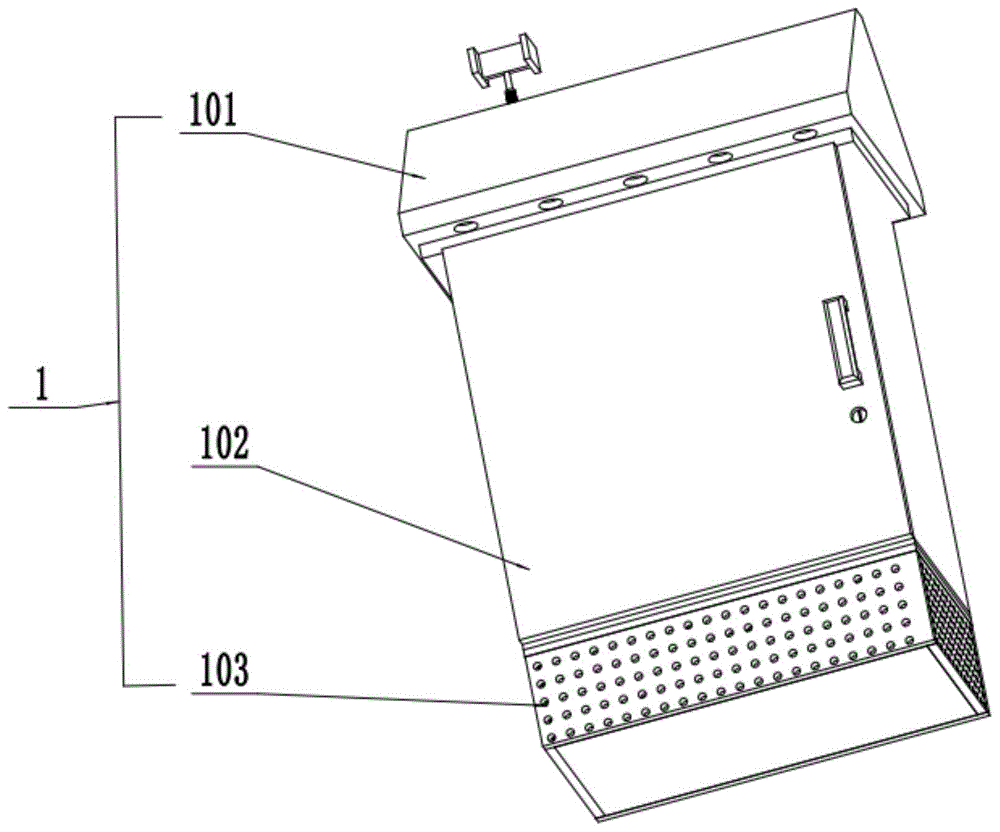
Figure 202011316015

A high-efficiency heat dissipation power distribution cabinet, comprising a casing, a water-cooling part, a fan part, and a motor switching part, characterized in that: the casing comprises: a top casing, a box body casing, a bottom casing, and the top casing is fixedly installed on the top of the box body casing , the top shell is provided with ten exhaust holes; the box shell is installed above the bottom shell; the bottom shell is an insect-proof and dust-proof iron mesh; the motor switching part is installed inside the top shell to detect the wind power Control the motor to work; the semi-circle below the semi-circular rod does not contact the conductive sheet, so the motor is in a stopped working state, and the wind passes through the bottom shell and then changes the direction of the wind through the inclined air inlet, so that the large electric fan generates power to drive the rod A. The rotation follows the rotation of the bevel gear A, the bevel gear B meshing with the bevel gear A rotates, and the circular rod B rotates to drive the electric fan in the water storage tank to rotate to complete the water cooling cycle.

Figure 202011316015

Description

High-efficient heat-dissipation power distribution cabinet
Technical Field
The invention relates to the technical field of power distribution cabinets, in particular to a high-efficiency heat-dissipation power distribution cabinet.
Background
Along with the development of society, the continuous progress of social science and technology, domestic power consumption is also gradually promoted, and people also gradually strengthen the safety consciousness to electrical apparatus, especially 20 years, various novel electrical apparatus have continuously developed, and the problem that comes with it is that people also more and more high to the requirement of power consumption safety, wherein people pay more attention to the degree of safety and the quality of block terminal.
For the current distribution box, the contradiction between the safety degree and the quality of the distribution box is increasingly outstanding, for the current distribution box, only a few simple through holes are arranged in the box body for ventilation, heat dissipation and observation, the wiring of various switches in the box body is scattered and not fixed, the temperature is too high in summer, the heat is passively dissipated only through a few heat dissipation holes, the phenomenon that internal electrical components work abnormally due to the fact that the temperature is too high often occurs, and the problem is to be solved.
Disclosure of Invention
Aiming at the problems, the invention provides a high-efficiency heat-dissipation power distribution cabinet, and the technical scheme adopted by the invention is as follows: a high-efficiency heat-dissipation power distribution cabinet comprises a shell, a water cooling part, a fan part and a motor switching part, and is characterized in that the shell comprises a top shell, a box body shell and a bottom shell, wherein the top shell is fixedly arranged at the top of the box body shell, and ten exhaust holes are formed in the top shell; the box body shell is arranged above the bottom shell; the bottom shell is an insect-proof and dust-proof iron net; the motor switching part is arranged in the top shell and used for detecting the wind power to control the motor to work; the water cooling part is arranged in the box body shell and used for cooling the interior of an electrical element; the fan part is arranged in the box body shell, and natural wind blows from the bottom shell and provides power for the large electric fan through the inclined plane air inlet.
Preferably, the water cooling part comprises a large electric fan, a belt A, a round rod A, a bevel gear B, a round rod B, a water storage tank, a water pipe and an inclined plane air inlet; the large electric fan is rotatably arranged on a shaft in the middle of the inclined plane air inlet; one end of the belt A is fixedly connected with a shaft of the large electric fan, and the other end of the belt A is fixedly connected with the bottom end of the round rod A; the bevel gear A is fixedly arranged on the top end of the round rod A; the bevel gear B is meshed with the bevel gear A; an electric fan is arranged in the water storage tank; the round bar B is fixedly installed by penetrating through the electric fan and the bevel gear B in the water storage tank; when the bevel gear B rotates, the electric fan in the water storage tank is driven to circulate water cooling; the water pipe penetrates through each electric appliance element needing cooling in the power distribution cabinet and is installed on the water storage tank; the inclined plane air inlet is fixedly arranged in the bottom shell.
Preferably, the fan part comprises a gear A, a belt B, a circular shaft with a circular ring, a small cylinder, an iron plate with a groove, a gear B, a long strip with a circular shaft, a sliding rail, a rack with a groove, an L-shaped iron plate, a spring, a long sliding rail and a ventilating pipe; the gear A is fixedly arranged on the round rod B; one end of the belt B is fixedly arranged on the round rod B, and the other end of the belt B is arranged on the round shaft with the circular ring; the upper half part of the small cylinder is rotatably arranged in a round hole of a round shaft with a ring, and the lower half part of the small cylinder is slidably arranged in a groove of an iron plate with a groove; the iron plate with the groove is slidably arranged in the groove of the slide rail; the gear B is rotatably arranged on a shaft at one side of the iron plate with the groove; one end of a strip with a round shaft is rotatably arranged on a shaft of the gear B, the other end of the strip with the round shaft is slidably arranged in a groove of a rack with a groove, and a square on the strip with the round shaft is slidably arranged in a groove of a long slide rail; the sliding rail is fixedly arranged in the box body shell; the rack with the groove is slidably arranged in the L-shaped iron plate, and three springs are arranged above the rack with the groove; the L-shaped iron plate is fixedly arranged in the box body shell; the long slide rail is fixedly arranged in the box body shell; an electric fan is arranged on the shaft in the ventilation pipe, and the shaft of the ventilation pipe is fixedly connected with the shaft on the gear B.
Preferably, the motor switching part comprises a motor, an insulating cylinder, a conducting strip, a disc bracket, an inclined disc, a round rod with a semicircle, a telescopic sleeve, an I-shaped plate and a gear C; the motor is fixedly arranged inside the top shell; the insulating cylinder is fixedly arranged on the upper end surface of the motor; a conducting strip is arranged in the middle of the insulating cylinder; the disc support is fixedly arranged on the upper end face of the insulating cylinder, an inclined disc is arranged in the disc support, and the inclined disc can incline in a direction of three hundred and sixty degrees in the disc support; the round rod with the semicircle is fixedly arranged in the middle of the inclined disc, and the motor can start to work only when the semicircle part of the round rod with the semicircle is contacted with the motor; the round rod with the semicircle is provided with a telescopic sleeve for preventing water from entering and can swing along with the round rod with the semicircle; the I-shaped plate is fixedly arranged on the upper end surface of the round rod with the semicircle; the gear C is fixedly arranged on a motor shaft of the motor; gear C meshes with gear a.
The invention has the beneficial effects that:
1. the electric fan of the ventilation pipe is arranged on the shaft of the gear B, and the electric fan rotates to generate wind power to achieve the refrigeration effect and moves up and down to enable the refrigeration effect to be better and effective
2. The rectangular of taking the circle axle upwards removes along one of them recess on the rack of taking the recess when the iron plate of taking the recess upwards removes, and the rack of taking the recess moves to the pulling force direction under the pulling force of spring when removing the terminal point, and another recess on the rectangular rack that enters into the area recess of taking the circle axle makes the rack of taking the recess and the rectangular of taking the circle axle can not mesh, realizes that gear B rotates towards a direction all the time, reaches the bigger effect of wind-force.
3. When wind power is small or no, the I-shaped plate cannot be blown by the wind power to swing greatly, the semi-circular ball on the circular rod with the semi-circle is contacted with the conducting strip, the motor starts to work, and the energy-saving effect that the motor is not used in the wind is achieved.
Drawings
Fig. 1, 2 and 3 are schematic overall structural diagrams of the present invention.
Fig. 4 is a schematic structural diagram of the water cooling part of the present invention.
Fig. 5, 6 and 7 are schematic structural views of a fan portion according to the present invention.
Fig. 8 and 9 are schematic views of the switching structure of the motor of the present invention.
Fig. 10 is an enlarged structural view of a1 shown in fig. 7 according to the present invention.
Reference numerals: 1-a housing; 2-a water cooling section; 3-a fan section; 4-a motor switching part; 101-a top housing; 102-a case housing; 103-a bottom housing; 201-big electric fan; 202-Belt A; 203-round bar a; 204-bevel gear a; 205-bevel gear B; 206-round bar B; 207-a water storage tank; 208-a water pipe; 209-inclined plane air inlet; 301-gear a; 302-belt B; 303-circular shaft with circular ring; 304-small cylinder; 305-iron plate with groove; 306-gear B; 307-a long strip with a round axis; 308-a slide rail; 309-grooved rack; 310-L-shaped iron plate; 311-a spring; 312-long slide rail; 313-vent tube; 401-an electric machine; 402-an insulating cylinder; 403-a conductive sheet; 404-a disc holder; 405-a bevel disk; 406-round bar with semi-circle; 407-a telescopic sleeve; 408-I type board; 409-gear C.
DETAILED DESCRIPTION OF EMBODIMENT (S) OF INVENTION
The technical scheme of the invention is further specifically described by the following embodiments and the accompanying drawings. In the following description, numerous specific details are set forth in order to provide a thorough understanding of the present invention, but the present invention may be practiced in many ways other than those described herein, and it will be apparent to those skilled in the art that similar modifications can be made without departing from the spirit of the invention, and therefore the invention is not limited to the specific embodiments disclosed below.
In the description of the present invention, it should be noted that the terms "upper", "lower", "front", "back", "left", "right", and the like indicate orientations or positional relationships based on orientations or positional relationships shown in the drawings or orientations or positional relationships that the products of the present invention are conventionally placed in use, and are only used for convenience in describing the present invention and simplifying the description, but do not indicate or imply that the devices or elements referred to must have a specific orientation, be constructed in a specific orientation, and be operated, and thus, should not be construed as limiting the present invention.
Referring to fig. 1, 2, 3, 4, 5, 6, 7, 8, 9 and 10, the efficient heat dissipation power distribution cabinet is shown, which comprises a casing 1, a water cooling part 2, a fan part 3 and a motor switching part 4, and is characterized in that the casing 1 comprises a top casing 101, a box casing 102 and a bottom casing 103, the top casing 101 is fixedly arranged on the top of the box casing 102, and ten exhaust holes are arranged on the top casing 101; the box body shell 102 is arranged above the bottom shell 103; the bottom shell 103 is an insect-proof and dust-proof iron net; the motor switching part 4 is arranged in the top shell 101 and used for detecting the wind power and controlling the motor 401 to work; the water cooling part 2 is arranged inside the box body shell 102 and used for cooling the inside of an electrical element; the fan section 3 is mounted within the housing shell 102 and natural wind is blown from the bottom shell 103 through the angled intake 209 to power the large fan 201.
In an alternative implementation manner of the embodiment of the invention, except for the same parts as the previous embodiment, the water cooling part 2 comprises a large electric fan 201, a belt A202, a round rod A203, a bevel gear A204, a bevel gear B205, a round rod B206, a water storage tank 207, a water pipe 208 and an inclined plane air inlet 209; the large electric fan 201 is rotatably arranged on a shaft in the middle of the inclined plane air inlet 209; one end of the belt A202 is fixedly connected with the shaft of the large electric fan 201, and the other end of the belt A202 is fixedly connected with the bottom end of the round rod A203; the bevel gear A204 is fixedly arranged on the top end of the round rod A203; bevel gear B205 meshes with bevel gear A204; an electric fan is arranged in the water storage tank 207; the round bar B206 is fixedly installed by penetrating through the electric fan in the water storage tank 207 and the bevel gear B205; when the bevel gear B205 rotates, an electric fan in the water storage tank 207 is driven to circulate water cooling; the water pipe 208 penetrates through each electric element needing cooling in the power distribution cabinet and is installed on the water storage tank 207; the angled air inlet 209 is fixedly mounted within the bottom housing 103.
In an alternative implementation manner of the embodiment of the present invention, except for the same components as those in the previous embodiment, the fan part 3 includes a gear a301, a belt B302, a circular shaft 303 with a circular ring, a small cylinder 304, a grooved iron plate 305, a gear B306, a long strip 307 with a circular shaft, a slide rail 308, a grooved rack 309, an L-shaped iron plate 310, a spring 311, a long slide rail 312, and a ventilation pipe 313; the gear A301 is fixedly arranged on the round rod B206; one end of the belt B302 is fixedly arranged on the round rod B206, and the other end of the belt B302 is arranged on the round shaft 303 with a round ring; the upper half part of the small cylinder 304 is rotatably arranged in a round hole of the round shaft 303 with a round ring, and the lower half part of the small cylinder 304 is slidably arranged in a groove of the iron plate 305 with a groove; the iron plate 305 with the groove is slidably arranged in the groove of the sliding rail 308; gear B306 is rotatably mounted on a shaft at one side of the grooved iron plate 305; one end of the strip 307 with the round shaft is rotatably arranged on the shaft of the gear B306, the other end of the strip 307 with the round shaft is slidably arranged in the groove of the rack 309 with the groove, and the square on the strip 307 with the round shaft is slidably arranged in the groove of the long slide rail 312; the slide rail 308 is fixedly arranged inside the box body shell 102; the rack 309 with the groove is slidably arranged inside the L-shaped iron plate 310, and three springs 311 are arranged above the rack 309 with the groove; the L-shaped iron plate 310 is fixedly arranged inside the box body shell 102; the long slide rail 312 is fixedly installed inside the box body shell 102; an electric fan is arranged on a shaft in the ventilation pipe 313, and the shaft of the ventilation pipe 313 is fixedly connected with a shaft on the gear B306.
In an alternative embodiment of this embodiment of the invention, in addition to the same components as in the previous embodiment,
the motor switching part 4 comprises a motor 401, an insulating cylinder 402, a conducting strip 403, a disc bracket 404, an inclined disc 405, a semicircular round rod 406, a telescopic sleeve 407, an I-shaped plate 408 and a gear C409; the motor 401 is fixedly mounted inside the top housing 101; the insulating cylinder 402 is fixedly arranged on the upper end surface of the motor 401; a conducting strip 403 is arranged in the middle of the insulating cylinder 402; the disc support 404 is fixedly arranged on the upper end face of the insulating cylinder 402, an inclined disc 405 is arranged in the disc support 404, and the inclined disc 405 can incline in a direction of three hundred and sixty degrees in the disc support 404; the round bar with semicircle 406 is fixedly arranged in the middle of the bevel disc 405, and the work can be started when the semicircle part of the round bar with semicircle 406 and the round bar with semicircle 406 contact the motor 401; the round rod 406 with the semicircle is provided with a telescopic sleeve 407 which is used for preventing water from entering and can swing along with the round rod 406 with the semicircle; the I-shaped plate 408 is fixedly arranged on the upper end surface of the round rod 406 with the semicircle; the gear C409 is fixedly arranged on a motor 401 shaft of the motor 401; gear C409 meshes with gear a 301.
The working principle is as follows: when wind power can enable the large electric fan to rotate, the I-shaped plate is blown to be inclined by the wind power, because of the structural arrangement of the inclined disc, the inclined disc can be inclined along with the inclined disc, when the inclined disc is inclined, the round rod with the semicircle inclines, the semicircle below the round rod with the semicircle is not contacted with the conducting strip, so that the motor is in a stop working state, the wind power penetrates through the bottom shell, then the direction of the wind is changed by the inclined air inlet, the large electric fan generates power to drive the round rod A to rotate along with the bevel gear A, the bevel gear B meshed with the bevel gear A rotates, the round rod B rotates to drive the electric fan in the water storage tank to rotate, water cooling circulation is completed, the round rod B rotates to drive the belt B to rotate along with the round shaft with the ring, when the round shaft with the ring rotates, the small column moves along the groove of the iron plate with the groove in the groove, because of the design of the groove track, the iron, the electric fan is arranged on the shaft of the gear B, wind power is generated by the rotation of the electric fan, the refrigeration effect is achieved, the refrigeration effect is better and effective due to the fact that the electric fan is installed on the shaft of the gear B, when the iron plate with the groove moves upwards, the strip with the circular shaft moves upwards along one groove on the rack with the groove, when the iron plate with the groove moves to the end point, the rack with the groove moves towards the direction of the pulling force under the pulling force of the spring, the strip with the circular shaft enters the other groove on the rack with the groove, the rack with the groove and the strip with the circular shaft cannot be meshed, the gear B rotates towards one direction all the time, and the effect that the wind power is larger is achieved.
When wind power is low or no wind power exists, the wind power cannot blow the I-shaped plate to shake greatly, the semi-circular ball on the circular rod with the semi-circle is contacted with the conducting strip, the motor starts to work to drive the motor shaft to rotate, the gear C on the motor shaft rotates along with the motor shaft and rotates along with the gear A meshed with the gear C, the circular rod B rotates along with the gear C, and then the water cooling part and the fan part are driven to work.

Claims (4)

1. A high-efficiency heat-dissipation power distribution cabinet comprises a shell (1), a water cooling part (2), a fan part (3) and a motor switching part (4), and is characterized in that the shell (1) comprises a top shell (101), a box body shell (102) and a bottom shell (103), wherein the top shell (101) is fixedly arranged at the top of the box body shell (102), and ten exhaust holes are formed in the top shell (101); the box body shell (102) is arranged above the bottom shell (103); the bottom shell (103) is an insect-proof and dust-proof iron net; the motor switching part (4) is arranged in the top shell (101) and used for detecting the wind power and controlling the motor (401) to work; the water cooling part (2) is arranged inside the box body shell (102) and is used for cooling the inside of an electrical element; the fan part (3) is arranged in the box body shell (102), and natural wind blows from the bottom shell (103) and provides power for the large electric fan (201) through the inclined plane wind inlet (209).
2. The high-efficiency heat-dissipation power distribution cabinet according to claim 1, wherein the water-cooling part (2) comprises a large electric fan (201), a belt A (202), a round rod A (203), a bevel gear A (204), a bevel gear B (205), a round rod B (206), a water storage tank (207), a water pipe (208) and a bevel air inlet (209); the large electric fan (201) is rotatably arranged on a shaft in the middle of the inclined plane air inlet (209); one end of the belt A (202) is fixedly connected with a shaft of the large electric fan (201), and the other end of the belt A (202) is fixedly connected with the bottom end of the round rod A (203); the bevel gear A (204) is fixedly arranged on the top end of the round rod A (203); bevel gear B (205) and bevel gear A (204) are meshed; an electric fan is arranged in the water storage tank (207); the round bar B (206) is fixedly installed by passing through the electric fan and the bevel gear B (205) in the water storage tank (207); when the bevel gear B (205) rotates, an electric fan in the water storage tank (207) is driven to circulate water cooling; the water pipe (208) penetrates through each electric appliance element needing cooling in the power distribution cabinet and is installed on the water storage tank (207); the inclined plane air inlet (209) is fixedly arranged in the bottom shell (103).
3. The efficient heat-dissipation power distribution cabinet according to claim 1, wherein the fan part (3) comprises a gear A (301), a belt B (302), a circular shaft (303) with a circular ring, a small cylinder (304), a grooved iron plate (305), a gear B (306), a long strip (307) with a circular shaft, a sliding rail (308), a grooved rack (309), an L-shaped iron plate (310), a spring (311), a long sliding rail (312) and a ventilation pipe (313); the gear A (301) is fixedly arranged on the round rod B (206); one end of a belt B (302) is fixedly arranged on the round rod B (206), and the other end of the belt BB (302) is arranged on a round shaft (303) with a circular ring; the upper half part of the small cylinder (304) is rotatably arranged in a round hole of the round shaft (303) with a circular ring, and the lower half part of the small cylinder (304) is slidably arranged in a groove of the iron plate (305) with a groove; the iron plate (305) with the groove is slidably arranged in the groove of the sliding rail (308); a gear B (306) is rotatably arranged on a shaft at one side of the iron plate (305) with the groove; one end of a long strip (307) with a round shaft is rotatably arranged on the shaft of the gear B (306), the other end of the long strip (307) with the round shaft is slidably arranged in a groove of a rack (309) with a groove, and a square on the long strip (307) with the round shaft is slidably arranged in a groove of a long slide rail (312); the sliding rail (308) is fixedly arranged in the box body shell (102); the rack (309) with the groove is slidably arranged in the L-shaped iron plate (310), and three springs (311) are arranged above the rack (309) with the groove; the L-shaped iron plate (310) is fixedly arranged in the box body shell (102); the long slide rail (312) is fixedly arranged in the box body shell (102); an electric fan is arranged on a shaft in the ventilation pipe (313), and the shaft of the ventilation pipe (313) is fixedly connected with a shaft on the gear B (306).
4. The efficient heat-dissipation power distribution cabinet according to claim 1, wherein the motor switching part (4) comprises a motor (401), an insulating cylinder (402), a conducting plate (403), a disc support (404), a bevel disc (405), a semicircular round rod (406), a telescopic sleeve (407), an I-shaped plate (408) and a gear C (409); the motor (401) is fixedly arranged inside the top shell (101); the insulating cylinder (402) is fixedly arranged on the upper end surface of the motor (401); a conducting strip (403) is arranged in the middle of the insulating cylinder (402); the disc support (404) is fixedly arranged on the upper end face of the insulating cylinder (402), an inclined disc (405) is arranged in the disc support (404), and the inclined disc (405) can incline in a direction of three hundred and sixty degrees in the disc support (404); the round rod (406) with the semicircle is fixedly arranged in the middle of the bevel disk (405), and the motor (401) can start to work when the semicircle part of the round rod (406) with the semicircle is contacted with the round rod (406) with the semicircle; the round rod (406) with the semicircle is provided with a telescopic sleeve (407) which is used for preventing water from entering and can swing along with the round rod (406) with the semicircle; the I-shaped plate (408) is fixedly arranged on the upper end surface of the round rod (406) with the semicircle; the gear C (409) is fixedly arranged on a motor (401) shaft of the motor (401); the gear C (409) meshes with the gear a (301).
CN202011316015.0A 2020-11-22 2020-11-22 High-efficient heat-dissipation power distribution cabinet Active CN112490874B (en)

Priority Applications (1)

Application Number Priority Date Filing Date Title
CN202011316015.0A CN112490874B (en) 2020-11-22 2020-11-22 High-efficient heat-dissipation power distribution cabinet

Applications Claiming Priority (1)

Application Number Priority Date Filing Date Title
CN202011316015.0A CN112490874B (en) 2020-11-22 2020-11-22 High-efficient heat-dissipation power distribution cabinet

Publications (2)

Publication Number Publication Date
CN112490874A true CN112490874A (en) 2021-03-12
CN112490874B CN112490874B (en) 2022-10-25

Family

ID=74933267

Family Applications (1)

Application Number Title Priority Date Filing Date
CN202011316015.0A Active CN112490874B (en) 2020-11-22 2020-11-22 High-efficient heat-dissipation power distribution cabinet

Country Status (1)

Country Link
CN (1) CN112490874B (en)

Cited By (2)

* Cited by examiner, † Cited by third party
Publication number Priority date Publication date Assignee Title
CN113097905A (en) * 2021-04-30 2021-07-09 吴清玉 Dampproofing protection against insects switch board convenient to heat dissipation
CN115133420A (en) * 2022-07-19 2022-09-30 山东鲁控电力设备有限公司 Low-voltage active dehumidification and heat dissipation type JP cabinet

Citations (8)

* Cited by examiner, † Cited by third party
Publication number Priority date Publication date Assignee Title
CN205985884U (en) * 2016-09-13 2017-02-22 湛江嘉诚科技服务有限公司 Switch board that radiating effect is good
CN106786062A (en) * 2017-01-16 2017-05-31 马鞍山佳夫尼电气科技有限公司 A kind of heat radiating type switch cubicle
CN207164694U (en) * 2017-10-09 2018-03-30 江苏财会职业学院 A kind of computer efficient radiating apparatus
CN207503752U (en) * 2017-09-08 2018-06-15 广东明煌电力工程有限公司 A kind of energy-efficient high efficiency and heat radiation transformer
CN108891267A (en) * 2018-05-02 2018-11-27 杨秀波 A kind of automobile charging pile convenient for heat dissipation
CN209571751U (en) * 2019-05-08 2019-11-01 江苏通强电气设备有限公司 A kind of high voltage power distributing cabinet of perfect heat-dissipating
CN210641250U (en) * 2019-11-06 2020-05-29 胡斌 Low-temperature-keeping electric box
CN210723882U (en) * 2019-11-05 2020-06-09 扬州安普利电力设备有限公司 A dust-proof heat dissipation power distribution box

Patent Citations (8)

* Cited by examiner, † Cited by third party
Publication number Priority date Publication date Assignee Title
CN205985884U (en) * 2016-09-13 2017-02-22 湛江嘉诚科技服务有限公司 Switch board that radiating effect is good
CN106786062A (en) * 2017-01-16 2017-05-31 马鞍山佳夫尼电气科技有限公司 A kind of heat radiating type switch cubicle
CN207503752U (en) * 2017-09-08 2018-06-15 广东明煌电力工程有限公司 A kind of energy-efficient high efficiency and heat radiation transformer
CN207164694U (en) * 2017-10-09 2018-03-30 江苏财会职业学院 A kind of computer efficient radiating apparatus
CN108891267A (en) * 2018-05-02 2018-11-27 杨秀波 A kind of automobile charging pile convenient for heat dissipation
CN209571751U (en) * 2019-05-08 2019-11-01 江苏通强电气设备有限公司 A kind of high voltage power distributing cabinet of perfect heat-dissipating
CN210723882U (en) * 2019-11-05 2020-06-09 扬州安普利电力设备有限公司 A dust-proof heat dissipation power distribution box
CN210641250U (en) * 2019-11-06 2020-05-29 胡斌 Low-temperature-keeping electric box

Cited By (3)

* Cited by examiner, † Cited by third party
Publication number Priority date Publication date Assignee Title
CN113097905A (en) * 2021-04-30 2021-07-09 吴清玉 Dampproofing protection against insects switch board convenient to heat dissipation
CN115133420A (en) * 2022-07-19 2022-09-30 山东鲁控电力设备有限公司 Low-voltage active dehumidification and heat dissipation type JP cabinet
CN115133420B (en) * 2022-07-19 2024-05-17 山东鲁控电力设备有限公司 Low-voltage active dehumidifying and heat-dissipating JP cabinet

Also Published As

Publication number Publication date
CN112490874B (en) 2022-10-25

Similar Documents

Publication Publication Date Title
CN112181095A (en) Computer mainframe who possesses heat dissipation function
CN205827329U (en) A kind of computer multifunctional heat dissipation device
CN208029288U (en) A kind of network server cabinet
CN116505714A (en) One motor with two cooling methods
CN103363758B (en) A kind of refrigerator bottom condenser heat abstractor
CN112490874B (en) High-efficient heat-dissipation power distribution cabinet
CN210723750U (en) A power cabinet with heat dissipation function
CN209546207U (en) A cooling electrical cabinet
CN211607149U (en) Integrated into one piece equipment controlgear of high performance cabinet body
CN205424763U (en) Intelligent stage laser lamp
CN207638502U (en) Cooling device for switched reluctance motor of electric vehicle
CN207340427U (en) A cooling device for an electric cabinet
CN207834528U (en) Electric vehicle battery radiator
CN207647611U (en) A kind of novel diesel generating set
CN105517421A (en) Ionization dust collection device for electronic equipment
CN213522866U (en) A power equipment control cabinet
CN211506368U (en) A server cooling and dust removal device
CN207753626U (en) A kind of radiator of inverter
CN112384036B (en) An electrical automation liquid-cooled high-efficiency heat dissipation device
CN212136162U (en) Outdoor electronic transformer with good heat dissipation effect
CN211182844U (en) A safe and efficient outdoor power equipment cabinet
CN110099545B (en) A terminal device with good cooling effect for 5G communication network
CN201673450U (en) Computer power supply
CN108697032A (en) Electric power electric mounting device with radiator structure
CN207133739U (en) A kind of water-cooled computer cabinet

Legal Events

Date Code Title Description
PB01 Publication
PB01 Publication
SE01 Entry into force of request for substantive examination
TA01 Transfer of patent application right

Effective date of registration: 20221010

Address after: 241000 Guting Road, Nanling Economic Development Zone, Wuhu City, Anhui Province

Applicant after: WUHU JINNIU ELECTRIC Co.,Ltd.

Address before: 066000 No. 550, west section of Hebei Street, Haigang District, Qinhuangdao City, Hebei Province

Applicant before: Sun Xiaoyu

GR01 Patent grant
GR01 Patent grant
TR01 Transfer of patent right

Effective date of registration: 20250822

Address after: 418000, Intersection of Huaibei Road and Yingfeng West Road, Chengbei Street, Hecheng District, Huaihua City, Hunan Province (Huaihua International Trade City) 14-05

Patentee after: Hunan Zhou Ba Intellectual Property Co.,Ltd.

Country or region after: China

Address before: 241000 Guting Road, Nanling Economic Development Zone, Wuhu City, Anhui Province

Patentee before: WUHU JINNIU ELECTRIC Co.,Ltd.

Country or region before: China

TR01 Transfer of patent right

Effective date of registration: 20251210

Address after: 610000 Sichuan Province, Chengdu City, Jinpu High-tech Industrial Park, No. 233 Jinke South Road, 1st Floor, Room 1

Patentee after: Sichuan Daming Tian'an Electric Power Group Co.,Ltd.

Country or region after: China

Address before: 418000, Intersection of Huaibei Road and Yingfeng West Road, Chengbei Street, Hecheng District, Huaihua City, Hunan Province (Huaihua International Trade City) 14-05

Patentee before: Hunan Zhou Ba Intellectual Property Co.,Ltd.

Country or region before: China