CN112484520A - Critical air treatment device for preparing corrosive liquid of electronic product - Google Patents
Critical air treatment device for preparing corrosive liquid of electronic product Download PDFInfo
- Publication number
- CN112484520A CN112484520A CN202011615165.1A CN202011615165A CN112484520A CN 112484520 A CN112484520 A CN 112484520A CN 202011615165 A CN202011615165 A CN 202011615165A CN 112484520 A CN112484520 A CN 112484520A
- Authority
- CN
- China
- Prior art keywords
- air
- water
- air cooler
- main
- outlet
- Prior art date
- Legal status (The legal status is an assumption and is not a legal conclusion. Google has not performed a legal analysis and makes no representation as to the accuracy of the status listed.)
- Pending
Links
Images





Classifications
-
- F—MECHANICAL ENGINEERING; LIGHTING; HEATING; WEAPONS; BLASTING
- F28—HEAT EXCHANGE IN GENERAL
- F28B—STEAM OR VAPOUR CONDENSERS
- F28B7/00—Combinations of two or more condensers, e.g. provision of reserve condenser
-
- F—MECHANICAL ENGINEERING; LIGHTING; HEATING; WEAPONS; BLASTING
- F24—HEATING; RANGES; VENTILATING
- F24H—FLUID HEATERS, e.g. WATER OR AIR HEATERS, HAVING HEAT-GENERATING MEANS, e.g. HEAT PUMPS, IN GENERAL
- F24H3/00—Air heaters
- F24H3/02—Air heaters with forced circulation
-
- F—MECHANICAL ENGINEERING; LIGHTING; HEATING; WEAPONS; BLASTING
- F28—HEAT EXCHANGE IN GENERAL
- F28B—STEAM OR VAPOUR CONDENSERS
- F28B1/00—Condensers in which the steam or vapour is separate from the cooling medium by walls, e.g. surface condenser
- F28B1/02—Condensers in which the steam or vapour is separate from the cooling medium by walls, e.g. surface condenser using water or other liquid as the cooling medium
Landscapes
- Engineering & Computer Science (AREA)
- Mechanical Engineering (AREA)
- General Engineering & Computer Science (AREA)
- Physics & Mathematics (AREA)
- Thermal Sciences (AREA)
- Chemical & Material Sciences (AREA)
- Combustion & Propulsion (AREA)
Abstract
The invention provides a critical air treatment device for preparing an electronic product corrosive liquid, which can generate dry, normal-temperature and clean high-pressure air, thereby being used for producing the electronic product corrosive liquid. It includes high pressure positive blower, high pressure positive blower's air intake connection has primary filter, high pressure positive blower's air outlet has connected gradually one-level air cooler, water knockout drum one, second grade air cooler, water knockout drum two, air heater and high efficiency filter, be equipped with circulating water import and circulating water export on the one-level air cooler, be equipped with refrigerated water import and refrigerated water export on the second grade air cooler, the refrigerated water import with the refrigerated water export respectively with the export and the access connection of cooling water set, the last steam inlet that is equipped with of air heater.
Description
Technical Field
The invention relates to the technical field of air treatment, in particular to a critical air treatment device for preparing an electronic product corrosive liquid.
Background
When the electronic product corrosive liquid is produced, dry and normal-temperature high-pressure air needs to be continuously introduced, but the temperature of the air is often increased to about 65 ℃ after passing through a high-pressure fan, and meanwhile, the humidity is increased, so that the electronic product corrosive liquid cannot be directly used for processing.
Disclosure of Invention
The invention provides a critical air treatment device for preparing an electronic product corrosive liquid, which can generate dry, normal-temperature and clean high-pressure air and can be used for producing the electronic product corrosive liquid, aiming at the problem that the air cannot be used for producing the electronic product corrosive liquid due to the rise of temperature and humidity after passing through a high-pressure fan.
The technical scheme is as follows: a critical formula air treatment device for preparation of electronic product corrosive liquid, it includes high pressure positive blower, its characterized in that: high pressure positive blower's air intake connection has the primary filter, high pressure positive blower's air outlet has connected gradually one-level air cooler, water knockout drum one, second grade air cooler, water knockout drum two, air heater and high efficiency filter, the bottom and the top of one-level air cooler are equipped with circulating water import and circulating water export respectively, bottom and top on the second grade air cooler are equipped with refrigerated water import and refrigerated water export respectively, the refrigerated water import with the refrigerated water export respectively with the export and the access connection of cooling water set, air heater's top and bottom are equipped with steam inlet and outlet respectively, the circulating water import the refrigerated water import with steam inlet is used for letting in heat transfer medium respectively, the circulating water export the refrigerated water export with the outlet is used for discharging heat transfer medium respectively.
It is further characterized in that:
the primary air cooler and the secondary air cooler respectively comprise air cooler shells, air inlets and air outlets which are arranged at the front ends and the rear ends of the air cooler shells, and heat exchange tube boxes which are arranged in the middles of the air cooler shells, wherein the lower ends of the heat exchange tube boxes are provided with the circulating water inlets or the chilled water inlets, and the upper ends of the heat exchange tube boxes are provided with the circulating water outlets or the chilled water outlets;
the inlet and outlet positions of the primary air cooler are respectively provided with a temperature measuring port, and the outlet position of the secondary air cooler is provided with a temperature measuring port;
the heat exchange tube box comprises a main water outlet pipe positioned at the upper part, a main water inlet pipe positioned at the lower part and a fin heat exchange tube positioned between the main water inlet pipe and the main water outlet pipe, the main water inlet pipe is connected with the circulating water inlet or the chilled water inlet, and the main water outlet pipe is connected with the circulating water outlet or the chilled water outlet;
the air heater comprises a heater shell, an air inlet and an air outlet which are arranged at the front end and the rear end of the heater shell, and a heating pipe box arranged in the middle of the heater shell, wherein the upper end of the heating pipe box is provided with the steam inlet, and the lower end of the heating pipe box is provided with the water outlet;
the rear part of the heater shell is also provided with a temperature measuring port;
the heating pipe box comprises a main air inlet pipe positioned at the upper part, a main water drainage pipe positioned at the lower part and a fin heating pipe positioned between the main air inlet pipe and the main water drainage pipe, the main air inlet pipe is connected with the steam inlet, and the main water drainage pipe is connected with the water drainage port;
the first water separator and the second water separator are collecting water separators;
the temperature of the chilled water introduced from the chilled water inlet is 0 ℃; and the temperature of the air discharged by the secondary air cooler is more than 3 ℃.
The invention has the beneficial effects that: the air inhales through high pressure positive blower, carries out the prefilter dust removal through the primary filter simultaneously, then through the dewatering of water knockout drum one simultaneously of one-level air cooler cooling, the rethread second grade air cooler cools down once more and through the dewatering of water knockout drum two, heats up through air heater, lets in high efficiency filter at last and carries out final filtration dust removal, finally can discharge dry, normal atmospheric temperature, clean highly-compressed air, can satisfy the needs of electronic product corrosive liquid preparation.
Drawings
FIG. 1 is a flow chart of the present invention;
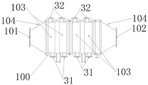
FIG. 2 is a schematic view of a primary air cooler;
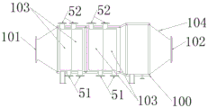
FIG. 3 is a schematic diagram of a two-stage air cooler;
FIG. 4 is a schematic view of a heat exchange tube box;
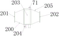
FIG. 5 is a schematic view of an air heater configuration;
FIG. 6 is a schematic view of a heating tube box;
FIG. 7 is a schematic view of the internal structure of the collecting water separator;
FIG. 8 is a schematic view of the connection of the flap to the gusset.
Detailed Description
Fig. 1 shows a critical air treatment device for preparing an etching solution for an electronic product, which includes a high pressure fan 1, an air inlet of the high pressure fan 1 is connected with a primary filter 2, an air outlet of the high pressure fan 1 is sequentially connected with a primary air cooler 3, a first water separator 4, a secondary air cooler 5, a second water separator 6, an air heater 7 and a high efficiency filter 8 through pipelines, as shown in fig. 2 and 3, the primary air cooler 3 is provided with a circulating water inlet 31 and a circulating water outlet 32, the secondary air cooler 5 is provided with a chilled water inlet 51 and a chilled water outlet 52, the chilled water inlet 51 and the chilled water outlet 52 are respectively connected with an outlet and an inlet of a water chilling unit 9 for recycling, and the air heater 7 is provided with a steam inlet 71.
Specifically, the above-mentioned devices may respectively adopt the devices existing in the market, preferably, the primary air cooler 3 and the secondary air cooler 5 respectively include an air cooler casing 100, an air inlet 101 and an air outlet 102 provided at the front and rear ends of the air cooler casing 100, and four heat exchange tube boxes 103 provided in the middle of the air cooler casing 100, the four heat exchange tube boxes 103 are sequentially arranged in front and rear of a shell pass and may be welded and fixed in the casing, the lower end of the heat exchange tube box 103 is provided with a circulating water inlet 31 or a chilled water inlet 51, and the upper end of the heat exchange tube box 103 is provided with a circulating water outlet 32 or a chilled water. The primary air cooler 3 and the secondary air cooler 5 respectively adopt four heat exchange tube boxes 103 for heat exchange cooling, the heat exchange efficiency is high, the heat exchange medium of the primary air cooler 3 adopts circulating water at 32 ℃ close to normal temperature, the heat exchange medium of the secondary air cooler 4 adopts chilled water at 0 ℃ close to normal temperature, heat exchange cooling is carried out in a grading manner, and meanwhile, water distributors are respectively arranged behind the two stages of air coolers for water outlet, so that the water removal effect is ensured; the inlet and outlet positions of the primary air cooler 3 are respectively provided with a temperature measuring port 104, so that the temperature of the entering and discharging air can be measured, the temperature of the circulating water can be adjusted according to the measuring result, and the outlet position of the secondary air cooler 5 is provided with the temperature measuring port 104, so that the temperature of the discharging air can be measured, and the temperature of the chilled water can be adjusted.
Referring to fig. 5, the air heater 7 includes a heater housing 200, an air inlet 201 and an air outlet 202 disposed at the front and rear ends of the heater housing 200, and a heating tube box 203 welded in the middle of the heater housing 200, wherein the upper end of the heating tube box 203 is provided with a steam inlet 71, and the lower end of the heating tube box 203 is provided with a water outlet 204; the rear part of the heater shell 200 is also provided with a temperature measuring port 205 for heating the air after the temperature reduction and the water removal are completed, the heat exchange medium adopts steam, and the temperature of the heat exchange medium can be adjusted as required by measuring the temperature of the discharged air through the temperature measuring port 205.
More specifically, referring to fig. 4, the heat exchange tube box 103 includes a main water outlet tube 1031 located at an upper portion, a main water inlet tube 1032 located at a lower portion, and a finned heat exchange tube 1033 located between the main water inlet tube 1032 and the main water outlet tube 1031, the main water inlet tube 1032 is connected to the circulating water inlet 31 or the chilled water inlet 51, and the main water outlet tube 1031 is connected to the circulating water outlet 32 or the chilled water outlet 52. The liquid heat exchange medium is introduced from the bottom, gradually rises, finally enters the main water outlet pipe 1031 and is discharged, and the heat exchange effect is better compared with the effect of entering from the upper part.
Referring to fig. 6, the heating tube box 203 includes a main intake duct 2031 at an upper portion, a main exhaust duct 2032 at a lower portion, and a fin heating tube 1033 between the main intake duct 2031 and the main exhaust duct 2032, the main intake duct 2031 being connected to the steam inlet 71, and the main exhaust duct 2032 being connected to the exhaust port 204, similarly to the structure of the heat exchange tube box 103; the hot gas heat exchange medium is introduced from the top, gradually descends and finally enters the main water discharge pipe 2032 to be discharged, and the heat exchange effect is better compared with the heat exchange effect of entering from the lower part.
In addition, referring to fig. 7 and 8, the first water separator 4 and the second water separator 6 are collecting water separators. The collecting water separator comprises folded plates 300 which are arranged in parallel up and down, the folded plates 300 are fixed through connecting ribs 301, and the width direction of the folded plates 300 is parallel to the air inlet direction; every department of bending and the end of giving vent to anger at folded plate 300 are provided with right angle board 302 respectively, right angle board 302 sets up along the length direction of folded plate 300, one of them board and folded plate 300 fixed connection of right angle board 302, another board is on a parallel with the direction of admitting air, enclose between right angle board 302 and the folded plate 300 and close and form collecting vat 303, the notch of collecting vat 303 is towards the direction of admitting air, every inclined plane and the acute angle between the direction of admitting air of folded plate 300 equal and be 30, air gets into and removes along folded plate 300 behind the water knockout drum, water droplet in the air receives stopping of collecting vat 303 and falls and discharge through the outlet, thereby realize dividing water.
When the scheme is used for preparing the air for the corrosive liquid of the electronic product, the high-pressure fan 1 sucks the air passing through the primary filter 2 and discharges the air, and the flow rate of the air is 14000Nm3h, the temperature is 65 ℃, the primary filter 2 can adopt a common air primary filter on the market, then the air is cooled by a primary air cooler 3 and is dewatered by a first water separator 4 to discharge air at 45 ℃, the water inlet temperature of the primary air cooler 3 is 32 ℃, the water outlet temperature is 36 ℃, then the air is cooled again by a secondary air cooler 5 and is dewatered by a second water separator 6 to discharge air at 3-4 ℃, the water inlet of the secondary air cooler 5 is chilled water with the temperature of 0 ℃ provided by a water chilling unit 9, the water outlet is 35 ℃, the water outlet enters a water chilling unit 9 (such as a lithium bromide refrigeration unit), the air outlet enters an air heater 7 to be heated, steam with the temperature of more than 20 ℃ is introduced into the air heater 7, the final air temperature is 28 ℃, the relative RH is less than or equal to 21%, and finally the air outlet enters a high-efficiency filter 8 (which can adopt a common high-efficiency air filter on the market) to further remove dust and.
It is also worth mentioning that the first condition for air dehumidification is to cool the air to a temperature below the "supersaturated" dew point temperature by using chilled water to separate the condensed water from the air. The prior air dehumidification generally adopts the following two types of chilled water to cool air, namely: cooling air to 12-13 ℃ by using chilled water at about 7 ℃ (so as to achieve supersaturation); and secondly, cooling the air to 2-3 ℃ by using chilled water at the temperature of-5 ℃ or so (to reach supersaturation). Two types of refrigeration water cooling have disadvantages, namely: the air cooling temperature is relatively high compared with the second type, so the dehumidification (water outlet) effect is relatively poor; and the second method comprises the following steps: the air cooling temperature is low, and the dehumidification (water outlet) effect is relatively good. However, when the working time is long, the heat exchange tubes for cooling the air "frost or ice", the cooling effect drops sharply and the machine cannot be stopped for "defrosting", but the production line is generally not allowed to be stopped at will, and therefore has the same disadvantages. Therefore, the scheme is changed to use 0 ℃ chilled water to cool air (so called critical type), so that the temperature of the air after cooling is always more than 3 ℃, and the phenomenon of frosting or icing on the surface of the heat exchange tube is ensured not to occur.
The process has the following maximum benefits: 1. compared with the first cooling water (7 ℃), the dehumidification effect is greatly improved; and (3) calculating: and (2) according to (compared) calculation of cooling at 8 ℃, the absolute water content in the air can be reduced by more than 38%, and the quality of the air after dehumidification is greatly improved. It is ensured that the finished product does not "cake". 2. Compared with the second cooling water (5 ℃ below zero), the rear troubles of frosting or icing of the heat exchange tube can be eliminated, and the energy consumption can be reduced (compared with the chilled water at 5 ℃ below zero, the refrigerating capacity can be reduced by more than 12%).
The energy-saving economic benefit is estimated by:
(1) after a medium-sized and large-sized fermentation enterprise (for producing threonine or lysine) adopts a 'critical method' dehumidification process, the final quality of a finished product can be greatly improved and ensured. Estimated according to annual yield 5 ten thousand tons/Y: the production time of one year is 300 days; on northern natural air RH superscript (humid) days, 100 days (most conservative) were counted, with evening 1/2 removed and 50 days being the same, resulting in a yield improvement of > 16.67. The occurrence of unqualified products of about 8333 tons (finished product price: the price changes too much due to market fluctuation, and is about 15000 yuan/t at least) can be reduced. The loss is reduced and the loss is calculated at least according to 3%, the economic benefit can be increased to about 375 ten thousand yuan, and at present, more than 30 enterprises for producing large amount of fermentation products in China exist. The economic benefit is huge.
(2) Because the cooled air is not heated by steam, the steam consumption can be saved, according to the calculation of the yield of the finished product in the step (1), one medium-sized and large-sized fermentation enterprise can reduce the steam consumption by about 0.1 t/finished product multiplied by 50000t/Y =5000t, and the steam cost is calculated according to 100 yuan/t, and can reduce the cost by about 50 ten thousand yuan (the whole industry is not estimated).
(3) The two items are summed up as follows: the economic benefit of an enterprise can be increased to 425 million yuan | the estimation of the whole industry is calculated according to that the total yield of 'large amount of amino acid' in 2015 is at least 150 million tons/Y, and the economic benefit of the whole industry can be increased to be more than 1.27 million yuan. And can reduce the carbon emission amount by 7.4 ten thousand tons/Y.
The above description is only for the preferred embodiment of the present invention, but the scope of the present invention is not limited thereto, and any changes or substitutions that can be easily conceived by those skilled in the art within the technical scope of the present invention are included in the scope of the present invention. Therefore, the protection scope of the present invention shall be subject to the protection scope of the claims.
Claims (9)
1. A critical formula air treatment device for preparation of electronic product corrosive liquid, it includes high pressure positive blower, its characterized in that: high pressure positive blower's air intake connection has the primary filter, high pressure positive blower's air outlet has connected gradually one-level air cooler, water knockout drum one, second grade air cooler, water knockout drum two, air heater and high efficiency filter, the bottom and the top of one-level air cooler are equipped with circulating water import and circulating water export respectively, bottom and top on the second grade air cooler are equipped with refrigerated water import and refrigerated water export respectively, the refrigerated water import with the refrigerated water export respectively with the export and the access connection of cooling water set, air heater's top and bottom are equipped with steam inlet and outlet respectively, the circulating water import the refrigerated water import with steam inlet is used for letting in heat transfer medium respectively, the circulating water export the refrigerated water export with the outlet is used for discharging heat transfer medium respectively.
2. The critical air treatment device for preparing the corrosive liquid of the electronic products as claimed in claim 1, wherein: the one-level air cooler with the second grade air cooler includes the air cooler casing respectively, locates air intake and the air outlet of air cooler casing front and back end, locate heat exchange tube case in the middle of the air cooler casing, heat exchange tube case lower extreme is equipped with the circulating water import perhaps the refrigerated water import, heat exchange tube case upper end is equipped with the circulating water export perhaps the refrigerated water export.
3. The critical air treatment device for preparing the corrosive liquid of the electronic products as claimed in claim 2, wherein: the inlet and outlet positions of the first-stage air cooler are respectively provided with a temperature measuring port, and the outlet position of the second-stage air cooler is provided with a temperature measuring port.
4. The critical air treatment device for preparing the corrosive liquid of the electronic products as claimed in claim 2 or 3, wherein: the heat exchange tube case is including being located the main outlet pipe on upper portion, being located the main inlet tube of lower part and being located main inlet tube with fin heat exchange tube between the main outlet pipe, main inlet tube with the circulating water import perhaps chilled water access connection, main outlet pipe with the circulating water export perhaps chilled water exit linkage.
5. The critical air treatment device for preparing the corrosive liquid of the electronic products as claimed in claim 1, wherein: the air heater comprises a heater shell, an air inlet and an air outlet which are arranged at the front end and the rear end of the heater shell, and a heating pipe box arranged in the middle of the heater shell, wherein the upper end of the heating pipe box is provided with the steam inlet, and the lower end of the heating pipe box is provided with the water outlet.
6. The critical air treatment device for preparing the corrosive liquid of the electronic products as claimed in claim 5, wherein: the rear part of the heater shell is also provided with a temperature measuring port.
7. The critical air treatment device for preparing the corrosive liquid of the electronic products as claimed in claim 5 or 6, wherein: the heating tube box comprises a main air inlet pipe positioned at the upper part, a main water drainage pipe positioned at the lower part and a fin heating pipe positioned between the main air inlet pipe and the main water drainage pipe, wherein the main air inlet pipe is connected with the steam inlet, and the main water drainage pipe is connected with the water drainage port.
8. The critical air treatment device for preparing the corrosive liquid of the electronic products as claimed in claim 1, wherein: the first water separator and the second water separator are collecting water separators.
9. A critical air treatment device according to claim 1, wherein: the temperature of the chilled water introduced from the chilled water inlet is 0 ℃; and the temperature of the air discharged by the secondary air cooler is more than 3 ℃.
Priority Applications (1)
| Application Number | Priority Date | Filing Date | Title |
|---|---|---|---|
| CN202011615165.1A CN112484520A (en) | 2020-12-31 | 2020-12-31 | Critical air treatment device for preparing corrosive liquid of electronic product |
Applications Claiming Priority (1)
| Application Number | Priority Date | Filing Date | Title |
|---|---|---|---|
| CN202011615165.1A CN112484520A (en) | 2020-12-31 | 2020-12-31 | Critical air treatment device for preparing corrosive liquid of electronic product |
Publications (1)
| Publication Number | Publication Date |
|---|---|
| CN112484520A true CN112484520A (en) | 2021-03-12 |
Family
ID=74916008
Family Applications (1)
| Application Number | Title | Priority Date | Filing Date |
|---|---|---|---|
| CN202011615165.1A Pending CN112484520A (en) | 2020-12-31 | 2020-12-31 | Critical air treatment device for preparing corrosive liquid of electronic product |
Country Status (1)
| Country | Link |
|---|---|
| CN (1) | CN112484520A (en) |
Citations (6)
| Publication number | Priority date | Publication date | Assignee | Title |
|---|---|---|---|---|
| CN101693868A (en) * | 2009-10-19 | 2010-04-14 | 刘振海 | Energy-saving air preprocessing method and device thereof |
| CN103574805A (en) * | 2013-10-12 | 2014-02-12 | 西安工程大学 | Air-steam condensation system integrating evaporation cooling water chilling unit and evaporation-type condenser |
| CN209612580U (en) * | 2018-12-28 | 2019-11-12 | 无锡海悦生化装备有限公司 | A kind of air dehumidifier cooling for amino acid finished product |
| CN211044033U (en) * | 2019-12-20 | 2020-07-17 | 德清县中能热电有限公司 | Automatic temperature control device of generator air cooler |
| CN111912249A (en) * | 2020-07-29 | 2020-11-10 | 泸州悟净机械科技有限公司 | Energy-saving combined type steam condensing system |
| CN214620711U (en) * | 2020-12-31 | 2021-11-05 | 无锡海悦生化装备有限公司 | Critical air treatment device for preparing corrosive liquid of electronic product |
-
2020
- 2020-12-31 CN CN202011615165.1A patent/CN112484520A/en active Pending
Patent Citations (6)
| Publication number | Priority date | Publication date | Assignee | Title |
|---|---|---|---|---|
| CN101693868A (en) * | 2009-10-19 | 2010-04-14 | 刘振海 | Energy-saving air preprocessing method and device thereof |
| CN103574805A (en) * | 2013-10-12 | 2014-02-12 | 西安工程大学 | Air-steam condensation system integrating evaporation cooling water chilling unit and evaporation-type condenser |
| CN209612580U (en) * | 2018-12-28 | 2019-11-12 | 无锡海悦生化装备有限公司 | A kind of air dehumidifier cooling for amino acid finished product |
| CN211044033U (en) * | 2019-12-20 | 2020-07-17 | 德清县中能热电有限公司 | Automatic temperature control device of generator air cooler |
| CN111912249A (en) * | 2020-07-29 | 2020-11-10 | 泸州悟净机械科技有限公司 | Energy-saving combined type steam condensing system |
| CN214620711U (en) * | 2020-12-31 | 2021-11-05 | 无锡海悦生化装备有限公司 | Critical air treatment device for preparing corrosive liquid of electronic product |
Similar Documents
| Publication | Publication Date | Title |
|---|---|---|
| CN214620710U (en) | Critical air treatment device | |
| CN103225855A (en) | Solution desiccant air handling device circularly driven by multiple stages of heat pumps | |
| CN212778327U (en) | Heat pump type grain drying device | |
| CN214620711U (en) | Critical air treatment device for preparing corrosive liquid of electronic product | |
| CN107014141A (en) | A kind of freezing and refrigeration cabinet performance testing device air treatment system | |
| CN107490110A (en) | Multistage standpipe dew point evaporation cooling handpiece Water Chilling Units | |
| CN113916025A (en) | Dehumidification cooling chamber capable of reducing nylon nitrogen drying energy consumption, system and process method thereof | |
| CN101693868B (en) | Energy-saving air preprocessing method and device thereof | |
| CN201776069U (en) | Freeze drying device | |
| CN112484519A (en) | Critical air treatment device | |
| CN201371022Y (en) | High-efficiency compact energy-saving refrigerated type dryer | |
| CN209612580U (en) | A kind of air dehumidifier cooling for amino acid finished product | |
| CN204107292U (en) | Three-in-one plate changes formula cooling driers | |
| CN208153407U (en) | Intermediate pressure turbine air compressor air intake device | |
| CN202803080U (en) | Modular cold dryer | |
| CN112050326B (en) | Air conditioning unit based on heat pipe-dew point two-stage precooling to prepare cold air and cold water | |
| CN2611840Y (en) | Cool storage compressed air freezing dryer | |
| CN214389537U (en) | Stainless steel plate type cold drying machine | |
| CN108488062A (en) | A kind of low-carbon air compression all-in-one machine | |
| CN216644890U (en) | Hasp area rubberizing drying device convenient to waste heat recovery dehumidifies | |
| CN210801958U (en) | Integral drying device | |
| CN204255046U (en) | Outlet freeze-day with constant temperature machine | |
| CN210845825U (en) | Intelligent air compression drying system for improving safety coefficient of air storage tank | |
| CN201534837U (en) | Energy-saving type air pre-processing device | |
| CN208920621U (en) | Water-cooled freezing machine |
Legal Events
| Date | Code | Title | Description |
|---|---|---|---|
| PB01 | Publication | ||
| PB01 | Publication | ||
| SE01 | Entry into force of request for substantive examination | ||
| SE01 | Entry into force of request for substantive examination | ||
| RJ01 | Rejection of invention patent application after publication | ||
| RJ01 | Rejection of invention patent application after publication |
Application publication date: 20210312 |