CN112453528A - Long-life forming superhard cutter - Google Patents
Long-life forming superhard cutter Download PDFInfo
- Publication number
- CN112453528A CN112453528A CN202011372442.0A CN202011372442A CN112453528A CN 112453528 A CN112453528 A CN 112453528A CN 202011372442 A CN202011372442 A CN 202011372442A CN 112453528 A CN112453528 A CN 112453528A
- Authority
- CN
- China
- Prior art keywords
- cutter
- boss
- milling
- cutting edge
- center
- Prior art date
- Legal status (The legal status is an assumption and is not a legal conclusion. Google has not performed a legal analysis and makes no representation as to the accuracy of the status listed.)
- Granted
Links
- 238000005520 cutting process Methods 0.000 claims abstract description 60
- 238000003801 milling Methods 0.000 claims abstract description 48
- 238000003466 welding Methods 0.000 claims description 3
- 238000007493 shaping process Methods 0.000 claims description 2
- 229910000831 Steel Inorganic materials 0.000 abstract description 6
- 239000010959 steel Substances 0.000 abstract description 6
- WFKWXMTUELFFGS-UHFFFAOYSA-N tungsten Chemical compound [W] WFKWXMTUELFFGS-UHFFFAOYSA-N 0.000 abstract description 6
- 229910052721 tungsten Inorganic materials 0.000 abstract description 6
- 239000010937 tungsten Substances 0.000 abstract description 6
- 229910000838 Al alloy Inorganic materials 0.000 abstract description 5
- 238000003754 machining Methods 0.000 abstract description 4
- 230000000694 effects Effects 0.000 abstract description 3
- 238000005299 abrasion Methods 0.000 description 3
- 238000004519 manufacturing process Methods 0.000 description 3
- 238000012423 maintenance Methods 0.000 description 2
- 238000005498 polishing Methods 0.000 description 2
- 230000009286 beneficial effect Effects 0.000 description 1
- 230000007547 defect Effects 0.000 description 1
- 238000002347 injection Methods 0.000 description 1
- 239000007924 injection Substances 0.000 description 1
- 238000000034 method Methods 0.000 description 1
- 238000012986 modification Methods 0.000 description 1
- 230000004048 modification Effects 0.000 description 1
- 230000002035 prolonged effect Effects 0.000 description 1
Images


Classifications
-
- B—PERFORMING OPERATIONS; TRANSPORTING
- B23—MACHINE TOOLS; METAL-WORKING NOT OTHERWISE PROVIDED FOR
- B23C—MILLING
- B23C5/00—Milling-cutters
- B23C5/02—Milling-cutters characterised by the shape of the cutter
Landscapes
- Engineering & Computer Science (AREA)
- Mechanical Engineering (AREA)
- Milling Processes (AREA)
Abstract
The invention discloses a long-life forming superhard cutter, which solves the problems that when an aluminum alloy shell of a notebook is machined by milling, the service life of a conventional tungsten steel welded ball cutter is short, the machining surface effect is poor and the wire mark is easy to occur, and adopts the technical scheme that a cutter head comprises a central boss, a cutter platform and a milling cutter, the cutter rod is fixedly connected with the center of the central boss, the cutter platform is connected with the central boss into a whole, the cutter platform comprises a first boss, a second boss and a third boss, the central shaft of the cutter rod is taken as the central shaft of the central boss, the cutter platform is arranged in a staggered way by taking the central shaft of the central boss at the side periphery of the central boss, a cutting groove is formed between every two cutter platforms, the milling cutter comprises a first cutting edge, a second cutting edge and a third cutting edge, the milling cutter is fixedly connected with the cutter platform, one side connected with the cutter platform is a back side, the other side is a front side, the front side of the first cutting, one end of the milling cutter, which is far away from the cutter bar, protrudes out of the cutter table.
Description
Technical Field
The invention relates to the technical field of cutters, in particular to a long-life forming superhard cutter.
Background
The tool is a tool used for cutting in machine manufacturing, also called as a cutting tool, when an aluminum alloy shell of a notebook computer is milled, because the machined blank surface is large, most of the existing tools are tungsten steel welded ball cutter tools with the edge diameter of 40mm, the tool made of tungsten steel has large abrasion degree, short service life of machining, poor quality of machined surface effect and easy line marks.
At present, the chinese utility model patent of publication number CN207288993U discloses a novel high rigidity ball sword, including cutter arbor, processing portion and main cutting edge, the one end of cutter arbor is equipped with processing portion, and processing portion's head is equipped with the circular arc cutting edge, and processing portion's afterbody is equipped with chamfer processing sword, the last fixed main cutting edge that is equipped with of circular arc cutting edge.
Although the device has the advantages of simple structure, low manufacturing cost and strong practicability, when the aluminum alloy shell of the notebook computer is milled, the ball knife made of tungsten steel has large abrasion degree, is easy to generate line marks on the surface of a blank, and is not beneficial to the whole process of a finished product.
Disclosure of Invention
Aiming at the defects in the prior art, the invention aims to provide a long-service-life forming superhard cutter which can change the height of an injection mold during maintenance in time according to the maintenance requirement.
In order to achieve the purpose, the invention provides the following technical scheme that the long-life forming superhard cutter comprises a cutter head and a cylindrical cutter bar, wherein the cutter head comprises a central boss, a cutter table and a milling cutter, the cutter bar is fixedly connected with the center of the central boss, the cutter table is connected with the central boss into a whole, the cutter table comprises a first boss, a second boss and a third boss, the central shaft of the cutter bar is used as the central shaft of the central boss, the cutter table is arranged in a staggered mode on the side circumference of the central boss by using the central shaft of the central boss, a first cutting groove is formed between the first boss and the second boss, a second cutting groove is formed between the second boss and the third boss, a third cutting groove is formed between the third boss and the first boss, the milling cutter comprises a first cutting edge, a second cutting edge and a third cutting edge, and the first cutting edge is fixedly connected with one surface of the first cutting groove, which is close to the first boss, the milling cutter is characterized in that one side, close to the second boss, of the second cutting edge is fixedly connected with one side, close to the second boss, of the second cutting groove, one side, close to the third boss, of the third cutting edge is fixedly connected with one side, close to the third boss, of the third cutting groove, one side, connected with the cutter holder, of the milling cutter is the back side, the other side of the milling cutter is the front side, the front side of the first cutting edge, the front side of the second cutting edge and the front side of the third cutting edge are arranged in a crossed mode.
Further setting the following steps: and one end of the cutter table, which is far away from the central shaft of the cutter table, is a smooth round surface.
Further setting the following steps: one side of the cutter platform is an inclined plane inclined towards the cutter bar, and the other side of the cutter platform is connected with the cutter bar into a whole.
The milling cutter is formed by welding PCD, and the diameter of the cutting edge of the milling cutter is 40 mm.
Further setting the following steps: and the joint of the cutter table and the central boss is subjected to chamfering treatment.
In summary, the invention has the following advantages: the milling cutter mills alternately, so that the service life of the milling cutter is prolonged, the replacement times of the milling cutter are reduced, the surface lines after milling are fine, the problem that line marks are easily caused by a conventional ball cutter milling mode is solved, the polishing amount of subsequent processing is reduced, and the milling efficiency is greatly improved.
Drawings
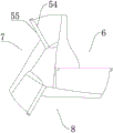
FIG. 1 is an isometric view of example 1;
FIG. 2 is a front view of embodiment 1;
FIG. 3 is a right side view of FIG. 2 of embodiment 1.
In the figure, 1, a tool bit; 2. a cutter bar; 3. a central boss; 4. a tool post; 41. a first boss; 42. a second boss; 43. a third boss; 5. milling cutters; 51. a first blade; 52. a second blade; 53. a third blade; 54. a back side; 55. a front side; 6. a first cut groove; 7. a second cut groove; 8. and a third cutting groove.
Detailed Description
The present invention will be described in further detail with reference to the accompanying drawings.
as shown in fig. 1 and 3, the cutter head 1 includes a central boss 3, a cutter table 4 and a milling cutter 5, the cutter bar 2 is fixedly connected with the center of the central boss 3, the cutter table 4 is connected with the central boss 3 into a whole, the cutter table 4 includes a first boss 41, a second boss 42 and a third boss 43, the central axis of the cutter bar 2 is taken as the central axis of the central boss 3, the cutter table 4 is arranged in a staggered way on the side circumference of the central boss 3 with the central axis of the central boss 3, a first cutting groove 6 is arranged between the first boss 41 and the second boss 42, a second cutting groove 7 is arranged between the second boss 42 and the third boss 43, a third cutting groove 8 is arranged between the third boss 43 and the first boss 41, the milling cutter 5 includes a first cutting edge 51, a second cutting edge 52 and a third cutting edge 53, the first cutting edge 51 is fixedly connected with the surface of the first cutting groove 6 close to the first boss 41, the second cutting edge 52 is fixedly connected with the surface of the second cutting, the third cutting edge 53 is fixedly connected with one surface of the third cutting groove 8 close to the third boss 43, the surface of the milling cutter 5 connected with the cutter table 4 is a back surface 54, the other surface is a front surface 55, the front surface 55 of the first cutting edge 51, the front surface 55 of the second cutting edge 52 and the front surface 55 of the third cutting edge 53 are crosswise arranged by taking the central shaft of the cutter bar 2 as the center for 120 degrees, and one end of the milling cutter 5 far away from the cutter bar 2 protrudes out of the cutter table 4.
As shown in fig. 1, the end of the tool post 4 away from the central axis of the tool post 4 is a smooth circular surface.
As shown in fig. 2, one surface of the tool post 4 is a slope inclined toward the tool holder 2, and the other surface is integrally connected to the tool holder 2.
As shown in fig. 1 and 3, the milling cutter 5 is formed by welding PCD, the diameter of the cutting edge of the milling cutter 5 is 40mm, and the joint of the cutter table 4 and the central boss 3 is chamfered.
When the milling cutter is used specifically by a person in the field, the cutter bar 2 is fixed through a vertical machining numerical control center milling machine, then the milling machine drives the cutter head 1 to rotate at a high speed to start machining a blank, through a mode that the front face 55 of the first cutting edge 51, the front face 55 of the second cutting edge 52 and the front face 55 of the third cutting edge 53 are arranged in a crossed mode by taking the central axis of the cutter bar 2 as the center by 120 degrees, the part, protruding out of the cutter table 4, of the milling cutter 5 can perform alternate milling on the aluminum alloy blank, the milling cutter 5 can be cooled more fully during the alternate milling, the surface abrasion degree of the milling cutter 5 is slowed down, the longer service life of the milling cutter 5 is facilitated, after the cutter head 1 rotates at a high speed, the part, far away from one end of the cutter bar 2, protruding out of the cutter table 4 is in contact with the.
The conventionality is to the aluminum alloy shell of notebook computer during, because the blank face ratio of processing is great, and current cutter is mostly 40 mm's tungsten steel welded ball sword cutter, through the stock inlet wire, the mode that the ball sword milled is processed, and the cutter degree of wear that this kind of tungsten steel made is big, and life is not high, and the surface effect quality of processing is poor, has the line mark easily.
By the mode of milling the three milling cutters 5 staggered by 120 degrees, the service life of the milling cutters 5 is 5 times of that of a ball cutter, the replacement times of the cutter head 1 are reduced, grains on the surface of a blank milled by each milling cutter 5 are thinner, the polishing amount of subsequent processing is reduced, the overall milling efficiency is faster than that of the ball cutter milling mode, and the production efficiency is improved.
The above-mentioned embodiments are merely illustrative and not restrictive, and those skilled in the art can make modifications to the embodiments without inventive contribution as required after reading the present specification, but only protected by the patent laws within the scope of the claims.
Claims (5)
1. The utility model provides a shaping superhard cutter of high life, includes tool bit and cylindric cutter arbor, its characterized in that: the cutter head comprises a center boss, a cutter holder and a milling cutter, the cutter holder is fixedly connected with the center of the center boss, the cutter holder is connected with the center boss into a whole, the cutter holder comprises a first boss, a second boss and a third boss, the center shaft of the cutter holder is used as the center shaft of the center boss, the cutter holder is arranged on the outer circumferential surface of the center boss in a staggered mode by using the center shaft of the center boss, a first cutting groove is formed between the first boss and the second boss, a second cutting groove is formed between the second boss and the third boss, a third cutting groove is formed between the third boss and the first boss, the milling cutter comprises a first cutting edge, a second cutting edge and a third cutting edge, the first cutting edge is fixedly connected with one surface of the first cutting groove close to the first boss, the second cutting edge is fixedly connected with one surface of the second boss close to the second cutting groove, and the third cutting edge is fixedly connected with one surface of the third cutting groove close to the third, the milling cutter is characterized in that one side, connected with the cutter holder, of the milling cutter is the back side, the other side of the milling cutter is the front side, the front side of the first cutter edge, the front side of the second cutter edge and the front side of the third cutter edge are arranged in a 120-degree crossed mode by taking the central axis of the cutter holder as the center, and one end, far away from the cutter holder, of the milling cutter protrudes.
2. A long-life formed superhard cutter as claimed in claim 1, wherein: and one end of the cutter table, which is far away from the central shaft of the cutter table, is a smooth round surface.
3. A long-life formed superhard cutter as claimed in claim 1, wherein: one side of the cutter platform is an inclined plane inclined towards the cutter bar, and the other side of the cutter platform is connected with the cutter bar into a whole.
4. A long-life formed superhard cutter as claimed in claim 1, wherein: the milling cutter is formed by welding PCD, and the diameter of the cutting edge of the milling cutter is 40 mm.
5. A long-life formed superhard cutter as claimed in claim 1, wherein: and the joint of the cutter table and the central boss is subjected to chamfering treatment.
Priority Applications (1)
| Application Number | Priority Date | Filing Date | Title |
|---|---|---|---|
| CN202011372442.0A CN112453528B (en) | 2020-11-30 | 2020-11-30 | Super hard cutter of long life-span shaping |
Applications Claiming Priority (1)
| Application Number | Priority Date | Filing Date | Title |
|---|---|---|---|
| CN202011372442.0A CN112453528B (en) | 2020-11-30 | 2020-11-30 | Super hard cutter of long life-span shaping |
Publications (2)
| Publication Number | Publication Date |
|---|---|
| CN112453528A true CN112453528A (en) | 2021-03-09 |
| CN112453528B CN112453528B (en) | 2024-08-16 |
Family
ID=74805949
Family Applications (1)
| Application Number | Title | Priority Date | Filing Date |
|---|---|---|---|
| CN202011372442.0A Active CN112453528B (en) | 2020-11-30 | 2020-11-30 | Super hard cutter of long life-span shaping |
Country Status (1)
| Country | Link |
|---|---|
| CN (1) | CN112453528B (en) |
Citations (3)
| Publication number | Priority date | Publication date | Assignee | Title |
|---|---|---|---|---|
| US20130078044A1 (en) * | 2011-09-26 | 2013-03-28 | Kennametal Inc. | Milling cutter for cutting a ninety-degree shoulder in a workpiece |
| CN210280799U (en) * | 2019-06-13 | 2020-04-10 | 苏州金巨源五金机电有限公司 | One-step forming cutter for boss holes |
| CN213729577U (en) * | 2020-11-30 | 2021-07-20 | 国宏工具系统(无锡)股份有限公司 | Long-life forming superhard cutter |
-
2020
- 2020-11-30 CN CN202011372442.0A patent/CN112453528B/en active Active
Patent Citations (3)
| Publication number | Priority date | Publication date | Assignee | Title |
|---|---|---|---|---|
| US20130078044A1 (en) * | 2011-09-26 | 2013-03-28 | Kennametal Inc. | Milling cutter for cutting a ninety-degree shoulder in a workpiece |
| CN210280799U (en) * | 2019-06-13 | 2020-04-10 | 苏州金巨源五金机电有限公司 | One-step forming cutter for boss holes |
| CN213729577U (en) * | 2020-11-30 | 2021-07-20 | 国宏工具系统(无锡)股份有限公司 | Long-life forming superhard cutter |
Also Published As
| Publication number | Publication date |
|---|---|
| CN112453528B (en) | 2024-08-16 |
Similar Documents
| Publication | Publication Date | Title |
|---|---|---|
| CN106363374B (en) | A kind of numerical-control processing method in compressor rotor blade type face | |
| CN104084773B (en) | A kind of processing technique of xial flow steam turbine blade | |
| CN102091919A (en) | Machining method of three-dimensional closed impeller | |
| CN213729577U (en) | Long-life forming superhard cutter | |
| CN201239817Y (en) | Novel efficient cyclone milling head | |
| CN101412121A (en) | Method for processing high power medium-speed diesel linkage rod tooth form and special processing knife tool | |
| CN112453528B (en) | Super hard cutter of long life-span shaping | |
| CN219358055U (en) | Grinding-free double-cutter-head machine-clamped blade type slot cutter | |
| CN216990051U (en) | Milling cutter with unequal blade diameters | |
| CN101716688A (en) | Processing method of special electric power fitting taper sleeve taper hole for carbon fibre compound core wires and special device thereof | |
| CN101386081A (en) | Whirlwind milling cutter | |
| CN107745146B (en) | Milling method of cast aluminum thin-wall part | |
| CN112893880B (en) | Method for processing shallow groove on retaining ring | |
| CN110181239A (en) | A kind of PCD dock cutter making technique | |
| CN222856819U (en) | Multi-edge ball end milling cutter | |
| CN113290649A (en) | Combined cutter for woodworking processing counter bore | |
| CN220311881U (en) | Ceramic end mill for cutting high-temperature alloy | |
| CN214920827U (en) | Cutter for processing eccentric nose mold | |
| CN220533060U (en) | Milling ball cutter structure | |
| CN218745099U (en) | Center avoiding type drilling and milling cutter | |
| CN214978021U (en) | Internal spherical surface forming milling cutter | |
| CN219924669U (en) | PCBN milling cutter blade | |
| CN220093157U (en) | Combined cutter integrating plane milling and C-shaped three-dimensional surface milling | |
| CN216176923U (en) | Improved cutter | |
| CN216065721U (en) | A kind of ultra-fine tungsten carbide steel milling cutter |
Legal Events
| Date | Code | Title | Description |
|---|---|---|---|
| PB01 | Publication | ||
| PB01 | Publication | ||
| SE01 | Entry into force of request for substantive examination | ||
| SE01 | Entry into force of request for substantive examination | ||
| GR01 | Patent grant | ||
| GR01 | Patent grant |