Cutting equipment for machining laminate flooring
Technical Field
The invention relates to the technical field of laminate flooring processing, in particular to cutting equipment for laminate flooring processing.
Background
The floor is one of ornamental material, and the floor adds man-hour and need cut the composite sheet after the compression, obtains required shape, generally holds up the composite sheet through the manual work at present, adopts the electric saw to cut, and stability is low, the operation degree of difficulty is big, work efficiency is low, adopts this kind of mode to easily hinder workman's hand, has the potential safety hazard, and simultaneously, the composite sheet is also very easily the off tracking when cutting, leads to producing cutting error.
The cutting equipment on the market is various and can basically meet the use requirements of people, but certain problems still exist, and the specific problems comprise the following points:
1. when the cutting equipment is used, the limiting function is generally difficult to realize, so that the floor deflection phenomenon is easy to occur when the device is used;
2. when the cutting equipment is used, a protection function is rarely arranged, so that the safety of the cutting equipment is reduced;
3. the dust absorption of the cutting equipment is more complicated when in use, thereby reducing the practicability of the device.
Disclosure of Invention
The invention aims to provide cutting equipment for machining a laminate flooring, which aims to solve the problems that in the background art, the limiting function is difficult to realize, the protection function is rarely set, and dust collection is complicated.
In order to achieve the purpose, the invention provides the following technical scheme: including placing platform and fixed plate, the both sides of placing the bench top portion all are fixed with the fixed plate, and the surface of fixed plate both sides all is fixed with the screw, the surface threaded connection of screw one end has an adjusting screw section of thick bamboo, the surface mounting of fixed plate one side has servo motor, and servo motor's output passes through the shaft coupling and installs the lead screw to the surface of lead screw one end is articulated each other with the surface of fixed plate, the surface thread cover of lead screw is equipped with the regulating block, and the one end of regulating block is fixed with the cylinder, the output of cylinder is fixed with fixed frame, the internally mounted of fixed frame has driving motor, and driving motor's output passes through the shaft coupling and installs the pivot, and the one end of pivot is fixed with the cutting knife, the cutting knife both sides of fixed frame bottom all are provided with protection machanism, the surface mounting of placing the platform, The input ends of the servo motor, the driving motor and the induced draft fan are electrically connected.
Preferably, the inside of placing the platform is seted up the dust absorption cavity, and places the platform surface below the dust absorption cavity and seted up the collection cavity to the inside of collecting the cavity has placed the dust storage drawer.
Preferably, the surface of one end of the adjusting screw cylinder is hinged with a limiting plate, and the limiting plate is internally hinged with equally spaced limiting rollers.
Preferably, protection frame, adjusting spring, spout and pin have been set gradually from top to bottom in protection machanism's inside, the cutting knife both sides of fixed frame bottom all are fixed with the protection frame, and the spout has all been seted up to the inside both sides of protection frame.
Preferably, the inside of spout is provided with the pin, and the top of pin installs adjusting spring to the surface of adjusting spring one end and the inner wall fixed connection of protective frame.
Preferably, equidistant gas pocket has all been seted up on the platform surface of placing at dust absorption cavity top, and the dust absorption cavity internally mounted of gas pocket below has the draught fan.
Compared with the prior art, the invention has the beneficial effects that: the cutting equipment for processing the laminate flooring not only avoids the floor deflection phenomenon when the device is used, realizes the protection function of the device, but also improves the practicability of the device;
1. by arranging the limiting rollers, the screws, the adjusting screw cylinders and the limiting plates, when the device is used, the device is firstly placed at a specified position, then a floor to be cut is placed between the limiting rollers on the surface of the placing table, then the adjusting screw cylinders are rotated under the action of the screws to drive the limiting plates to move, the limiting rollers are driven to move under the action of the limiting plates to fixedly clamp the floor, the limiting function of the device is realized, and the phenomenon that the floor deflects when the device is used is avoided;
2. the stop rod moves to one side of the cutting knife in the sliding groove under the action of the adjusting spring through the sliding groove, the stop rod and the protective frame, the cutting knife is protected, and the stop rod moves to the inner part of the protective frame during cutting, so that the protective function of the device is realized, and the safety during use is improved;
3. through being provided with storage dirt drawer, lead screw, gas pocket and draught fan, through operation control button in the cutting process, start the inside draught fan of dust absorption cavity, make the draught fan inhale to collecting the cavity inside with impurity such as dust under the effect of gas pocket to the gathering is in the inside of storing up the dirt drawer, treats to cut the completion back, takes out the storage dirt drawer, handles the inside dust of storage dirt drawer, has realized the dust absorption function of device, thereby has improved the practicality of device.
Drawings
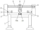
FIG. 1 is a schematic front view of the present invention;
FIG. 2 is a schematic side view of the cross-sectional structure of the present invention;
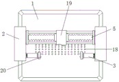
FIG. 3 is a schematic top view of the present invention;
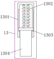
fig. 4 is an enlarged structural schematic diagram of the protection mechanism of the invention.
In the figure: 1. a placing table; 2. a fixing plate; 3. adjusting the screw cylinder; 4. a screw; 5. a screw rod; 6. a cylinder; 7. a cutting knife; 701. a rotating shaft; 8. a servo motor; 9. a limiting plate; 10. a control button; 11. a fixing frame; 12. a drive motor; 13. a protection mechanism; 1301. a protective frame; 1302. adjusting the spring; 1303. a chute; 1304. a stop lever; 14. a dust collection cavity; 15. a collection chamber; 16. a dust storage drawer; 17. an induced draft fan; 18. air holes; 19. an adjusting block; 20. and (5) limiting rollers.
Detailed Description
The technical solutions in the embodiments of the present invention will be clearly and completely described below with reference to the drawings in the embodiments of the present invention, and it is apparent that the described embodiments are only a part of the embodiments of the present invention, and not all embodiments, and furthermore, the terms "first", "second", "third", "upper, lower, left, right", and the like are used for descriptive purposes only and are not to be construed as indicating or implying relative importance. Meanwhile, in the description of the present invention, unless otherwise explicitly specified or limited, the terms "connected" and "connected" should be interpreted broadly, for example, as being fixedly connected, detachably connected, or integrally connected; the connection can be mechanical connection or electrical connection; the embodiments of the present invention can be directly connected or indirectly connected through an intermediary, and all other embodiments obtained by those skilled in the art without any creative efforts belong to the protection scope of the present invention.
The structure of the cutting equipment for machining the laminate flooring is shown in fig. 1 and 2, and comprises a placing table 1 and a fixing plate 2, wherein a dust suction cavity 14 is formed in the placing table 1, a collecting cavity 15 is formed in the surface of the placing table 1 below the dust suction cavity 14, a dust storage drawer 16 is arranged in the collecting cavity 15, air holes 18 with equal intervals are formed in the surface of the placing table 1 at the top of the dust suction cavity 14, and a draught fan 17 is arranged in the dust suction cavity 14 below the air holes 18 and used for dust suction work of the device;
further, as shown in fig. 1, 2 and 3, two sides of the top of the placing table 1 are both fixed with a fixing plate 2, and surfaces of two sides of the fixing plate 2 are both fixed with screws 4, a surface thread of one end of each screw 4 is connected with an adjusting barrel 3, and a surface of one end of each adjusting barrel 3 is hinged with a limit plate 9, and the inside of each limit plate 9 is hinged with a limit roller 20 with equal spacing, a surface of one side of the fixing plate 2 is mounted with a servo motor 8, and an output end of the servo motor 8 is mounted with a lead screw 5 through a coupler, and a surface of one end of the lead screw 5 is hinged with a surface of the fixing plate 2, a surface thread of the lead screw 5 is sleeved with an adjusting block 19, and one end of the adjusting block 19 is fixed with a cylinder 6, an output end of the cylinder fixing frame 6 is fixed with a fixing frame 11, an inside, a cutting knife 7 is fixed at one end of the rotating shaft 701 and used for limiting the device;
further, as shown in fig. 2 and 4, both sides of the cutting knife 7 at the bottom of the fixing frame 11 are provided with the protection mechanisms 13, the protection frame 1301, the adjusting spring 1302, the sliding groove 1303 and the stop lever 1304 are sequentially arranged inside the protection mechanisms 13 from top to bottom, the protection frame 1301 is fixed on both sides of the cutting knife 7 at the bottom of the fixing frame 11, the sliding groove 1303 is arranged on both sides inside the protection frame 1301, the stop lever 1304 is arranged inside the sliding groove 1303, the adjusting spring 1302 is installed at the top of the stop lever 1304, the surface of one end of the adjusting spring 1302 is fixedly connected with the inner wall of the protection frame 1301, the surface of the placing table 1 is fixed with the control button 10, and the output end of the control button 10 is electrically connected with the input ends of the air cylinder 6, the servo motor 8, the driving motor 12 and the induced draft fan 17 respectively.
The working principle is as follows: when the device is used, the device is placed at a specified position, then a floor to be cut is placed between the limiting rollers 20 on the surface of the placing table 1, the adjusting screw cylinder 3 is rotated under the action of the screw 4 to drive the limiting plate 9 to move, the limiting rollers 20 are driven to move under the action of the limiting plate 9, the floor is fixedly clamped, the limiting function of the device is achieved, and the phenomenon that the floor deflects when the device is used is avoided;
at this time, under the action of the adjusting spring 1302, the stop lever 1304 moves to one side of the cutting knife 7 in the chute 1303 to protect the cutting knife 7, and during cutting, the stop lever 1304 moves to the inside of the protective frame 1301 to realize the protective function of the device, so that the safety during use is improved;
by operating the control button 10, the control button 10 controls the air cylinder 6, the servo motor 8 and the driving motor 12 to work, the cutting knife 7 in the fixed frame 11 is pushed to move downwards under the action of the cylinder 6, the cutting knife 7 is driven to rotate under the action of the driving motor 12, the floor is cut, the screw rod 5 is driven to rotate under the action of the servo motor 8, the adjusting block 19 is driven to move, the cutting knife 7 is driven to move, cutting the floor, starting the induced draft fan 17 in the dust absorption cavity 14 by operating the control button 10 in the cutting process, leading the induced draft fan 17 to absorb impurities such as dust and the like into the collection cavity 15 under the action of the air holes 18, and collected in the interior of the dust storage drawer 16, and after the cutting is completed, the dust storage drawer 16 is drawn out, the dust in the dust storage drawer 16 is treated to realize the dust absorption function of the device, so that the practicability of the device is improved; finally, the use work of the cutting equipment is finished.
It will be evident to those skilled in the art that the invention is not limited to the details of the foregoing illustrative embodiments, and that the present invention may be embodied in other specific forms without departing from the spirit or essential attributes thereof. The present embodiments are therefore to be considered in all respects as illustrative and not restrictive, the scope of the invention being indicated by the appended claims rather than by the foregoing description, and all changes which come within the meaning and range of equivalency of the claims are therefore intended to be embraced therein. Any reference sign in a claim should not be construed as limiting the claim concerned.