CN112413370A - Intelligent manufacturing hemispherical camera capable of being installed rapidly - Google Patents
Intelligent manufacturing hemispherical camera capable of being installed rapidly Download PDFInfo
- Publication number
- CN112413370A CN112413370A CN202011239139.3A CN202011239139A CN112413370A CN 112413370 A CN112413370 A CN 112413370A CN 202011239139 A CN202011239139 A CN 202011239139A CN 112413370 A CN112413370 A CN 112413370A
- Authority
- CN
- China
- Prior art keywords
- rod
- camera
- push rod
- support frame
- stop lever
- Prior art date
- Legal status (The legal status is an assumption and is not a legal conclusion. Google has not performed a legal analysis and makes no representation as to the accuracy of the status listed.)
- Withdrawn
Links
- 238000004519 manufacturing process Methods 0.000 title claims abstract description 7
- 238000004140 cleaning Methods 0.000 claims description 16
- 230000005389 magnetism Effects 0.000 claims description 8
- 230000007246 mechanism Effects 0.000 claims description 8
- 230000000087 stabilizing effect Effects 0.000 claims description 7
- 238000009434 installation Methods 0.000 abstract description 14
- 230000000694 effects Effects 0.000 abstract description 9
- 230000009471 action Effects 0.000 abstract description 4
- 239000000428 dust Substances 0.000 description 2
- 230000004075 alteration Effects 0.000 description 1
- 238000005452 bending Methods 0.000 description 1
- 230000009286 beneficial effect Effects 0.000 description 1
- 238000005034 decoration Methods 0.000 description 1
- 230000007547 defect Effects 0.000 description 1
- 238000001125 extrusion Methods 0.000 description 1
- 230000004048 modification Effects 0.000 description 1
- 238000012986 modification Methods 0.000 description 1
- 230000001737 promoting effect Effects 0.000 description 1
- 238000007789 sealing Methods 0.000 description 1
- 238000006467 substitution reaction Methods 0.000 description 1
Images




Classifications
-
- F—MECHANICAL ENGINEERING; LIGHTING; HEATING; WEAPONS; BLASTING
- F16—ENGINEERING ELEMENTS AND UNITS; GENERAL MEASURES FOR PRODUCING AND MAINTAINING EFFECTIVE FUNCTIONING OF MACHINES OR INSTALLATIONS; THERMAL INSULATION IN GENERAL
- F16M—FRAMES, CASINGS OR BEDS OF ENGINES, MACHINES OR APPARATUS, NOT SPECIFIC TO ENGINES, MACHINES OR APPARATUS PROVIDED FOR ELSEWHERE; STANDS; SUPPORTS
- F16M13/00—Other supports for positioning apparatus or articles; Means for steadying hand-held apparatus or articles
- F16M13/02—Other supports for positioning apparatus or articles; Means for steadying hand-held apparatus or articles for supporting on, or attaching to, an object, e.g. tree, gate, window-frame, cycle
-
- B—PERFORMING OPERATIONS; TRANSPORTING
- B08—CLEANING
- B08B—CLEANING IN GENERAL; PREVENTION OF FOULING IN GENERAL
- B08B1/00—Cleaning by methods involving the use of tools
- B08B1/10—Cleaning by methods involving the use of tools characterised by the type of cleaning tool
- B08B1/12—Brushes
-
- B—PERFORMING OPERATIONS; TRANSPORTING
- B08—CLEANING
- B08B—CLEANING IN GENERAL; PREVENTION OF FOULING IN GENERAL
- B08B11/00—Cleaning flexible or delicate articles by methods or apparatus specially adapted thereto
-
- G—PHYSICS
- G03—PHOTOGRAPHY; CINEMATOGRAPHY; ANALOGOUS TECHNIQUES USING WAVES OTHER THAN OPTICAL WAVES; ELECTROGRAPHY; HOLOGRAPHY
- G03B—APPARATUS OR ARRANGEMENTS FOR TAKING PHOTOGRAPHS OR FOR PROJECTING OR VIEWING THEM; APPARATUS OR ARRANGEMENTS EMPLOYING ANALOGOUS TECHNIQUES USING WAVES OTHER THAN OPTICAL WAVES; ACCESSORIES THEREFOR
- G03B17/00—Details of cameras or camera bodies; Accessories therefor
- G03B17/02—Bodies
-
- H—ELECTRICITY
- H04—ELECTRIC COMMUNICATION TECHNIQUE
- H04N—PICTORIAL COMMUNICATION, e.g. TELEVISION
- H04N23/00—Cameras or camera modules comprising electronic image sensors; Control thereof
Landscapes
- Engineering & Computer Science (AREA)
- General Engineering & Computer Science (AREA)
- Multimedia (AREA)
- Signal Processing (AREA)
- Physics & Mathematics (AREA)
- General Physics & Mathematics (AREA)
- Mechanical Engineering (AREA)
- Accessories Of Cameras (AREA)
Abstract
The invention relates to the technical field of video recording equipment, and discloses an intelligently manufactured quickly-installed hemispherical camera which comprises an installation frame, wherein an embedded rod is fixedly installed inside the installation frame, a stop lever is rotatably installed inside the embedded rod, a contact is arranged inside the stop lever, a common magnet is arranged in the middle of the stop lever, an electromagnet is fixedly installed on the inner side of a sliding rail, a limiting rod is movably installed below the stop lever, a sliding rod is movably installed below the limiting rod, and the camera is fixedly connected with a support frame. This hemisphere camera that intelligent manufacturing can swiftly install, when crossing the gag lever post through the top of support frame, the gag lever post resets under spacing spring action and blocks the support frame, and when the camera was dismantled, the top of support frame promoted the pin and rotates for contact on the pin contacts each other, if the camera is inside still at the circular telegram, then the electro-magnet circular telegram hinders the pin and rotates, has realized that the camera installation is firm and has prevented the effect of other people's stealing the camera.
Description
Technical Field
The invention relates to the technical field of shooting and recording equipment, in particular to an intelligently manufactured hemispherical camera capable of being quickly installed.
Background
The hemispherical camera is small in size, attractive in appearance and suitable for office places and places with high decoration grade, and is mainly characterized by being exquisite in design, attractive in appearance and easy to install, wherein the hemispherical camera is formed by a camera, an automatic aperture manual zoom lens, a spherical cover with excellent sealing performance and a precise camera installation support.
The hemisphere camera is in the installation, mainly adopts the screw fixation, there is the screw phenomenon that produces the corruption easily after using for a long time, lead to the installation screw to drop because of the corruption or utilize the screw to steal the camera easily, the camera can gather a lot of dust influences on the mirror surface after using for a long time simultaneously and shoot and record, and the camera is generally installed when eminence clearance relatively troublesome, extravagant manpower very much, then, in view of this, the intelligent hemisphere camera that can swiftly install of making is provided.
Disclosure of the invention technical problem (1)
Aiming at the defects of the prior art, the invention provides the intelligent manufactured quickly-mountable hemispherical camera, which has the advantages of firm installation, difficulty in stealing, automatic mirror cleaning and the like, and solves the problems that a screw is easy to corrode, a mirror is easy to steal, the automatic mirror cleaning cannot be realized and the like after the existing camera is installed.
(II) technical scheme
In order to realize the purposes of firm installation, difficult theft and automatic mirror cleaning, the invention provides the following technical scheme:
an intelligently manufactured quickly-mountable hemispherical camera comprises a mounting frame, wherein a mounting mechanism is fixedly mounted inside the mounting frame, an embedded rod is fixedly mounted inside the mounting mechanism, the embedded rod is fixedly connected with the mounting frame, a stop lever is rotatably mounted inside the embedded rod, a contact is arranged inside the stop lever, a common magnet is arranged in the middle of the stop lever, a slide rail is fixedly mounted on the right side of the common magnet, the slide rail is fixedly connected with the embedded rod, an electromagnet is fixedly mounted on the inner side of the slide rail, a limit lever is movably mounted below the stop lever, a limit spring is fixedly mounted on the outer side of the limit lever, a slide rod is movably mounted below the limit lever, a support spring is fixedly mounted on the outer side of the slide rod, a rotating rod is rotatably mounted below the slide rod, a driving rod is rotatably mounted between the rotating rods, a reset spring is fixedly mounted below the driving rod, and, the below movable mounting of pre-buried pole has the support frame, the top movable mounting of support frame has the loose collar, the below fixed mounting of loose collar has auxiliary spring, the outside of support frame is rotated and is installed the shift ring, the below of shift ring is rotated and is installed first push rod, the below of first push rod is rotated and is connected with the second push rod, the below outside swing joint of second push rod has the stopper, the outer fixed mounting of stopper has extension spring, the lower extreme movable mounting of second push rod has the cleaning brush, the cleaning brush rotate with the second push rod and be connected, the below fixed mounting of cleaning brush has the camera, camera and support frame fixed connection.
Preferably, the electromagnet is electrified to generate the same magnetism as that generated by the common magnet on the opposite surface, and the generated same magnetism can repel the stop lever to prevent the stop lever from rotating.
Preferably, the outside of gag lever post is provided with the dog that corresponds with the slide bar, and the gag lever post promotes the slide bar through the dog and moves to the inboard when removing, can prevent that others from stealing.
Preferably, the inboard of dwang is provided with the hypotenuse the same with the inboard inclination of slide bar, and the hypotenuse that inclination is the same makes things convenient for the slide bar to reset under the supporting spring effect.
Preferably, a driving motor is arranged inside the moving ring, and when the driving motor is started, the moving ring rotates downwards along the supporting frame.
Preferably, a limiting hole is formed in the first push rod, a stabilizing spring is fixedly mounted in the second push rod, a sliding block is movably mounted at the upper end of the stabilizing spring, and the diameter of the sliding block corresponds to that of the limiting hole in the first push rod.
(III) advantageous effects
Compared with the prior art, the invention provides an intelligently manufactured hemispherical camera capable of being quickly installed, which has the following beneficial effects:
1. this intelligent manufacturing can swiftly install hemisphere camera, through upwards promoting the support frame, make the top of support frame promote the gag lever post and move to the outside, when the gag lever post is crossed on the top of support frame, the gag lever post resets under limiting spring action and blocks the support frame inside pre-buried pole, when the camera needs to be dismantled, the top of support frame promotes the pin and rotates, make contact mutual contact on the pin, if the camera is inside still being switched on this moment, then the electro-magnet circular telegram produces the magnetism opposite with ordinary magnet, hinder the pin and rotate, it opens the dwang to need artifical manual rotation actuating lever simultaneously, just can guarantee that the slide bar does not have the interference effect to the gag lever post, realized that the camera installation is firm and prevent the effect of stealing of other people to the camera through intelligent manufacturing.
2. This hemisphere camera that can swiftly install is made to intelligence, when the mirror surface through the camera appears fuzzy, can the inside driving motor of automatically start shift ring, make the shift ring rotate downwards along the support frame, thereby promote first push rod downstream, make the clearance brush of second push rod lower extreme downstream, when junction and camera top contact between first push rod and the second push rod, the second push rod receives the extrusion and rotates, its inside slider and spacing hole contact, make the second push rod keep the bending state, drive the mirror surface bottom of clearance brush to the camera under extension spring's effect and clear up, the effect to the automatic clearance of the mirror surface intelligence of camera has been realized, the cost of labor is reduced.
Drawings
FIG. 1 is a schematic view of the interior of the structure of the present invention;
FIG. 2 is a cross-sectional view of the mounting mechanism of the present invention;
FIG. 3 is an enlarged view of the structure shown in FIG. 2 at A according to the present invention;
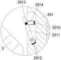
FIG. 4 is an enlarged view of the structure shown at B in FIG. 2 according to the present invention;
FIG. 5 is an enlarged view of the structure of FIG. 4 at C;
FIG. 6 is a schematic view of a partial cross-section of the connection between the support frame and the camera head of the present invention;
FIG. 7 is an enlarged view of the structure of FIG. 6 at D in accordance with the present invention;
FIG. 8 is a schematic top view of the connection of the stand and the camera head of the present invention;
FIG. 9 is a partial cross-sectional view of the connection of the first and second push rods according to the present invention.
In the figure: 1. a mounting frame; 2. an installation mechanism; 201. pre-burying a rod; 2011. a stop lever; 2012. a contact; 2013. a common magnet; 2014. a slide rail; 2015. an electromagnet; 202. a limiting rod; 2021. a slide bar; 2022. a support spring; 2023. rotating the rod; 2024. a drive rod; 2025. a return spring; 203. a limiting spring; 3. a support frame; 301. a movable ring; 302. an auxiliary spring; 4. a moving ring; 5. a first push rod; 501. a limiting hole; 6. a second push rod; 601. a stabilizing spring; 602. a slider; 7. a limiting block; 701. an extension spring; 8. a cleaning brush.
Detailed Description
The technical solutions in the embodiments of the present invention will be clearly and completely described below with reference to the drawings in the embodiments of the present invention, and it is obvious that the described embodiments are only a part of the embodiments of the present invention, and not all of the embodiments. All other embodiments, which can be derived by a person skilled in the art from the embodiments given herein without making any creative effort, shall fall within the protection scope of the present invention.
Referring to fig. 1-9, an intelligently manufactured quickly-mountable hemispherical camera includes a mounting frame 1, a mounting mechanism 2 is fixedly mounted inside the mounting frame 1, an embedded rod 201 is fixedly mounted inside the mounting mechanism 2, the embedded rod 201 is fixedly connected with the mounting frame 1, a stop rod 2011 is rotatably mounted inside the embedded rod 201, a contact 2012 is disposed inside the stop rod 2011, a common magnet 2013 is disposed in the middle of the stop rod 2011, a slide rail 2014 is fixedly mounted on the right side of the common magnet 2013, the slide rail 2014 is fixedly connected with the embedded rod 201, an electromagnet 2015 is fixedly mounted on the inner side of the slide rail 2014, the magnetism generated by electrifying the electromagnet 2015 is the same as the magnetism generated by the common magnet 2013 on the opposite side, the generated magnetism is the same as that can repel the stop rod 2011 to prevent the stop rod 2011 from rotating, a limit rod 202 is movably mounted below the stop rod 2011, a stop block corresponding to the sliding rod 2021 is disposed, when the limiting rod 202 moves, the sliding rod 2021 is pushed by the stop to move inwards to prevent stealing, the limiting spring 203 is fixedly mounted on the outer side of the limiting rod 202, the sliding rod 2021 is movably mounted below the limiting rod 202, the supporting spring 2022 is fixedly mounted on the outer side of the sliding rod 2021, the rotating rod 2023 is rotatably mounted below the sliding rod 2021, the inclined edge which is the same as the inclined angle of the inner side of the sliding rod 2021 is arranged on the inner side of the rotating rod 2023, the inclined edge which is the same as the inclined angle facilitates the sliding rod 2021 to reset under the action of the supporting spring 2022, the driving rod 2024 is rotatably mounted between the rotating rods 2023, the reset spring 2025 is fixedly mounted below the driving rod 2024, two ends of the reset spring 2025 are fixedly connected with the rotating rod 2023, the supporting frame 3 is movably mounted below the embedded rod 201, the movable ring 301 is movably mounted above the supporting frame 3, and the.
A moving ring 4 is rotatably mounted on the outer side of the support frame 3, a driving motor is arranged inside the moving ring 4, when the driving motor is started, the moving ring 4 rotates downwards along the support frame 3, a first push rod 5 is rotatably mounted below the moving ring 4, a second push rod 6 is rotatably connected below the first push rod 5, a limit hole 501 is formed inside the first push rod 5, a stabilizing spring 601 is fixedly mounted inside the second push rod 6, a slide block 602 is movably mounted at the upper end of the stabilizing spring 601, the diameter of the slide block 602 corresponds to that of the limit hole 501 inside the first push rod 5, a limit block 7 is movably connected on the outer side below the second push rod 6, an extension spring 701 is fixedly mounted outside the limit block 7, a cleaning brush 8 is movably mounted at the lower end of the second push rod 6, the cleaning brush 8 is rotatably connected with the second push rod 6, a camera 9 is fixedly mounted below the cleaning brush 8, the camera 9 is fixedly connected with the support frame 3.
The working principle is as follows: during installation, the embedded rod 201 is fixedly installed inside the installation frame 1, then the top end of the support frame 3 provided with the camera 9 is aligned with the installation hole inside the embedded rod 2, the support frame 3 is pushed upwards, meanwhile, the drive rod 2024 is manually rotated to prop open the rotating rod 2023, so that the top end of the support frame 3 pushes the limiting rod 202 to move outwards, when the top end of the support frame 3 crosses the limiting rod 202, the limiting rod 202 is reset under the action of the limiting spring 203 to clamp the support frame 3 inside the embedded rod 201, when the camera 9 needs to be disassembled, the top end of the support frame 3 pushes the stop rod 2011 to rotate, so that the contacts 2012 on the stop rod 2011 are contacted with each other, if the inside of the camera 9 is still electrified, the electromagnet 2015 is electrified to generate magnetism opposite to the common magnet 2013, the stop rod 2011 is prevented from rotating, and meanwhile, the 2023 needs to be manually rotated to open the drive rod 2024, so as, there is not the interference effect to gag lever post 202, has guaranteed that the camera installation is firm, can not cause camera 9 to drop because of the screw corruption to and prevent someone other to the robbing of camera 9 through intelligent manufacturing.
After long-time use, a large amount of dust can be accumulated on the mirror surface of the camera 9, when the mirror surface of the camera 9 is fuzzy, the driving motor inside the moving ring 4 can be intelligently started, so that the moving ring 4 rotates downwards along the supporting frame 3, the first push rod 5 and the second push rod 6 are pushed to move downwards, the cleaning brush 8 at the lower end of the second push rod 6 moves downwards, the second push rod 6 is always pulled by the extension spring 701 through the limiting block 7, the cleaning brush is always attached to the spherical mirror surface of the camera 9, meanwhile, as the moving ring 4 rotates, the cleaning brush 8 rotates to clean the mirror surface of the camera 9, when the joint between the first push rod 5 and the second push rod 6 is in contact with the maximum diameter of the top end of the hemisphere of the camera 9, the joint between the first push rod 5 and the second push rod 6 is extruded, so that the second push rod 6 rotates, the slide block 602 inside the second push rod is in contact with the limiting hole 501, make second push rod 6 keep crooked state, drive clearance brush 8 under extension spring 701's effect and clear up the mirror surface bottom of camera 9 to realized the automatic clearance of mirror surface intelligence to camera 9, reduced the cost of labor.
Although embodiments of the present invention have been shown and described, it will be appreciated by those skilled in the art that changes, modifications, substitutions and alterations can be made in these embodiments without departing from the principles and spirit of the invention, the scope of which is defined in the appended claims and their equivalents.
Claims (6)
1. The utility model provides a hemisphere camera that intelligent manufacturing can swiftly install, includes mounting bracket (1), its characterized in that: the inner fixed mounting of the mounting rack (1) is provided with a mounting mechanism (2), the inner fixed mounting of the mounting mechanism (2) is provided with a pre-buried rod (201), the pre-buried rod (201) is fixedly connected with the mounting rack (1), the inner part of the pre-buried rod (201) is rotatably provided with a stop lever (2011), the inside of the stop lever (2011) is provided with a contact (2012), the middle of the stop lever (2011) is provided with a common magnet (2013), the right side of the common magnet (2013) is fixedly provided with a slide rail (2014), the slide rail (2014) is fixedly connected with the pre-buried rod (201), the inner side of the slide rail (2014) is fixedly provided with an electromagnet (2015), the lower part of the stop lever (2011) is movably provided with a limit rod (202), the outer side of the limit rod (202) is fixedly provided with a limit spring (203), the lower part of the limit rod (202) is movably provided with, a rotating rod (2023) is rotatably installed below the sliding rod (2021), a driving rod (2024) is rotatably installed between the rotating rods (2023), a reset spring (2025) is fixedly installed below the driving rod (2024), two ends of the reset spring (2025) are fixedly connected with the rotating rod (2023), a support frame (3) is movably installed below the embedded rod (201), a movable ring (301) is movably installed above the support frame (3), an auxiliary spring (302) is fixedly installed below the movable ring (301), a movable ring (4) is rotatably installed outside the support frame (3), a first push rod (5) is rotatably installed below the movable ring (4), a second push rod (6) is rotatably connected below the first push rod (5), a limiting block (7) is movably connected outside the second push rod (6), a tension spring (701) is fixedly installed outside the limiting block (7), the lower extreme movable mounting of second push rod (6) has cleaning brush (8), cleaning brush (8) with second push rod (6) rotate be connected, the below fixed mounting of cleaning brush (8) has camera (9), camera (9) and support frame (3) fixed connection.
2. The intelligently manufactured and quickly installable hemispherical camera of claim 1, wherein: the magnetism generated by electrifying the electromagnet (2015) is the same as that generated by the common magnet (2013) on the opposite surface.
3. The intelligently manufactured and quickly installable hemispherical camera of claim 1, wherein: a stop block corresponding to the sliding rod (2021) is arranged on the outer side of the limiting rod (202).
4. The intelligently manufactured and quickly installable hemispherical camera of claim 1, wherein: the inner side of the rotating rod (2023) is provided with a bevel edge with the same inclination angle as the inner side of the sliding rod (2021).
5. The intelligently manufactured and quickly installable hemispherical camera of claim 1, wherein: and a driving motor is arranged in the moving ring (4).
6. The intelligently manufactured and quickly installable hemispherical camera of claim 1, wherein: spacing hole (501) have been seted up to the inside of first push rod (5), and the inside fixed mounting of second push rod (6) has stabilizing spring (601), and the upper end movable mounting of stabilizing spring (601) has slider (602), and the diameter size of slider (602) corresponds with the diameter size of spacing hole (501) inside first push rod (5).
Priority Applications (1)
| Application Number | Priority Date | Filing Date | Title |
|---|---|---|---|
| CN202011239139.3A CN112413370A (en) | 2020-11-09 | 2020-11-09 | Intelligent manufacturing hemispherical camera capable of being installed rapidly |
Applications Claiming Priority (1)
| Application Number | Priority Date | Filing Date | Title |
|---|---|---|---|
| CN202011239139.3A CN112413370A (en) | 2020-11-09 | 2020-11-09 | Intelligent manufacturing hemispherical camera capable of being installed rapidly |
Publications (1)
| Publication Number | Publication Date |
|---|---|
| CN112413370A true CN112413370A (en) | 2021-02-26 |
Family
ID=74782130
Family Applications (1)
| Application Number | Title | Priority Date | Filing Date |
|---|---|---|---|
| CN202011239139.3A Withdrawn CN112413370A (en) | 2020-11-09 | 2020-11-09 | Intelligent manufacturing hemispherical camera capable of being installed rapidly |
Country Status (1)
| Country | Link |
|---|---|
| CN (1) | CN112413370A (en) |
Cited By (2)
| Publication number | Priority date | Publication date | Assignee | Title |
|---|---|---|---|---|
| CN112323998A (en) * | 2020-11-10 | 2021-02-05 | 邓家珍 | Building heat insulation board capable of being quickly positioned and installed |
| CN114593326A (en) * | 2022-03-08 | 2022-06-07 | 广东工贸职业技术学院 | Adjustable AGV dolly is with mechanism of making a video recording |
-
2020
- 2020-11-09 CN CN202011239139.3A patent/CN112413370A/en not_active Withdrawn
Cited By (3)
| Publication number | Priority date | Publication date | Assignee | Title |
|---|---|---|---|---|
| CN112323998A (en) * | 2020-11-10 | 2021-02-05 | 邓家珍 | Building heat insulation board capable of being quickly positioned and installed |
| CN114593326A (en) * | 2022-03-08 | 2022-06-07 | 广东工贸职业技术学院 | Adjustable AGV dolly is with mechanism of making a video recording |
| CN114593326B (en) * | 2022-03-08 | 2023-04-18 | 广东工贸职业技术学院 | Adjustable AGV dolly is with mechanism of making a video recording |
Similar Documents
| Publication | Publication Date | Title |
|---|---|---|
| CN215990971U (en) | Self-cleaning night vision camera | |
| CN210927731U (en) | Intelligent security monitoring device convenient to improve shooting definition | |
| CN112576913B (en) | Security protection monitoring platform for residential property | |
| CN208257924U (en) | A kind of outdoor video head convenient for lens cleaning | |
| CN214976056U (en) | Monitoring device for circuit transmission of power internet of things | |
| CN219875885U (en) | Camera mounting structure | |
| CN112273341A (en) | Mobile phone 5G network remote sharing control real fish fishing robot | |
| CN113418120B (en) | Security protection equipment of intelligence house | |
| CN211146016U (en) | Installation is stabilized and is prevented surveillance camera head of slope | |
| CN209009834U (en) | A kind of electric power cable windings frame for building | |
| CN217857578U (en) | Outdoor surveillance camera machine with structure keeps off rain | |
| CN215569133U (en) | Intelligent home safety early warning camera installation device and protection and fixing mechanism thereof | |
| CN217508894U (en) | Automatic curriculum recording and playing device | |
| CN212987003U (en) | Garden street lamp | |
| CN115451303A (en) | Monitoring system of power supply equipment and anti-interference electric control equipment thereof | |
| CN205142348U (en) | Surveillance camera head that can stably adjust | |
| CN212745883U (en) | Artificial intelligence camera equipment | |
| CN214480834U (en) | Dish market intelligent monitoring is with rotatory camera | |
| CN204244346U (en) | A kind of video camera | |
| CN207702049U (en) | A kind of gardens multi-angle monitoring device | |
| CN215000665U (en) | Artificial intelligence monitoring device easy to assemble | |
| CN113596405A (en) | Campus safety monitoring equipment for video structured platform | |
| CN222441769U (en) | Waterproof fog security protection camera | |
| CN218217515U (en) | High-definition spherical camera | |
| CN221991291U (en) | Indoor surveillance camera machine |
Legal Events
| Date | Code | Title | Description |
|---|---|---|---|
| PB01 | Publication | ||
| PB01 | Publication | ||
| SE01 | Entry into force of request for substantive examination | ||
| SE01 | Entry into force of request for substantive examination | ||
| WW01 | Invention patent application withdrawn after publication |
Application publication date: 20210226 |
|
| WW01 | Invention patent application withdrawn after publication |