CN112405196A - Deburring device for motor housing production - Google Patents
Deburring device for motor housing production Download PDFInfo
- Publication number
- CN112405196A CN112405196A CN202011434408.1A CN202011434408A CN112405196A CN 112405196 A CN112405196 A CN 112405196A CN 202011434408 A CN202011434408 A CN 202011434408A CN 112405196 A CN112405196 A CN 112405196A
- Authority
- CN
- China
- Prior art keywords
- wall
- fixed
- motor housing
- bolts
- rotating
- Prior art date
- Legal status (The legal status is an assumption and is not a legal conclusion. Google has not performed a legal analysis and makes no representation as to the accuracy of the status listed.)
- Withdrawn
Links
- 238000004519 manufacturing process Methods 0.000 title claims abstract description 27
- 230000007246 mechanism Effects 0.000 claims abstract description 11
- 238000003825 pressing Methods 0.000 claims description 16
- 238000004804 winding Methods 0.000 claims description 7
- 239000000853 adhesive Substances 0.000 claims description 5
- 230000001070 adhesive effect Effects 0.000 claims description 4
- 230000008878 coupling Effects 0.000 claims description 2
- 238000010168 coupling process Methods 0.000 claims description 2
- 238000005859 coupling reaction Methods 0.000 claims description 2
- 238000000034 method Methods 0.000 abstract description 10
- 230000008569 process Effects 0.000 abstract description 4
- 238000004140 cleaning Methods 0.000 abstract description 3
- 230000000694 effects Effects 0.000 description 6
- 230000007547 defect Effects 0.000 description 2
- 238000009434 installation Methods 0.000 description 2
- 238000010030 laminating Methods 0.000 description 2
- 238000005096 rolling process Methods 0.000 description 2
- 230000009471 action Effects 0.000 description 1
- 230000009286 beneficial effect Effects 0.000 description 1
- 230000000740 bleeding effect Effects 0.000 description 1
- 238000002788 crimping Methods 0.000 description 1
- 230000005574 cross-species transmission Effects 0.000 description 1
- 238000009826 distribution Methods 0.000 description 1
- 238000004880 explosion Methods 0.000 description 1
- 239000008187 granular material Substances 0.000 description 1
- 230000005012 migration Effects 0.000 description 1
- 238000013508 migration Methods 0.000 description 1
- 239000003973 paint Substances 0.000 description 1
- 239000002245 particle Substances 0.000 description 1
- 230000002093 peripheral effect Effects 0.000 description 1
- 238000005507 spraying Methods 0.000 description 1
- 238000003756 stirring Methods 0.000 description 1
- 230000001360 synchronised effect Effects 0.000 description 1
Images




Classifications
-
- B—PERFORMING OPERATIONS; TRANSPORTING
- B24—GRINDING; POLISHING
- B24B—MACHINES, DEVICES, OR PROCESSES FOR GRINDING OR POLISHING; DRESSING OR CONDITIONING OF ABRADING SURFACES; FEEDING OF GRINDING, POLISHING, OR LAPPING AGENTS
- B24B9/00—Machines or devices designed for grinding edges or bevels on work or for removing burrs; Accessories therefor
- B24B9/02—Machines or devices designed for grinding edges or bevels on work or for removing burrs; Accessories therefor characterised by a special design with respect to properties of materials specific to articles to be ground
- B24B9/04—Machines or devices designed for grinding edges or bevels on work or for removing burrs; Accessories therefor characterised by a special design with respect to properties of materials specific to articles to be ground of metal, e.g. skate blades
-
- B—PERFORMING OPERATIONS; TRANSPORTING
- B24—GRINDING; POLISHING
- B24B—MACHINES, DEVICES, OR PROCESSES FOR GRINDING OR POLISHING; DRESSING OR CONDITIONING OF ABRADING SURFACES; FEEDING OF GRINDING, POLISHING, OR LAPPING AGENTS
- B24B27/00—Other grinding machines or devices
- B24B27/0076—Other grinding machines or devices grinding machines comprising two or more grinding tools
-
- B—PERFORMING OPERATIONS; TRANSPORTING
- B24—GRINDING; POLISHING
- B24B—MACHINES, DEVICES, OR PROCESSES FOR GRINDING OR POLISHING; DRESSING OR CONDITIONING OF ABRADING SURFACES; FEEDING OF GRINDING, POLISHING, OR LAPPING AGENTS
- B24B41/00—Component parts such as frames, beds, carriages, headstocks
- B24B41/06—Work supports, e.g. adjustable steadies
- B24B41/061—Work supports, e.g. adjustable steadies axially supporting turning workpieces, e.g. magnetically, pneumatically
-
- B—PERFORMING OPERATIONS; TRANSPORTING
- B24—GRINDING; POLISHING
- B24B—MACHINES, DEVICES, OR PROCESSES FOR GRINDING OR POLISHING; DRESSING OR CONDITIONING OF ABRADING SURFACES; FEEDING OF GRINDING, POLISHING, OR LAPPING AGENTS
- B24B47/00—Drives or gearings; Equipment therefor
-
- B—PERFORMING OPERATIONS; TRANSPORTING
- B24—GRINDING; POLISHING
- B24B—MACHINES, DEVICES, OR PROCESSES FOR GRINDING OR POLISHING; DRESSING OR CONDITIONING OF ABRADING SURFACES; FEEDING OF GRINDING, POLISHING, OR LAPPING AGENTS
- B24B47/00—Drives or gearings; Equipment therefor
- B24B47/10—Drives or gearings; Equipment therefor for rotating or reciprocating working-spindles carrying grinding wheels or workpieces
- B24B47/12—Drives or gearings; Equipment therefor for rotating or reciprocating working-spindles carrying grinding wheels or workpieces by mechanical gearing or electric power
-
- B—PERFORMING OPERATIONS; TRANSPORTING
- B24—GRINDING; POLISHING
- B24B—MACHINES, DEVICES, OR PROCESSES FOR GRINDING OR POLISHING; DRESSING OR CONDITIONING OF ABRADING SURFACES; FEEDING OF GRINDING, POLISHING, OR LAPPING AGENTS
- B24B47/00—Drives or gearings; Equipment therefor
- B24B47/22—Equipment for exact control of the position of the grinding tool or work at the start of the grinding operation
-
- B—PERFORMING OPERATIONS; TRANSPORTING
- B24—GRINDING; POLISHING
- B24B—MACHINES, DEVICES, OR PROCESSES FOR GRINDING OR POLISHING; DRESSING OR CONDITIONING OF ABRADING SURFACES; FEEDING OF GRINDING, POLISHING, OR LAPPING AGENTS
- B24B5/00—Machines or devices designed for grinding surfaces of revolution on work, including those which also grind adjacent plane surfaces; Accessories therefor
- B24B5/02—Machines or devices designed for grinding surfaces of revolution on work, including those which also grind adjacent plane surfaces; Accessories therefor involving centres or chucks for holding work
- B24B5/12—Machines or devices designed for grinding surfaces of revolution on work, including those which also grind adjacent plane surfaces; Accessories therefor involving centres or chucks for holding work for grinding cylindrical surfaces both externally and internally with several grinding wheels
-
- B—PERFORMING OPERATIONS; TRANSPORTING
- B24—GRINDING; POLISHING
- B24B—MACHINES, DEVICES, OR PROCESSES FOR GRINDING OR POLISHING; DRESSING OR CONDITIONING OF ABRADING SURFACES; FEEDING OF GRINDING, POLISHING, OR LAPPING AGENTS
- B24B55/00—Safety devices for grinding or polishing machines; Accessories fitted to grinding or polishing machines for keeping tools or parts of the machine in good working condition
- B24B55/06—Dust extraction equipment on grinding or polishing machines
-
- B—PERFORMING OPERATIONS; TRANSPORTING
- B24—GRINDING; POLISHING
- B24B—MACHINES, DEVICES, OR PROCESSES FOR GRINDING OR POLISHING; DRESSING OR CONDITIONING OF ABRADING SURFACES; FEEDING OF GRINDING, POLISHING, OR LAPPING AGENTS
- B24B55/00—Safety devices for grinding or polishing machines; Accessories fitted to grinding or polishing machines for keeping tools or parts of the machine in good working condition
- B24B55/12—Devices for exhausting mist of oil or coolant; Devices for collecting or recovering materials resulting from grinding or polishing, e.g. of precious metals, precious stones, diamonds or the like
Landscapes
- Engineering & Computer Science (AREA)
- Mechanical Engineering (AREA)
- Finish Polishing, Edge Sharpening, And Grinding By Specific Grinding Devices (AREA)
Abstract
The invention discloses a deburring device for motor shell production, and relates to the technical field of deburring devices for motor shells; in order to reduce the dead angle of burr cleaning; the novel adjustable-distance brush device comprises a base, a motor shell and a reverse distance adjusting mechanism, wherein the outer wall of the distance adjusting mechanism is connected with two movable plates in a sliding mode, the inner wall of one side of each movable plate is fixed with two rotating frames and two connecting rods through bolts, the inner walls of the rotating frames are connected with the two connecting rods in a rotating mode through rotating shafts, the inner walls of one sides of the two connecting rods located on the same side are connected with a first hole-shaped brush roller in a rotating mode, and the outer walls of one sides of the two. According to the invention, the four hole-shaped brush rollers I are arranged, so that the circumferential outer wall of the moving plate can clamp the circumferential outer wall of the motor shell in the moving process of the moving plate, and the bristles arranged on the circumferential outer wall of the hole-shaped brush rollers I can remove burrs on the circumferential outer wall of the motor shell.
Description
Technical Field
The invention relates to the technical field of motor shell deburring devices, in particular to a deburring device for motor shell production.
Background
Motor housing is used for carrying out the holding protection to the inside coil of motor, carries out the in-process of producing motor housing, need carry out unhairing limit to its surface and handle to guarantee the smoothness on its surface, be convenient for follow-up spraying paint, polish to its surface, current unhairing limit device application scope is less, and has the clearance dead angle.
Through the retrieval, chinese patent application number is CN 201920939188.4's patent, it removes deckle edge device to disclose an explosion proof machine shell production, the power distribution box comprises a box body, the bottom of box is provided with the rotating electrical machines, the top of rotating electrical machines is provided with the axis of rotation, the top of axis of rotation is provided with the base, the inner chamber lateral wall of box is provided with electric telescopic handle, electric telescopic handle keeps away from the one end of box lateral wall and all is provided with the brush, the inner chamber top of box is provided with the air-blower, the air-blower output is provided with the intake pipe, the inner chamber top of box is provided with jet-propelled head, the outer wall of box is provided with the upper shield, the bottom of box is provided with down the tray, the ring channel has been seted up to the inner chamber bottom of.
The burr removing device for the production of the explosion-proof motor shell in the patent has the following defects: the bottom outer wall and the circumference inner wall of motor housing can not be deburred in the operation process, and the dead angle of clearance exists.
Disclosure of Invention
The invention aims to solve the defects that the bottom outer wall and the circumferential inner wall of a motor shell cannot be deburred in the operation process and dead angles are cleaned in the prior art, and provides a deburring device for motor shell production.
In order to achieve the purpose, the invention adopts the following technical scheme:
the utility model provides a deckle edge device is used in motor housing production, includes base, motor housing and reverse distance adjustment mechanism, distance adjustment mechanism outer wall sliding connection has two movable plates, two movable plate one side inner wall all has two rotating turret, two through the bolt fastening rotating turret inner wall all is connected with two connecting rods through the pivot, and two connecting rod one side inner walls that are located the homonymy rotate and are connected with same pass brush roller one, and two connecting rod one side outer wall joints that are located both sides have same extension spring.
Preferably: reverse distance adjustment mechanism includes positive and negative lead screw and holding frame, holding frame bottom outer wall is fixed in base top outer wall through the bolt, positive and negative lead screw both sides outer wall rotates through the bearing respectively and connects in holding frame both sides inner wall, holding frame one side outer wall has servo motor through the bolt fastening, the servo motor output pass through the coupling joint in positive and negative lead screw input.
Preferably: two sliding columns are fixed on the inner walls of two sides of the containing frame through bolts, and the outer walls of the two moving plates are connected to the circumferential outer walls of the two sliding columns in a sliding mode.
Preferably: the outer wall of the bottom of the base is fixedly provided with a second air cylinder through bolts, the output end of the second air cylinder is fixedly provided with a bottom brush disc through bolts, the outer wall of the top of the bottom brush disc is fixedly provided with a mounting disc through bolts, the outer wall of the circumference of the mounting disc is rotatably connected with more than two circular truncated cone-shaped rotating rollers, the outer wall of the top of the mounting disc is fixedly provided with two straight plates through bolts, and the outer wall of one side of each straight plate is fixedly provided with two telescopic columns through bolts.
Preferably: two the one end that the straight board was kept away from to flexible post is fixed with same U type frame through the bolt, flexible post circumference outer wall sliding connection has the spring, the spring both ends joint respectively in the inner wall of a straight board and the inner wall of a U type frame, U type frame inner wall rotates and is connected with pass brush roller two.
Preferably: the base top outer wall has the support frame through the bolt fastening, support frame top outer wall has cylinder one through the bolt fastening, cylinder one output end has the mounting bracket through the bolt fastening, mounting bracket bottom inner wall has the rotating electrical machines through the bolt fastening, the rotating electrical machines output shaft has the friction clamp plate through the bolt fastening.
Preferably: and the peripheral outer wall of the motor shell is welded with a junction box.
On the basis of the scheme: the supporting frame top outer wall is fixed with collecting box and air exhauster through the bolt, the air exhauster output end passes through pipe connection in collecting box one side outer wall, collecting box both sides inner wall is fixed with same filter plate through the bolt, collecting box both sides inner wall all is connected with the rolling disc through the pivot rotation.
On the basis of the foregoing scheme, it is preferable that: more than two sticky paper winding columns are welded on the outer wall of one side of each of the two rotating discs, and more than two air deflectors are welded on the outer wall of the circumference of each of the rotating discs.
It is further preferable on the basis of the foregoing scheme that: the outer wall of the top of the first hole-shaped brush roller and the outer wall of the top of the second hole-shaped brush roller are respectively fixed with a first cylindrical air chamber box and a second cylindrical air chamber box through bolts, and the outer wall of the collecting box is connected to the outer wall of the top of the first cylindrical air chamber box and the outer wall of the top of the second cylindrical air chamber box through pipelines.
The invention has the beneficial effects that:
1. through being provided with four pass brush rollers one, can make its circumference outer wall can play the effect of centre gripping to motor housing circumference outer wall at the in-process of movable plate motion to the brush that can make a pass brush roller circumference outer wall set up can get rid of the deckle edge of motor housing circumference outer wall, utilizes the extension spring to guarantee the laminating degree of brush and motor housing circumference outer wall, makes to have great frictional force between brush and the motor housing circumference outer wall, thereby can guarantee the effect that deckle edge was got rid of.
2. Can be used for supporting motor housing bottom and place through being provided with more than two round platform type live-rollers, round platform type live-rollers is the round platform structure simultaneously, can make motor housing bottom rotate along round platform type live-rollers outer wall, can get rid of the deckle edge of motor housing bottom outer wall at motor housing pivoted in-process through being provided with bottom brush dish, reduce the dead angle of clearance, can cup joint motor housing circumference inner wall with its circumference inner wall through being provided with pass brush roller two simultaneously, thereby can carry out deckle edge processing to motor housing circumference inner wall, because there is the difference in the internal diameter specification of motor housing, can carry out deckle edge processing to the motor housing circumference inner wall of different internal diameters when utilizing spring and flexible post to make two circumference outer walls of pass brush roller and motor housing circumference inner wall closely laminate.
3. The first cylinder can drive the containing frame to move downwards, so that the friction pressing plate can be pressed on the outer wall of the top of the motor shell, the outer wall of the bottom of the friction pressing plate is of a concave-convex structure, the friction force between the outer wall of the bottom of the friction pressing plate and the outer wall of the top of the motor shell can be improved, meanwhile, the rotating motor can be used for driving the friction pressing plate to rotate, the bottom of the motor shell can synchronously rotate by using the circular truncated cone-shaped rotating roller, and meanwhile, as the height of the hole-shaped brush roller II is fixed, the friction pressing plate is of a hollow structure, can penetrate through the second hole-shaped brush roller to enable the outer wall at the bottom of the friction pressing plate to press and fix the outer wall at the top of the motor shell, so that friction force can be generated between the circumferential outer wall of the motor shell and the first hole-shaped brush roller, therefore, the burr removing treatment can be carried out on the circumferential outer wall of the motor shell at different positions on the surface of the hole-shaped brush roller.
4. Utilize the up-and-down motion of cylinder one and cylinder two, can make terminal box department remove the bottom of pass brush roller one to make the cambered surface position of a pair of terminal box bottom of pass brush roller carry out unhairing limit and handle, pass the back in the friction clamp plate when pass as pass brush roller two simultaneously, can utilize pass the pass brush roller to unhair motor housing top outer wall, guarantee can not have and clear away the dead angle.
5. Utilize the air exhauster can be to bleeding to the collecting box is inside, thereby can make the inside negative pressure condition that is in of collecting box, make first pass brush roller and round platform type live-rollers can utilize the small opening to absorb the deckle edge after getting rid of, can utilize the pipeline to lead to the collecting box in, because a rotation connection in connecting rod inner wall of pass brush roller, second rotation of pass brush roller is connected in U type frame inner wall, consequently, utilize cylindricality air chamber box one and cylindricality air chamber box two can regard as a medium, make the deckle edge can lead to smoothly to the collecting box in, simultaneously because the deckle edge granule is less, can be used for winding stickness paper on its surface around the column through being provided with stickness paper, thereby can utilize stickness paper to bond the deckle edge, thereby reduce the adhesion to the.
Drawings
FIG. 1 is a schematic view of the overall structure of a deburring device for motor housing production according to the present invention;
FIG. 2 is a schematic top view of a deburring device for motor housing production according to the present invention;
FIG. 3 is a schematic structural view of a crimping rotating assembly of a deburring device for motor housing production according to the present invention;
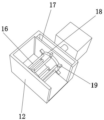
FIG. 4 is a schematic structural view of a burr collecting assembly of a deburring device for motor housing production according to the present invention;
FIG. 5 is a schematic structural view of a shell outer ring burr removing assembly of a burr removing device for motor shell production according to the present invention;
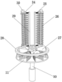
FIG. 6 is a schematic structural view of a housing inner ring burr removing assembly of a burr removing device for motor housing production according to the present invention;
FIG. 7 is a schematic structural view of a telescopic column assembly of a deburring device for motor housing production according to the present invention;
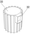
fig. 8 is a schematic view of a motor housing of a deburring device for motor housing production according to the present invention.
In the figure: 1-base, 2-support frame, 3-servo motor, 4-positive and negative screw rod, 5-cylinder I, 6-mounting frame, 7-sliding column, 8-containing frame, 9-moving plate, 10-cylinder II, 11-bottom brush disc, 12-collecting box, 13-exhaust fan, 14-rotating motor, 15-friction pressing plate, 16-adhesive paper winding column, 17-filter plate, 18-rotating disc, 19-wind deflector, 20-connecting rod, 21-tension spring, 22-rotating frame, 23-cylindrical air chamber box I, 24-hole type brush roller I, 25-spring, 26-hole type brush roller II, 27-circular table type rotating roller, 28-mounting disc, 29-straight plate, 30-cylindrical air chamber box II, 31-telescopic column, 32-junction box, 33-motor shell and 34-U-shaped frame.
Detailed Description
The technical solution of the present patent will be described in further detail with reference to the following embodiments.
Reference will now be made in detail to embodiments of the present patent, examples of which are illustrated in the accompanying drawings, wherein like or similar reference numerals refer to the same or similar elements or elements having the same or similar function throughout. The embodiments described below with reference to the drawings are exemplary only for the purpose of explaining the present patent and are not to be construed as limiting the present patent.
In the description of this patent, it is to be understood that the terms "center," "upper," "lower," "front," "rear," "left," "right," "vertical," "horizontal," "top," "bottom," "inner," "outer," and the like are used in the orientations and positional relationships indicated in the drawings for the convenience of describing the patent and for the simplicity of description, and are not intended to indicate or imply that the referenced devices or elements must have a particular orientation, be constructed and operated in a particular orientation, and are not to be considered limiting of the patent.
In the description of this patent, it is noted that unless otherwise specifically stated or limited, the terms "mounted," "connected," and "disposed" are to be construed broadly and can include, for example, fixedly connected, disposed, detachably connected, disposed, or integrally connected and disposed. The specific meaning of the above terms in this patent may be understood by those of ordinary skill in the art as appropriate.
A deburring device for motor shell production is shown in figures 1-5 and comprises a base 1, a motor shell 33 and a reverse distance adjusting mechanism, wherein the outer wall of the distance adjusting mechanism is connected with two moving plates 9 in a sliding mode, two rotating frames 22 are fixed on the inner walls of one sides of the two moving plates 9 through bolts, two connecting rods 20 are rotatably connected on the inner walls of the two rotating frames 22 through rotating shafts, one inner wall of one side of each of the two connecting rods 20 positioned on the same side is rotatably connected with a same hole-shaped hairbrush roller I24, and one outer wall of one side of each of the two connecting rods 20 positioned on two sides is connected with a same; can make two movable plates 9 carry out horizontal migration along opposite direction through being provided with reverse distance regulation structure, thereby can adjust the relative distance between two movable plates 9, through being provided with four pass brush rollers 24, can make its circumference outer wall can play the effect of centre gripping to motor housing 33 circumference outer wall at the in-process of movable plate 9 motion, thereby the brush that can make 24 circumference outer walls of pass brush roller set up can be got rid of the deckle edge of motor housing 33 circumference outer wall, utilize extension spring 21 can guarantee the laminating degree of brush and motor housing 33 circumference outer wall, make to have great frictional force between brush and the motor housing 33 circumference outer wall, thereby can guarantee the effect that deckle edge got rid of.
In order to adjust the distance between the two moving plates 9; as shown in fig. 1-2, the reverse distance adjusting mechanism includes a positive and negative lead screw 4 and a containing frame 8, the outer wall of the bottom of the containing frame 8 is fixed on the outer wall of the top of the base 1 through a bolt, the outer walls of both sides of the positive and negative lead screw 4 are respectively connected to the inner walls of both sides of the containing frame 8 through bearings in a rotating manner, the outer wall of one side of the containing frame 8 is fixed with a servo motor 3 through a bolt, the output end of the servo motor 3 is connected to the input end of the positive and negative lead screw 4 through a coupler, the inner walls of both sides of the containing frame 8 are fixed with two sliding columns 7 through bolts, and the outer walls of both the two; can drive positive and negative lead screw 4 through being provided with servo motor 3 and rotate, because positive and negative lead screw 4 is positive and negative thread structure, consequently can make between two movable plates 9 can be synchronous constant speed along opposite direction removal through positive and negative lead screw 4's rotation to can make a pass brush roller 24 laminate motor housing 33.
For placement of the motor housing 33; as shown in fig. 6, an air cylinder two 10 is fixed on the outer wall of the bottom of the base 1 through a bolt, the output end of the air cylinder two 10 is fixed with a bottom brush disc 11 through a bolt, the outer wall of the top of the bottom brush disc 11 is fixed with a mounting disc 28 through a bolt, the outer wall of the circumference of the mounting disc 28 is rotatably connected with more than two circular truncated cone-shaped rotating rollers 27, the outer wall of the top of the mounting disc 28 is fixed with two straight plates 29 through bolts, the outer wall of one side of each straight plate 29 is fixed with two telescopic columns 31 through bolts, one ends, far away from the straight plates 29, of the two telescopic columns 31 are fixed with a same U-shaped frame 34 through bolts, the outer wall of the circumference of each telescopic column 31 is slidably connected with a spring 25, two ends of each spring 25 are respectively clamped on the inner wall of the straight plate 29 and the inner wall of; more than two truncated cone-shaped rotating rollers 27 can be used for supporting and placing the bottom of the motor shell 33, meanwhile, the truncated cone-shaped rotating rollers 27 are in a truncated cone structure, the bottom of the motor shell 33 can rotate along the outer wall of the truncated cone-shaped rotating rollers 27, burrs on the outer wall of the bottom of the motor shell 33 can be removed in the rotating process of the motor shell 33 by arranging the bottom brush disk 11, the cleaning dead angle is reduced, meanwhile, the inner wall of the circumference of the motor shell 33 can be sleeved and connected with the inner wall of the circumference of the motor shell 33 by arranging the hole-shaped brush rollers two 26, so that the inner wall of the circumference of the motor shell 33 can be subjected to burr removing treatment, and due to the difference of the specifications of the inner diameters of the motor shell 33, the outer wall of the circumference of the hole-shaped brush rollers two 26 can be tightly attached to the inner wall of the circumference of the motor shell 33 by utilizing the, meanwhile, the height of the mounting plate 28 can be adjusted by using the second air cylinder 10, so that the motor shell 33 can be conveniently taken and placed.
To rotate the motor housing 33; as shown in fig. 1 and 3, a support frame 2 is fixed on the outer wall of the top of a base 1 through bolts, a first air cylinder 5 is fixed on the outer wall of the top of the support frame 2 through bolts, an installation frame 6 is fixed on the output end of the first air cylinder 5 through bolts, a rotating motor 14 is fixed on the inner wall of the bottom of the installation frame 6 through bolts, and a friction pressing plate 15 is fixed on the output shaft of the rotating motor 14 through bolts; the accommodating frame 8 can be driven to move downwards by the first air cylinder 5, so that the friction pressing plate 15 can be pressed on the outer wall of the top of the motor shell 33, the outer wall of the bottom of the friction pressing plate 15 is of a concave-convex structure, the friction force between the outer wall of the top of the motor shell 33 can be improved, meanwhile, the friction pressing plate 15 can be driven to rotate by the rotating motor 14, the bottom of the motor shell 33 can synchronously rotate by the circular table type rotating rollers 27, meanwhile, because the height of the hole type brush rollers two 26 is fixed and the height of the motor shell 33 is different, the friction pressing plate 15 is of a hollow structure, the friction pressing plate 15 can penetrate through the hole type brush rollers two 26, so that the outer wall of the bottom of the friction pressing plate 15 is pressed and fixed on the outer wall of the top of the motor shell 33, the outer wall of the circumference of the motor shell 33 can generate friction force with the hole type brush rollers one 24, thereby can guarantee that the different positions on the surface of a pass brush roller 24 can carry out unhairing limit to motor housing 33 circumference outer wall and handle, utilize rotating electrical machines 14 to drive friction clamp plate 15 simultaneously and be clockwise and anticlockwise's step motion to can make friction clamp plate 15 drive motor housing 33 and carry out just reversing in the within range of injecing of friction clamp plate 15, thereby can utilize the just reversing of friction clamp plate 15 to guarantee the efficiency of unhairing limit.
To avoid the appearance of cleaning dead corners; as shown in fig. 8, a junction box 32 is welded to the circumferential outer wall of the motor housing 33; because motor housing 33 is not pure cylindricality structure, its circumference outer wall can be provided with terminal box 32 and be used for laying wire, consequently when the outer wall of a pass brush roller 24 circumference is to terminal box 32 unhairing limit, can lead to a pass brush roller 24 can't cover the cambered surface position of motor housing 33 in the terminal box 32 bottom completely, utilize the up-and-down motion of cylinder 5 and cylinder two 10, can make terminal box 32 department remove to the bottom of a pass brush roller 24, thereby make a pass brush roller 24 carry out unhairing limit to the cambered surface position of terminal box 32 bottom, pass the back in following friction clamp plate 15 when pass as pass of pass brush roller two 26 simultaneously, can utilize pass brush roller two 26 to unhairing limit to motor housing 33 top outer wall, guarantee can not have and clear away the dead angle.
In order to collect burrs; as shown in fig. 2 and 4, a collection box 12 and an exhaust fan 13 are fixed on the outer wall of the top of the support frame 2 through bolts, the output end of the exhaust fan 13 is connected to the outer wall of one side of the collection box 12 through a pipeline, the inner walls of two sides of the collection box 12 are fixed with a same filter plate 17 through bolts, the inner walls of two sides of the collection box 12 are rotatably connected with rotating discs 18 through rotating shafts, more than two sticky paper winding columns 16 are welded on the outer wall of one side of each of the two rotating discs 18, more than two air deflectors 19 are welded on the outer wall of the circumference of each of the rotating discs 18, a cylindrical air chamber box 23 and a cylindrical air chamber box 30 are respectively fixed on the outer wall of the top of the hole type brush roller one 24 and the outer wall of the top of the hole type brush roller two 26 through; the first hole type brush roller 24 and the second hole type brush roller 26 are both of a hollow structure, the outer walls of the circumferences of the first hole type brush roller 24 and the second hole type brush roller 26 are provided with leaking holes, the exhaust fan 13 can be used for exhausting air inside the collection box 12, so that the inside of the collection box 12 can be in a negative pressure condition, the first hole type brush roller 24 and the truncated cone type rotating roller 27 can absorb burrs after being removed through the leaking holes, the burrs can be guided into the collection box 12 through a pipeline, the first hole type brush roller 24 is rotationally connected to the inner wall of the connecting rod 20, the second hole type brush roller 26 is rotationally connected to the inner wall of the U-shaped frame 34, the first cylindrical air chamber box 23 and the second cylindrical air chamber box 30 can be used as a medium, the burrs can be smoothly guided into the collection box 12, meanwhile, the burrs are small in particles, sticky paper can be used for winding sticky, thereby reduce the adhering to of deckle edge to collecting box 12 inner wall, be convenient for clear up collecting box 12, because there is stronger air current in the inside of collecting box 12, the air current can stir aviation baffle 19 and make aviation baffle 19 can drive rolling disc 18 and rotate to can guarantee that each position on adhesive paper surface can better collect the deckle edge, utilize filter plate 17 to filter the wind gap of air exhauster 13 simultaneously, avoid the deckle edge to take place to spill over.
When the embodiment is used, when burrs on the surface of the motor housing 33 need to be processed, firstly, according to the inner diameter of the motor housing 33, the circumferential outer wall of the two hole-shaped brush rolls 26 is attached to the circumferential inner wall of the motor housing 33 under the action of the springs 25, then, the outer wall of the bottom of the motor housing 33 is placed on the surface of the circular truncated cone-shaped rotating roll 27 in a sliding manner, then, the height of the mounting disc 28 is adjusted by using the air cylinders 10, so that brushes on the circumferential outer wall of the hole-shaped brush rolls 26 can accommodate the circumferential outer wall of the motor housing 33, then, the distance between the two moving plates 9 is adjusted by using the servo motor 3, so that the circumferential outer wall of the hole-shaped brush rolls 24 can be attached to the circumferential outer wall of the motor housing 33, then, the air cylinders 5 are used for driving the friction pressing plate 15 to move downwards, and due to the tension effect of the tension springs, make two pass brush roller two 26 pass the clearance in the friction clamp plate 15, rotating electrical machines 14 drives the clockwise and anticlockwise motion that friction clamp plate 15 does certain angle next, utilize friction clamp plate 15 to drive motor housing 33 and rotate, pass brush roller one 24 clears up the deckle edge of motor housing 33 circumference outer wall under the effect of frictional force at motor housing 33 pivoted in-process, simultaneously because straight board 29 fixed mounting, consequently can make pass brush roller two 26 rotate along motor housing 33 circumference inner wall, thereby can carry out deckle edge processing to motor housing 33 circumference inner wall, utilize bottom brush dish 11 to carry out deckle edge processing to motor housing 33 bottom simultaneously, utilize pass brush roller two 26 to carry out deckle edge processing to motor housing 33 top outer wall, guarantee that there is not the clearance dead angle, can make pass brush roller one 24 to go up the motor housing 33 cambered surface part of line box 32 department and bottom through the height of control mounting disc 28 and clear up the deckle edge and clear up the clearance of motor housing 33 cambered surface part of line box 32 department The in-process of unhairing limit utilizes collecting box 12 and air exhauster 13 can be collected deckle edge to make deckle edge adsorb on the adhesive paper of 16 circumference outer walls of adhesive paper winding post, can collect deckle edge, the operation finishes the back and takes off motor housing 33 can.
The above description is only for the preferred embodiment of the present invention, but the scope of the present invention is not limited thereto, and any person skilled in the art should be considered to be within the technical scope of the present invention, and the technical solutions and the inventive concepts thereof according to the present invention should be equivalent or changed within the scope of the present invention.
Claims (10)
1. The utility model provides a deckle edge device is used in motor housing production, includes base (1), motor housing (33) and reverse distance adjustment mechanism, a serial communication port, there are two movable plates (9), two apart from adjustment mechanism outer wall sliding connection movable plate (9) one side inner wall all has two rotating turret (22), two through the bolt fastening rotating turret (22) inner wall all is connected with two connecting rods (20) through the pivot rotation, and two connecting rods (20) that are located the homonymy one side inner wall rotates and is connected with same pass brush roller (24), and two connecting rods (20) that are located both sides one side outer wall joint has same extension spring (21).
2. The deburring device for motor housing production according to claim 1, wherein the reverse distance adjusting mechanism comprises a positive and negative lead screw (4) and a containing frame (8), the outer wall of the bottom of the containing frame (8) is fixed on the outer wall of the top of the base (1) through a bolt, the outer walls of two sides of the positive and negative lead screw (4) are respectively connected with the inner walls of two sides of the containing frame (8) through a bearing in a rotating manner, the outer wall of one side of the containing frame (8) is fixed with a servo motor (3) through a bolt, and the output end of the servo motor (3) is connected with the input end of the positive and negative lead screw (4) through a coupling.
3. The deburring device for motor housing production according to claim 2, wherein two sliding columns (7) are fixed on the inner walls of two sides of the containing frame (8) through bolts, and the outer walls of the two moving plates (9) are both connected with the circumferential outer walls of the two sliding columns (7) in a sliding manner.
4. The de-burring device for motor housing production according to claim 3, characterized in that the outer wall of the bottom of the base (1) is fixed with a second cylinder (10) by bolts, the output end of the second cylinder (10) is fixed with a bottom brush plate (11) by bolts, the outer wall of the top of the bottom brush plate (11) is fixed with a mounting plate (28) by bolts, the outer wall of the circumference of the mounting plate (28) is rotatably connected with more than two rotary rollers (27) in the shape of a circular truncated cone, the outer wall of the top of the mounting plate (28) is fixed with two straight plates (29) by bolts, and the outer wall of one side of each straight plate (29) is fixed with two telescopic columns (31) by bolts.
5. The deburring device for motor housing production according to claim 4, wherein one end of each of the two telescopic columns (31) far away from the straight plate (29) is fixed with a U-shaped frame (34) through a bolt, the outer wall of the circumference of each telescopic column (31) is slidably connected with a spring (25), two ends of each spring (25) are respectively clamped on the primary inner wall of the straight plate (29) and the primary inner wall of the U-shaped frame (34), and the inner wall of each U-shaped frame (34) is rotatably connected with a second hole-shaped brush roller (26).
6. The de-burring device for motor housing production according to claim 5, characterized in that the outer wall of the top of the base (1) is fixed with the support frame (2) by bolts, the outer wall of the top of the support frame (2) is fixed with the first cylinder (5) by bolts, the output end of the first cylinder (5) is fixed with the mounting frame (6) by bolts, the inner wall of the bottom of the mounting frame (6) is fixed with the rotating motor (14) by bolts, and the output shaft of the rotating motor (14) is fixed with the friction pressing plate (15) by bolts.
7. The de-burring device for motor housing production as claimed in claim 6, characterized in that the terminal box (32) is welded to the circumferential outer wall of the motor housing (33).
8. The deburring device for motor housing production according to claim 7, wherein the outer wall of the top of the support frame (2) is fixed with a collection box (12) and an exhaust fan (13) through bolts, the output end of the exhaust fan (13) is connected with the outer wall of one side of the collection box (12) through a pipeline, the inner walls of two sides of the collection box (12) are fixed with the same filter plate (17) through bolts, and the inner walls of two sides of the collection box (12) are rotatably connected with a rotating disc (18) through rotating shafts.
9. The de-burring device for the production of motor housings as claimed in claim 8, wherein more than two adhesive paper winding columns (16) are welded on the outer wall of one side of the two rotating disks (18), and more than two air deflectors (19) are welded on the outer wall of the circumference of the rotating disks (18).
10. The deburring device for motor housing production according to claim 9, wherein the outer wall of the top of the first hole type brush roller (24) and the outer wall of the top of the second hole type brush roller (26) are respectively fixed with a first cylindrical air chamber box (23) and a second cylindrical air chamber box (30) through bolts, and the outer wall of the collection box (12) is respectively connected to the outer wall of the top of the first cylindrical air chamber box (23) and the outer wall of the top of the second cylindrical air chamber box (30) through pipelines.
Priority Applications (1)
| Application Number | Priority Date | Filing Date | Title |
|---|---|---|---|
| CN202011434408.1A CN112405196A (en) | 2020-12-10 | 2020-12-10 | Deburring device for motor housing production |
Applications Claiming Priority (1)
| Application Number | Priority Date | Filing Date | Title |
|---|---|---|---|
| CN202011434408.1A CN112405196A (en) | 2020-12-10 | 2020-12-10 | Deburring device for motor housing production |
Publications (1)
| Publication Number | Publication Date |
|---|---|
| CN112405196A true CN112405196A (en) | 2021-02-26 |
Family
ID=74775420
Family Applications (1)
| Application Number | Title | Priority Date | Filing Date |
|---|---|---|---|
| CN202011434408.1A Withdrawn CN112405196A (en) | 2020-12-10 | 2020-12-10 | Deburring device for motor housing production |
Country Status (1)
| Country | Link |
|---|---|
| CN (1) | CN112405196A (en) |
Cited By (8)
| Publication number | Priority date | Publication date | Assignee | Title |
|---|---|---|---|---|
| CN113427371A (en) * | 2021-07-01 | 2021-09-24 | 安徽亚太锚链制造有限公司 | Anchor chain manufacturing and processing device with automatic flushing function |
| CN113878431A (en) * | 2021-09-10 | 2022-01-04 | 安徽省巢湖市宏顺机械铸造有限公司 | High-efficient grinding device is used in production of machinery foundry goods |
| CN114131450A (en) * | 2021-12-22 | 2022-03-04 | 江苏鑫沪莱泵业有限公司 | A burr remove device for suction pump production and processing usefulness |
| CN114227542A (en) * | 2021-12-27 | 2022-03-25 | 徐州智奇机械科技有限公司 | Plastic shell deburring and trimming equipment for manufacturing electronic products |
| CN115431127A (en) * | 2022-09-19 | 2022-12-06 | 徐州康翔精密制造有限公司 | Motor protective shell inner wall burr removing equipment |
| CN115958427A (en) * | 2023-02-13 | 2023-04-14 | 苏州市豪致达精密机械有限公司 | Numerical control machine tool equipment for machining motor shell |
| CN118543911A (en) * | 2024-07-30 | 2024-08-27 | 江苏百固工程机械部件制造有限公司 | Screw thread grinding device is used in fastener processing |
| CN122184946A (en) * | 2026-05-18 | 2026-06-12 | 新昌县兆阳机械有限公司 | Bearing inner race processingequipment |
Citations (9)
| Publication number | Priority date | Publication date | Assignee | Title |
|---|---|---|---|---|
| JP2014083639A (en) * | 2012-10-24 | 2014-05-12 | Bridge Engineering:Kk | Surface preparation tool for bolt and nut |
| CN206998562U (en) * | 2017-07-21 | 2018-02-13 | 湖南盛华源材料科技有限公司 | A kind of brush skin machine of coloured solder production |
| CN207593413U (en) * | 2017-11-15 | 2018-07-10 | 青岛嘉和鑫钢铁有限公司 | A kind of mechanical automation steel pipe synchronizes rust removalling equipment |
| CN108527107A (en) * | 2018-03-26 | 2018-09-14 | 湖州弘盛消防设备有限公司 | A kind of fire-fighting box enclosure polishing derusting device |
| CN110480445A (en) * | 2019-08-21 | 2019-11-22 | 马鞍山常裕机械设备有限公司 | A deburring device for a steering motor housing that prevents scratches |
| CN210081415U (en) * | 2019-06-19 | 2020-02-18 | 博农联合技术(天津)有限公司 | Rust removal device for steel pipe machining |
| CN210731960U (en) * | 2019-10-12 | 2020-06-12 | 合肥达力机械制造有限公司 | Deburring device for flywheel casting |
| CN211136684U (en) * | 2019-08-12 | 2020-07-31 | 合肥鑫鼎机械电子有限公司 | A rust removal device for processing electromechanical products |
| CN112008575A (en) * | 2020-09-05 | 2020-12-01 | 王金莲 | Rust removal equipment for steel pipe machining in building engineering field |
-
2020
- 2020-12-10 CN CN202011434408.1A patent/CN112405196A/en not_active Withdrawn
Patent Citations (9)
| Publication number | Priority date | Publication date | Assignee | Title |
|---|---|---|---|---|
| JP2014083639A (en) * | 2012-10-24 | 2014-05-12 | Bridge Engineering:Kk | Surface preparation tool for bolt and nut |
| CN206998562U (en) * | 2017-07-21 | 2018-02-13 | 湖南盛华源材料科技有限公司 | A kind of brush skin machine of coloured solder production |
| CN207593413U (en) * | 2017-11-15 | 2018-07-10 | 青岛嘉和鑫钢铁有限公司 | A kind of mechanical automation steel pipe synchronizes rust removalling equipment |
| CN108527107A (en) * | 2018-03-26 | 2018-09-14 | 湖州弘盛消防设备有限公司 | A kind of fire-fighting box enclosure polishing derusting device |
| CN210081415U (en) * | 2019-06-19 | 2020-02-18 | 博农联合技术(天津)有限公司 | Rust removal device for steel pipe machining |
| CN211136684U (en) * | 2019-08-12 | 2020-07-31 | 合肥鑫鼎机械电子有限公司 | A rust removal device for processing electromechanical products |
| CN110480445A (en) * | 2019-08-21 | 2019-11-22 | 马鞍山常裕机械设备有限公司 | A deburring device for a steering motor housing that prevents scratches |
| CN210731960U (en) * | 2019-10-12 | 2020-06-12 | 合肥达力机械制造有限公司 | Deburring device for flywheel casting |
| CN112008575A (en) * | 2020-09-05 | 2020-12-01 | 王金莲 | Rust removal equipment for steel pipe machining in building engineering field |
Cited By (12)
| Publication number | Priority date | Publication date | Assignee | Title |
|---|---|---|---|---|
| CN113427371A (en) * | 2021-07-01 | 2021-09-24 | 安徽亚太锚链制造有限公司 | Anchor chain manufacturing and processing device with automatic flushing function |
| CN113427371B (en) * | 2021-07-01 | 2023-01-10 | 安徽亚太锚链制造有限公司 | Anchor chain manufacturing and processing device with automatic flushing function |
| CN113878431A (en) * | 2021-09-10 | 2022-01-04 | 安徽省巢湖市宏顺机械铸造有限公司 | High-efficient grinding device is used in production of machinery foundry goods |
| CN114131450A (en) * | 2021-12-22 | 2022-03-04 | 江苏鑫沪莱泵业有限公司 | A burr remove device for suction pump production and processing usefulness |
| CN114227542A (en) * | 2021-12-27 | 2022-03-25 | 徐州智奇机械科技有限公司 | Plastic shell deburring and trimming equipment for manufacturing electronic products |
| CN115431127A (en) * | 2022-09-19 | 2022-12-06 | 徐州康翔精密制造有限公司 | Motor protective shell inner wall burr removing equipment |
| CN115431127B (en) * | 2022-09-19 | 2023-11-03 | 徐州康翔精密制造有限公司 | A device for removing burrs on the inner wall of motor housings |
| CN115958427A (en) * | 2023-02-13 | 2023-04-14 | 苏州市豪致达精密机械有限公司 | Numerical control machine tool equipment for machining motor shell |
| CN115958427B (en) * | 2023-02-13 | 2023-09-01 | 苏州市豪致达精密机械有限公司 | Numerical control machine tool equipment for machining motor shell |
| CN118543911A (en) * | 2024-07-30 | 2024-08-27 | 江苏百固工程机械部件制造有限公司 | Screw thread grinding device is used in fastener processing |
| CN118543911B (en) * | 2024-07-30 | 2024-10-08 | 江苏百固工程机械部件制造有限公司 | Screw thread grinding device is used in fastener processing |
| CN122184946A (en) * | 2026-05-18 | 2026-06-12 | 新昌县兆阳机械有限公司 | Bearing inner race processingequipment |
Similar Documents
| Publication | Publication Date | Title |
|---|---|---|
| CN220825185U (en) | Cleaning device and pole piece processing equipment with same | |
| CN112077036B (en) | New forms of energy dust collector | |
| CN118143836B (en) | Intelligent control polishing machine tool | |
| CN211219204U (en) | Graphene pole piece processing device for lithium battery | |
| CN114145359A (en) | Tea leaf drying device with tea hair collecting mechanism | |
| CN221274862U (en) | Cable winding equipment | |
| CN219560563U (en) | Intelligent hot-rolled steel plate surface dust removing device | |
| CN219881619U (en) | Welding device with slag cleaning function | |
| CN118060072A (en) | Electric dust remover for powder bin production | |
| CN212069621U (en) | Machining dust collector | |
| CN213474857U (en) | PVDF film coiling mechanism | |
| CN212468969U (en) | Photovoltaic module self-cleaning device | |
| CN213558864U (en) | Power equipment dust removal case | |
| CN212953311U (en) | Winding and collecting equipment for processing bed sheet cloth | |
| CN223863520U (en) | Polishing device for pin production | |
| CN217369562U (en) | Dust collector for cable processing | |
| CN222789901U (en) | A surface dust removal machine for PE film production | |
| CN222175221U (en) | A dust removal device for automobile parts production and processing | |
| CN216720559U (en) | Power distribution station direct current screen device with automatic dust removal mechanism | |
| CN221777153U (en) | A PETG decorative film winding device | |
| CN220866668U (en) | Protective film rolling static-removing mechanism | |
| CN215942379U (en) | Motor housing burring device | |
| CN117760029B (en) | Evaporative wet curtain dust removal and cleaning equipment for evaporative environmentally friendly air conditioners | |
| CN223802218U (en) | Trimming device for hub machining | |
| CN220590438U (en) | Efficient double-colored reciprocating engine |
Legal Events
| Date | Code | Title | Description |
|---|---|---|---|
| PB01 | Publication | ||
| PB01 | Publication | ||
| SE01 | Entry into force of request for substantive examination | ||
| SE01 | Entry into force of request for substantive examination | ||
| WW01 | Invention patent application withdrawn after publication |
Application publication date: 20210226 |
|
| WW01 | Invention patent application withdrawn after publication |