CN112402032A - Head fixing device for ophthalmic therapy - Google Patents
Head fixing device for ophthalmic therapy Download PDFInfo
- Publication number
- CN112402032A CN112402032A CN202011392454.XA CN202011392454A CN112402032A CN 112402032 A CN112402032 A CN 112402032A CN 202011392454 A CN202011392454 A CN 202011392454A CN 112402032 A CN112402032 A CN 112402032A
- Authority
- CN
- China
- Prior art keywords
- wall
- head
- fixing
- supporting plate
- plate
- Prior art date
- Legal status (The legal status is an assumption and is not a legal conclusion. Google has not performed a legal analysis and makes no representation as to the accuracy of the status listed.)
- Withdrawn
Links
Images


Classifications
-
- A—HUMAN NECESSITIES
- A61—MEDICAL OR VETERINARY SCIENCE; HYGIENE
- A61B—DIAGNOSIS; SURGERY; IDENTIFICATION
- A61B90/00—Instruments, implements or accessories specially adapted for surgery or diagnosis and not covered by any of the groups A61B1/00 - A61B50/00, e.g. for luxation treatment or for protecting wound edges
- A61B90/10—Instruments, implements or accessories specially adapted for surgery or diagnosis and not covered by any of the groups A61B1/00 - A61B50/00, e.g. for luxation treatment or for protecting wound edges for stereotaxic surgery, e.g. frame-based stereotaxis
- A61B90/14—Fixators for body parts, e.g. skull clamps; Constructional details of fixators, e.g. pins
-
- A—HUMAN NECESSITIES
- A61—MEDICAL OR VETERINARY SCIENCE; HYGIENE
- A61B—DIAGNOSIS; SURGERY; IDENTIFICATION
- A61B3/00—Apparatus for testing the eyes; Instruments for examining the eyes
- A61B3/0008—Apparatus for testing the eyes; Instruments for examining the eyes provided with illuminating means
-
- A—HUMAN NECESSITIES
- A61—MEDICAL OR VETERINARY SCIENCE; HYGIENE
- A61B—DIAGNOSIS; SURGERY; IDENTIFICATION
- A61B3/00—Apparatus for testing the eyes; Instruments for examining the eyes
- A61B3/0083—Apparatus for testing the eyes; Instruments for examining the eyes provided with means for patient positioning
-
- A—HUMAN NECESSITIES
- A61—MEDICAL OR VETERINARY SCIENCE; HYGIENE
- A61B—DIAGNOSIS; SURGERY; IDENTIFICATION
- A61B90/00—Instruments, implements or accessories specially adapted for surgery or diagnosis and not covered by any of the groups A61B1/00 - A61B50/00, e.g. for luxation treatment or for protecting wound edges
- A61B90/10—Instruments, implements or accessories specially adapted for surgery or diagnosis and not covered by any of the groups A61B1/00 - A61B50/00, e.g. for luxation treatment or for protecting wound edges for stereotaxic surgery, e.g. frame-based stereotaxis
- A61B90/14—Fixators for body parts, e.g. skull clamps; Constructional details of fixators, e.g. pins
- A61B90/17—Fixators for body parts, e.g. skull clamps; Constructional details of fixators, e.g. pins for soft tissue, e.g. breast-holding devices
Abstract
The invention discloses a head fixing device for ophthalmic treatment, and relates to the technical field of ophthalmic treatment; the problem that a doctor cannot conveniently diagnose and treat the eyes of a patient is solved; this device specifically includes the carriage, the carriage outer wall is provided with two flexible bracing pieces respectively, and carriage top inner wall is provided with the backup pad, and backup pad bottom outer wall is provided with head fixture, and backup pad bottom outer wall sliding connection has the installation piece, and installation piece bottom outer wall sliding connection has two installation poles respectively, and installation pole one side outer wall sliding connection has the fixed frame of eyelid, and the fixed frame top of eyelid and bottom outer wall are opened respectively has two circular through-holes. According to the invention, the second fixing piece and the first fixing piece are arranged, the mounting piece can slide on the outer wall of the bottom of the supporting plate, the distance between the eyelid fixing frame and the eyes of a patient can be adjusted, and the second fixing piece can be fixed through the screw after the adjustment is finished, so that the position of the mounting piece is fixed.
Description
Technical Field
The invention relates to the technical field of ophthalmic treatment, in particular to a head fixing device based on ophthalmic treatment.
Background
The ophthalmology is called as 'ophthalmology specialty', which is a discipline for researching diseases related to eyeballs and tissues related to the eyeballs, the ophthalmology generally researches vitreous bodies, retina diseases, ocular optics, glaucoma, optic neuropathy, cataract and other ophthalmic diseases, the general examination of eyes comprises eye attachments and anterior segment examination, the eye attachments examination comprises the examination of eyelids, conjunctiva, lacrimal apparatus, eyeball positions and eye sockets, the ophthalmic examination is an important component in the physical examination, the most common problem in young people is ametropia, the head of a patient is difficult to match with a doctor during the treatment due to visual stimulation during the ophthalmic treatment, so that the head of the patient needs to be fixed to determine that the doctor can better treat the patient, while the existing treatment beds for the ophthalmic treatment patients generally do not have the function of head fixing or the function of fixing is single, the adjustment is not easy, which brings inconvenience to the treatment of doctors.
Through retrieval, chinese patent application No. CN211094799U discloses a head fixing device for ophthalmic therapy, which includes a first connecting column, a first connecting block is fixedly connected to the bottom of the first connecting column, a lead screw is inserted into the right side of the first connecting block, and a first moving block is movably connected to the left side of the outer side surface of the lead screw.
Disclosure of Invention
The invention aims to solve the defects in the prior art and provides a head fixing device for ophthalmic treatment.
In order to achieve the purpose, the invention adopts the following technical scheme:
the utility model provides a head fixing device for based on ophthalmic therapy, including the carriage, the carriage outer wall is provided with two flexible bracing pieces respectively, carriage top inner wall is provided with the backup pad, backup pad bottom outer wall is provided with head fixture, backup pad bottom outer wall sliding connection has the installation piece, installation piece bottom outer wall sliding connection has two installation poles respectively, installation pole one side outer wall sliding connection has the fixed frame of eyelid, the fixed frame top of eyelid and bottom outer wall are opened respectively has two circular through-holes, two circular through-hole inner walls have two screw thread knobs through the thread tightening respectively, two screw thread knob one side outer walls rotate through rolling bearing respectively and are connected with two eyelid hooks, carriage bottom inner wall is provided with chin bar.
Preferably: the outer wall of one side of the installation block is provided with two second fixing pieces respectively, the two second fixing pieces are fixed on the outer wall of the bottom of the supporting plate through screws respectively, the outer wall of one side of the two installation rods is provided with two first fixing pieces respectively, the two first fixing pieces are fixed on the outer wall of one side of the installation block through screws respectively, and the outer wall of one side of the eyelid fixing frame is fixed on the outer wall of one side of the installation rod through screws respectively.
Further: head fixed establishment includes two cheek fixed plates, two connecting rods, two sliding blocks and hindbrain guard plate, and two cheek fixed plate top outer walls set up respectively on the bottom outer wall of backup pad, and two sliding blocks sliding connection respectively are on the both sides outer wall of backup pad, and the top outer wall of two sliding blocks is respectively through the screw fixation on the top outer wall of backup pad, and two connecting rods set up respectively on one side outer wall of two sliding blocks, and hindbrain guard plate both sides outer wall sets up respectively on one side outer wall of two connecting rods.
Further preferred is: the outer wall of backup pad bottom sliding connection has two slides respectively, and two slides are fixed in on the bottom outer wall of backup pad through the screw respectively, and slide bottom outer wall is provided with three flexible dead lever respectively, and the cheek fixed plate sets up on the bottom outer wall of three flexible dead lever, and cheek fixed plate one side outer wall is provided with two buffer blocks respectively, and the buffer block is made by elastic sponge.
As a preferable aspect of the present invention: the outer wall of the bottom of the supporting plate is provided with a head limiting groove, and the inner wall of the head limiting groove is provided with a layer of elastic sponge.
Further preferred as the invention: the outer wall of one side of the supporting plate is connected with a second connecting block in a sliding mode, the outer wall of one side of the second connecting block is provided with a second damping rotating shaft, the outer wall of one side of the second damping rotating shaft is provided with a first connecting block, and the outer wall of one side of the first connecting block is provided with a lighting lamp.
As a still further scheme of the invention: two outer walls of one side of the two telescopic supporting rods are respectively provided with two handles.
On the basis of the scheme: the supporting frame both sides outer wall is provided with two rolling discs respectively, and the cotter hole more than three is opened respectively to rolling disc one side outer wall, and two flexible bracing piece one side outer walls branch is provided with two spacers, and the cotter hole more than three is opened respectively to spacer one side outer wall, and spacer one side outer wall is provided with first damping pivot, and first damping pivot one side outer wall sets up on one side outer wall of rolling disc, and the spacer is fixed in on one side outer wall of rolling disc through the pin respectively.
On the basis of the foregoing scheme, it is preferable that: the inner wall of the top of the supporting frame is provided with a third damping rotating shaft, the outer wall of the bottom of the third damping rotating shaft is provided with a supporting plate, more than three pin holes are formed in the outer wall of the top of the supporting plate respectively, and the supporting frame is fixed on the outer wall of the top of the supporting plate through two second pins respectively.
The invention has the beneficial effects that:
1. through setting up second stationary blade and first stationary blade, the installation piece can slide at backup pad bottom outer wall, can adjust the distance of the fixed frame of eyelid and patient's eye, can fix the second stationary blade through the screw after the adjustment is accomplished, thereby fix the position of installation piece, the installation pole can slide on the installation piece, can adjust the distance between the fixed frame of two eyelids, use the screw to fix the installation pole on one side outer wall of first stationary blade simultaneously, can accomplish the fixed to the installation pole position, the fixed frame of eyelid can reciprocate through the installation pole simultaneously, thereby let the position of the fixed frame of two eyelids can both adjust, can carry out the eyelid to the head of equidimension not fixed.
2. Through setting up hind brain guard plate, sliding block and cheek fixed plate, two cheek fixed plates can effectively fix patient's cheek, let patient's head rock about can't be random, and the hind brain guard plate can be fixed patient's hind brain simultaneously to rock around letting patient's head can't be random, can adjust the position of hind brain guard plate through the sliding block, let the hind brain guard plate can fix the head of equidimension not.
3. Through setting up the slide, flexible dead lever and buffer block, the slide can slide at backup pad bottom outer wall to distance between two cheek fixed plates of adjustment that can be convenient also can adjust the height of cheek fixed plate through flexible dead lever, thereby lets the cheek fixed plate can fix the head of equidimension not, and the buffer block can play fine cushioning effect to patient's cheek simultaneously.
4. Through setting up second connecting block, second damping pivot and light, the light can provide powerful light source for the doctor when diagnosing, and the doctor can adjust the last small-angle of light through second damping pivot, also can adjust the position about the light through the second connecting block simultaneously, lets the light can diagnose with angle help doctor better.
5. By arranging the first damping rotating shaft, the positioning piece and the rotating disc, the supporting frame can rotate in an up-and-down angle through the first damping rotating shaft, so that a doctor can adjust the up-and-down angle of the head of a patient, the doctor can better treat the eyes of the patient, and the position between the positioning piece and the rotating disc can be fixed by the first pin after the proper angle is adjusted; through setting up third damping pivot, can let the backup pad carry out the removal of controlling the angle to let the doctor can carry out effective adjustment to the angle about patient's head.
Drawings
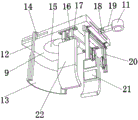
Fig. 1 is a front view schematically illustrating a head fixing device for ophthalmic treatment according to the present invention;
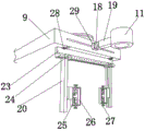
FIG. 2 is a schematic side view of a head fixation device for ophthalmic treatment according to the present invention;
FIG. 3 is a schematic top view of a head fixation device for ophthalmic treatment according to the present invention;
FIG. 4 is a side view of a head fixation device for ophthalmic treatment according to the present invention;
FIG. 5 is a schematic structural view of a head fixing mechanism based on a head fixing device for ophthalmic treatment according to the present invention;
fig. 6 is a schematic structural view of an eyelid holding mechanism based on a head fixing device for ophthalmic treatment according to the present invention.
In the figure: 1 carriage, 2 rolling discs, 3 flexible bracing pieces, 4 handles, 5 chin rests, 6 first pins, 7 spacer plates, 8 first damping pivot, 9 backup pads, 10 second pins, 11 light, 12 connecting rods, 13 hind brain protection board, 14 sliding blocks, 15 head spacing recesses, 16 flexible dead lever, 17 sliding plates, 18 second damping pivot, 19 first connecting blocks, 20 installation poles, 21 buffer blocks, 22 cheek fixed plates, 23 installation blocks, 24 first fixing plates, 25 eyelids hook, 26 eyelids fixed frame, 27 screw knob, 28 second fixing plates, 29 second connecting blocks, 30 third damping pivot.
Detailed Description
The technical solution of the present patent will be described in further detail with reference to the following embodiments.
Reference will now be made in detail to embodiments of the present patent, examples of which are illustrated in the accompanying drawings, wherein like or similar reference numerals refer to the same or similar elements or elements having the same or similar function throughout. The embodiments described below with reference to the drawings are exemplary only for the purpose of explaining the present patent and are not to be construed as limiting the present patent.
In the description of this patent, it is to be understood that the terms "center," "upper," "lower," "front," "rear," "left," "right," "vertical," "horizontal," "top," "bottom," "inner," "outer," and the like are used in the orientations and positional relationships indicated in the drawings for the convenience of describing the patent and for the simplicity of description, and are not intended to indicate or imply that the referenced devices or elements must have a particular orientation, be constructed and operated in a particular orientation, and are not to be considered limiting of the patent.
In the description of this patent, it is noted that unless otherwise specifically stated or limited, the terms "mounted," "connected," and "disposed" are to be construed broadly and can include, for example, fixedly connected, disposed, detachably connected, disposed, or integrally connected and disposed. The specific meaning of the above terms in this patent may be understood by those of ordinary skill in the art as appropriate.
The utility model provides a head fixing device for based on ophthalmic therapy, as shown in fig. 1-6, including carriage 1, 1 outer wall of carriage is provided with two flexible bracing pieces 3 respectively, 1 top inner wall of carriage is provided with backup pad 9, 9 bottom outer walls of backup pad are provided with head fixture, 9 bottom outer walls of backup pad have an installation piece 23, 23 bottom outer walls of installation piece have two installation poles 20 of sliding connection respectively, the fixed frame 26 of eyelid of outer wall sliding connection in installation pole 20 one side, fixed frame 26 top of eyelid and bottom outer wall are opened respectively has two circular through-holes, two circular through-hole inner walls are fixed with two screw knobs 27 through the screw thread respectively, two screw knobs 27 one side outer walls rotate through rolling bearing respectively and are connected with two eyelid hooks 25, 1 bottom inner wall of carriage is provided with chin strap 5.
In order to be able to adjust the position of the two eyelid holding frames 26; as shown in fig. 6, the outer wall of one side of the mounting block 23 is respectively provided with two second fixing pieces 28, the two second fixing pieces 28 are respectively fixed on the outer wall of the bottom of the supporting plate 9 through screws, the outer wall of one side of the two mounting rods 20 is respectively provided with two first fixing pieces 24, the two first fixing pieces 24 are respectively fixed on the outer wall of one side of the mounting block 23 through screws, and the outer wall of one side of the eyelid fixing frame 26 is respectively fixed on the outer wall of one side of the mounting rod 20 through screws; through setting up second stationary blade 28 and first stationary blade 24, installation piece 23 can slide in the outer wall of backup pad 9 bottom, thereby can adjust the distance of the fixed frame of eyelid 26 with patient's eye, can fix second stationary blade 28 through the screw after the adjustment is accomplished, thereby fix the position of installation piece 23, installation pole 20 can slide on installation piece 23, thereby can adjust the distance between the fixed frame of two eyelids 26, use the screw to fix installation pole 20 on one side outer wall of first stationary blade 24 simultaneously, can accomplish the fixed to the installation pole 20 position, the fixed frame of eyelid 26 can reciprocate through installation pole 20 simultaneously, thereby let the position of the fixed frame of two eyelids 26 can both be adjusted, can carry out the eyelid to the head of equidimension not fixed.
In order to be able to effectively fix the head; as shown in fig. 1, 3, 4 and 5, the head fixing mechanism includes two cheek fixing plates 22, two connecting rods 12, two sliding blocks 14 and a brain protection plate 13, top outer walls of the two cheek fixing plates 22 are respectively disposed on bottom outer walls of the supporting plate 9, the two sliding blocks 14 are respectively slidably connected to outer walls on two sides of the supporting plate 9, top outer walls of the two sliding blocks 14 are respectively fixed to the top outer walls of the supporting plate 9 through screws, the two connecting rods 12 are respectively disposed on outer walls on one side of the two sliding blocks 14, and outer walls on two sides of the brain protection plate 13 are respectively disposed on outer walls on one side of the two connecting rods 12; through setting up hind brain guard plate 13, sliding block 14 and cheek fixed plate 22, two cheek fixed plates 22 can be effectively fixed patient's cheek, let patient's head rock about can't be random, hind brain guard plate 13 can fix patient's hind brain simultaneously to rock around letting patient's head can't be random, can adjust hind brain guard plate 13's position through sliding block 14, let hind brain guard plate 13 can fix the head of equidimension not.
In order to allow the cheek plates 22 to hold heads of different sizes; as shown in fig. 5, the outer wall of the bottom of the supporting plate 9 is respectively connected with two sliding pieces 17 in a sliding manner, the two sliding pieces 17 are respectively fixed on the outer wall of the bottom of the supporting plate 9 through screws, the outer wall of the bottom of each sliding piece 17 is provided with three telescopic fixing rods 16, a cheek fixing plate 22 is arranged on the outer wall of the bottom of each telescopic fixing rod 16, the outer wall of one side of the cheek fixing plate 22 is provided with two buffer blocks 21, and each buffer block 21 is made of elastic sponge; through setting up slide 17, flexible dead lever 16 and buffer block 21, slide 17 can slide in backup pad 9 bottom outer wall to distance between two cheek fixed plates 22 of adjustment that can be convenient also can adjust the height of cheek fixed plate 22 through flexible dead lever 16, thereby lets cheek fixed plate 22 can fix the head of equidimension not, and buffer block 21 can play fine cushioning effect to patient's cheek simultaneously.
In order to improve the comfort of the head fixation mechanism; as shown in fig. 5, the outer wall of the bottom of the supporting plate 9 is provided with a head limiting groove 15, and the inner wall of the head limiting groove 15 is provided with a layer of elastic sponge; through setting up the spacing recess of head 15, comfort level when can improving patient's head and backup pad 9 contact also lets backup pad 9 can carry out effectively spacingly to patient's top of the head simultaneously.
In order to conveniently provide a powerful light source for doctors during diagnosis and treatment; as shown in fig. 6, the outer wall of one side of the supporting plate 9 is slidably connected with a second connecting block 29, the outer wall of one side of the second connecting block 29 is provided with a second damping rotating shaft 18, the outer wall of one side of the second damping rotating shaft 18 is provided with a first connecting block 19, and the outer wall of one side of the first connecting block 19 is provided with an illuminating lamp 11; through setting up second connecting block 29, second damping pivot 18 and light 11, light 11 can provide powerful light source for the doctor when diagnosing, and the doctor can adjust the last small-angle of light 11 through second damping pivot 18, also can adjust the position about light 11 through second connecting block 29 simultaneously, lets light 11 can diagnose with angle help doctor better.
In order to ensure that the patient can keep relatively stable when the eye is treated; as shown in fig. 1, two handles 4 are respectively arranged on the outer wall of one side of each of the two telescopic support rods 3; through setting up handle 4, patient can be through both hands gripping handle 4 firmly when sitting down and seeing a doctor and ensure the stability of self, thereby the danger of avoiding patient's unable self balance of guaranteeing to fall when carrying out the eye treatment to patient appears.
In order to adjust the vertical angle of the supporting frame 1, so that a doctor can conveniently perform treatment; as shown in fig. 1, two rotating discs 2 are respectively arranged on the outer walls of two sides of a supporting frame 1, more than three pin holes are respectively formed in the outer wall of one side of each rotating disc 2, two positioning pieces 7 are respectively arranged on the outer wall of one side of each telescopic supporting rod 3, more than three pin holes are respectively formed in the outer wall of one side of each positioning piece 7, a first damping rotating shaft 8 is arranged on the outer wall of one side of each positioning piece 7, the outer wall of one side of each first damping rotating shaft 8 is arranged on the outer wall of one side of each rotating disc 2, and the positioning pieces 7 are respectively fixed on the outer wall of one side of each; through setting up first damping pivot 8, spacer 7 and rolling disc 2, the rotation of angle about the carriage 1 can carry out through first damping pivot 8, lets the doctor can carry out the adjustment of angle about patient's head, lets the doctor can be better treat patient's eye, can fix with first pin 6 the position between spacer 7 and rolling disc 2 after adjusting suitable angle.
In order to adjust the left and right angles of the supporting plate 9, thereby facilitating the treatment of doctors; as shown in fig. 3, a third damping rotating shaft 30 is arranged on the inner wall of the top of the supporting frame 1, a supporting plate 9 is arranged on the outer wall of the bottom of the third damping rotating shaft 30, more than three pin holes are respectively formed in the outer wall of the top of the supporting plate 9, and the supporting frame 1 is respectively fixed on the outer wall of the top of the supporting plate 9 through two second pins 10; by arranging the third damping rotating shaft 30, the supporting plate 9 can move at a left angle and a right angle, so that a doctor can effectively adjust the left angle and the right angle of the head of a patient.
When the eye diagnosis device is used, when eyes of a patient are diagnosed, a chair with proper height is firstly placed between the two telescopic supporting rods 3, then the patient sits on the chair, the head of the patient is fixed through the head fixing mechanism at the bottom of the supporting plate 9, the eyes of the patient are just positioned at one side of the two eyelid fixing frames 26 at the moment, then a doctor hooks the upper and lower eyelids of the patient from the upper and lower directions through the two eyelid hooks 25 in the eyelid fixing frames 26 respectively, then the distance between the two eyelid hooks 25 is adjusted through rotating the threaded knob 27, the eyelids of the patient cannot obstruct subsequent diagnosis and treatment, as the eyelid hooks 25 and the threaded knob 27 are rotatably connected through the rotating bearing, the eyelid hooks 25 cannot be driven to rotate when the positions of the eyelid hooks 25 are adjusted through rotating the threaded knob 27, and the fixation of the eyelid can be released through rotating the two threaded knobs 27 to reset after the diagnosis and treatment is finished, the patient can put the chin on the chin rest 5 for supporting, the mounting block 23 can slide on the outer wall of the bottom of the support plate 9, the second fixing piece 28 can be fixed through the screw after the adjustment is completed, the mounting rod 20 can slide on the mounting block 23, the mounting rod 20 is fixed on the outer wall of one side of the first fixing piece 24 through the screw, the eyelid fixing frame 26 can move up and down through the mounting rod 20, the two cheek fixing plates 22 can effectively fix the cheeks of the patient, the head of the patient can not freely sway left and right, the afterbrain protection plate 13 can fix the afterbrain of the patient, so that the head of the patient can not freely sway back and forth, the position of the afterbrain protection plate 13 can be adjusted through the sliding block 14, the sliding plate 17 can slide on the outer wall of the bottom of the support plate 9, so that the distance between the two cheek fixing plates 22 can be conveniently adjusted, the height of the cheek fixing plate 22 can be adjusted through the telescopic fixing rod 16, meanwhile, the buffering block 21 can play a good buffering role on the cheek of a patient, the comfort degree of the head of the patient when the head of the patient is contacted with the supporting plate 9 can be improved by arranging the head limiting groove 15, meanwhile, the supporting plate 9 can effectively limit the top of the head of the patient, the illuminating lamp 11 can provide a strong light source for a doctor during diagnosis and treatment, the doctor can adjust the small upper angle of the illuminating lamp 11 through the second damping rotating shaft 18, the left and right positions of the illuminating lamp 11 can be adjusted through the second connecting block 29, the patient can firmly hold the handle 4 by two hands to ensure the stability of the patient when the patient is seated, the supporting frame 1 can rotate at the upper and lower angles through the first damping rotating shaft 8, the doctor can adjust the upper and lower angles of the head of the patient, and the doctor can better treat the eyes of the patient, after the position between the positioning piece 7 and the rotating disc 2 is adjusted to a proper angle, the first pin 6 can be used for fixing the position, and the supporting plate 9 can move in a left-right angle by arranging the third damping rotating shaft 30.
The above description is only for the preferred embodiment of the present invention, but the scope of the present invention is not limited thereto, and any person skilled in the art should be considered to be within the technical scope of the present invention, and the technical solutions and the inventive concepts thereof according to the present invention should be equivalent or changed within the scope of the present invention.
Claims (9)
1. A head fixing device for ophthalmic therapy comprises a supporting frame (1) and is characterized in that two telescopic supporting rods (3) are respectively arranged on the outer wall of the supporting frame (1), a supporting plate (9) is arranged on the inner wall of the top of the supporting frame (1), a head clamping mechanism is arranged on the outer wall of the bottom of the supporting plate (9), an installation block (23) is slidably connected on the outer wall of the bottom of the supporting plate (9), two installation rods (20) are respectively slidably connected on the outer wall of the bottom of the installation block (23), an eyelid fixing frame (26) is slidably connected on the outer wall of one side of each installation rod (20), two circular through holes are respectively formed in the top and the outer wall of the bottom of the eyelid fixing frame (26), two thread knobs (27) are respectively fixed on the inner walls of the two circular through holes through threads, two eyelid hooks (25), the inner wall of the bottom of the supporting frame (1) is provided with a chin rest (5).
2. The head fixing device for ophthalmic therapy according to claim 1, wherein the outer wall of one side of the mounting block (23) is respectively provided with two second fixing pieces (28), the two second fixing pieces (28) are respectively fixed on the outer wall of the bottom of the supporting plate (9) through screws, the outer wall of one side of the two mounting rods (20) is respectively provided with two first fixing pieces (24), the two first fixing pieces (24) are respectively fixed on the outer wall of one side of the mounting block (23) through screws, and the outer wall of one side of the eyelid fixing frame (26) is respectively fixed on the outer wall of one side of the mounting rods (20) through screws.
3. The head fixing device for ophthalmic therapy according to claim 2, wherein the head fixing mechanism comprises two cheek fixing plates (22), two connecting rods (12), two sliding blocks (14) and a brain protection plate (13), the top outer walls of the two cheek fixing plates (22) are respectively arranged on the bottom outer walls of the supporting plate (9), the two sliding blocks (14) are respectively connected on the two side outer walls of the supporting plate (9) in a sliding manner, the top outer walls of the two sliding blocks (14) are respectively fixed on the top outer walls of the supporting plate (9) through screws, the two connecting rods (12) are respectively arranged on one side outer walls of the two sliding blocks (14), and the two side outer walls of the brain protection plate (13) are respectively arranged on one side outer walls of the two connecting rods (12).
4. The head fixing device for ophthalmic therapy according to claim 3, wherein two sliding pieces (17) are respectively slidably connected to the outer bottom wall of the supporting plate (9), the two sliding pieces (17) are respectively fixed to the outer bottom wall of the supporting plate (9) through screws, three telescopic fixing rods (16) are respectively arranged on the outer bottom wall of the sliding pieces (17), a cheek fixing plate (22) is arranged on the outer bottom wall of the three telescopic fixing rods (16), two buffer blocks (21) are respectively arranged on the outer wall of one side of the cheek fixing plate (22), and the buffer blocks (21) are made of elastic sponge.
5. The ophthalmic-treatment-based head fixation device according to claim 4, wherein the supporting plate (9) is provided with a head-limiting groove (15) on the outer wall of the bottom, and a layer of elastic sponge is arranged on the inner wall of the head-limiting groove (15).
6. The head fixing device for ophthalmic therapy according to claim 5, wherein a second connecting block (29) is slidably connected to the outer wall of one side of the supporting plate (9), a second damping rotating shaft (18) is arranged on the outer wall of one side of the second connecting block (29), a first connecting block (19) is arranged on the outer wall of one side of the second damping rotating shaft (18), and a lighting lamp (11) is arranged on the outer wall of one side of the first connecting block (19).
7. A head fixation device for ophthalmology-based treatment according to claim 6, wherein two handles (4) are respectively arranged on one side outer wall of the two telescopic support rods (3).
8. The head fixing device for ophthalmic therapy according to claim 7, wherein two rotating discs (2) are respectively arranged on the outer walls of two sides of the supporting frame (1), more than three pin holes are respectively formed on the outer wall of one side of each rotating disc (2), two positioning plates (7) are respectively arranged on the outer wall of one side of each telescopic supporting rod (3), more than three pin holes are respectively formed on the outer wall of one side of each positioning plate (7), a first damping rotating shaft (8) is arranged on the outer wall of one side of each positioning plate (7), one outer wall of one side of each first damping rotating shaft (8) is arranged on the outer wall of one side of each rotating disc (2), and the positioning plates (7) are respectively fixed on the outer wall of one side of each rotating disc (2) through pins.
9. The head fixing device for ophthalmic therapy according to claim 8, wherein the top inner wall of the support frame (1) is provided with a third damping rotating shaft (30), the bottom outer wall of the third damping rotating shaft (30) is provided with a support plate (9), the top outer wall of the support plate (9) is respectively provided with more than three pin holes, and the support frame (1) is respectively fixed on the top outer wall of the support plate (9) through two second pins (10).
Priority Applications (1)
| Application Number | Priority Date | Filing Date | Title |
|---|---|---|---|
| CN202011392454.XA CN112402032A (en) | 2020-12-03 | 2020-12-03 | Head fixing device for ophthalmic therapy |
Applications Claiming Priority (1)
| Application Number | Priority Date | Filing Date | Title |
|---|---|---|---|
| CN202011392454.XA CN112402032A (en) | 2020-12-03 | 2020-12-03 | Head fixing device for ophthalmic therapy |
Publications (1)
| Publication Number | Publication Date |
|---|---|
| CN112402032A true CN112402032A (en) | 2021-02-26 |
Family
ID=74829700
Family Applications (1)
| Application Number | Title | Priority Date | Filing Date |
|---|---|---|---|
| CN202011392454.XA Withdrawn CN112402032A (en) | 2020-12-03 | 2020-12-03 | Head fixing device for ophthalmic therapy |
Country Status (1)
| Country | Link |
|---|---|
| CN (1) | CN112402032A (en) |
Cited By (3)
| Publication number | Priority date | Publication date | Assignee | Title |
|---|---|---|---|---|
| CN113349730A (en) * | 2021-06-10 | 2021-09-07 | 济宁市第一人民医院 | Fixing device of multi-functional ophthalmology inspection instrument |
| CN113384235A (en) * | 2021-06-09 | 2021-09-14 | 赣南医学院第一附属医院 | Automatic change ophthalmology inspection robot |
| WO2023082604A1 (en) * | 2021-11-10 | 2023-05-19 | 深圳市爱博医疗机器人有限公司 | Portal frame for supporting interventional surgical robot |
Citations (14)
| Publication number | Priority date | Publication date | Assignee | Title |
|---|---|---|---|---|
| CN108714057A (en) * | 2018-04-10 | 2018-10-30 | 齐斌贤 | A kind of ophthalmology disease reliability detecting device and detection method |
| CN208598365U (en) * | 2017-10-25 | 2019-03-15 | 郑露 | A kind of eye examination head fixing device |
| CN208838314U (en) * | 2017-11-11 | 2019-05-10 | 曲海燕 | A kind of ophthalmologic operation special auxiliary device |
| CN209332297U (en) * | 2018-04-19 | 2019-09-03 | 刘卫真 | A kind of head fixing support for ophthalmologic operation |
| CN110522593A (en) * | 2019-08-12 | 2019-12-03 | 肖思瑜 | Ophthalmology intelligent therapeutic instrument |
| CN210990189U (en) * | 2019-07-29 | 2020-07-14 | 临克医疗科技(苏州)有限公司 | Head fixing device for ophthalmologic examination |
| CN111467051A (en) * | 2020-04-16 | 2020-07-31 | 徐佳丽 | Head restraint support for operation |
| CN211324934U (en) * | 2019-09-09 | 2020-08-25 | 长春爱尔眼科医院有限公司 | Head fixing device for ophthalmologic examination |
| CN211325696U (en) * | 2019-09-04 | 2020-08-25 | 上海恩佳实业有限公司 | Fixing device for oral examination |
| CN211381538U (en) * | 2019-11-12 | 2020-09-01 | 刘霞 | Sitting posture eyelid retractor for ophthalmology |
| CN211433365U (en) * | 2019-10-14 | 2020-09-08 | 杨承东 | Medical head fixing device |
| CN211583302U (en) * | 2019-11-14 | 2020-09-29 | 吉林市爱尔眼科医院有限公司 | Special operation frame of ophthalmology |
| CN111759482A (en) * | 2020-08-07 | 2020-10-13 | 李佳 | Novel head is fixed for ophthalmic examination device |
| CN211985889U (en) * | 2020-01-06 | 2020-11-24 | 南安市弈诚机械科技有限公司 | Head fixing device for ophthalmic surgery |
-
2020
- 2020-12-03 CN CN202011392454.XA patent/CN112402032A/en not_active Withdrawn
Patent Citations (14)
| Publication number | Priority date | Publication date | Assignee | Title |
|---|---|---|---|---|
| CN208598365U (en) * | 2017-10-25 | 2019-03-15 | 郑露 | A kind of eye examination head fixing device |
| CN208838314U (en) * | 2017-11-11 | 2019-05-10 | 曲海燕 | A kind of ophthalmologic operation special auxiliary device |
| CN108714057A (en) * | 2018-04-10 | 2018-10-30 | 齐斌贤 | A kind of ophthalmology disease reliability detecting device and detection method |
| CN209332297U (en) * | 2018-04-19 | 2019-09-03 | 刘卫真 | A kind of head fixing support for ophthalmologic operation |
| CN210990189U (en) * | 2019-07-29 | 2020-07-14 | 临克医疗科技(苏州)有限公司 | Head fixing device for ophthalmologic examination |
| CN110522593A (en) * | 2019-08-12 | 2019-12-03 | 肖思瑜 | Ophthalmology intelligent therapeutic instrument |
| CN211325696U (en) * | 2019-09-04 | 2020-08-25 | 上海恩佳实业有限公司 | Fixing device for oral examination |
| CN211324934U (en) * | 2019-09-09 | 2020-08-25 | 长春爱尔眼科医院有限公司 | Head fixing device for ophthalmologic examination |
| CN211433365U (en) * | 2019-10-14 | 2020-09-08 | 杨承东 | Medical head fixing device |
| CN211381538U (en) * | 2019-11-12 | 2020-09-01 | 刘霞 | Sitting posture eyelid retractor for ophthalmology |
| CN211583302U (en) * | 2019-11-14 | 2020-09-29 | 吉林市爱尔眼科医院有限公司 | Special operation frame of ophthalmology |
| CN211985889U (en) * | 2020-01-06 | 2020-11-24 | 南安市弈诚机械科技有限公司 | Head fixing device for ophthalmic surgery |
| CN111467051A (en) * | 2020-04-16 | 2020-07-31 | 徐佳丽 | Head restraint support for operation |
| CN111759482A (en) * | 2020-08-07 | 2020-10-13 | 李佳 | Novel head is fixed for ophthalmic examination device |
Cited By (3)
| Publication number | Priority date | Publication date | Assignee | Title |
|---|---|---|---|---|
| CN113384235A (en) * | 2021-06-09 | 2021-09-14 | 赣南医学院第一附属医院 | Automatic change ophthalmology inspection robot |
| CN113349730A (en) * | 2021-06-10 | 2021-09-07 | 济宁市第一人民医院 | Fixing device of multi-functional ophthalmology inspection instrument |
| WO2023082604A1 (en) * | 2021-11-10 | 2023-05-19 | 深圳市爱博医疗机器人有限公司 | Portal frame for supporting interventional surgical robot |
Similar Documents
| Publication | Publication Date | Title |
|---|---|---|
| CN112402032A (en) | Head fixing device for ophthalmic therapy | |
| CN107260477B (en) | The working method of the fixed pillow in ophthalmologic operation head | |
| CN215307887U (en) | Head adjusting and fixing equipment for ophthalmologic operation | |
| CN209172531U (en) | A kind of ophthalmology diagnosis fixes device with Maxillary region | |
| CN214909939U (en) | Head bracket for ophthalmologic examination | |
| CN214285739U (en) | Head supporting positioner for ophthalmologic clinical operation | |
| CN216496381U (en) | Multifunctional deck chair for ophthalmologic examination | |
| CN210447590U (en) | Ophthalmic nursing belt cleaning device | |
| CN211432839U (en) | Bracket structure based on ophthalmology inspection | |
| CN114081761A (en) | Ophthalmologic clinical headrest structure and using method thereof | |
| CN218943768U (en) | Ophthalmology nursing support frame convenient to adjust | |
| CN210991469U (en) | Hand placing table for ophthalmologic operation | |
| CN215384749U (en) | Ophthalmic operation support frame | |
| CN215274242U (en) | Head fixing device for ophthalmic therapy | |
| CN216318714U (en) | Adjustable ophthalmic surgery head position fixer | |
| CN219680594U (en) | Head fixing mandibular support for ophthalmic examination | |
| CN219680685U (en) | Eyelid opening device for ophthalmic examination | |
| CN113349730B (en) | Fixing device of multi-functional ophthalmology inspection instrument | |
| CN213189472U (en) | Children's ophthalmology inspection limiting fixing device | |
| CN213910152U (en) | Novel ophthalmology inspection device | |
| CN219895702U (en) | Auxiliary device for ophthalmic examination | |
| CN211633234U (en) | Lower jaw lifting device of comprehensive optometry unit | |
| CN215994549U (en) | Auxiliary treatment device used after vitrectomy | |
| CN212016088U (en) | Ophthalmic inspection auxiliary device | |
| CN216136165U (en) | Movable ophthalmology nursing treatment frame |
Legal Events
| Date | Code | Title | Description |
|---|---|---|---|
| PB01 | Publication | ||
| PB01 | Publication | ||
| SE01 | Entry into force of request for substantive examination | ||
| SE01 | Entry into force of request for substantive examination | ||
| WW01 | Invention patent application withdrawn after publication | ||
| WW01 | Invention patent application withdrawn after publication |
Application publication date: 20210226 |