Fixture combination for machining rotary pipe joint with ball by numerical control lathe and machining method
Technical Field
The invention belongs to the field of machining machine tool clamps, and particularly relates to a clamp for a numerical control lathe for machining a rotary pipe joint with a ball.
Background
In the process of machining the rotary pipe joint with the ball, because the ball part needs to be machined with the parallel end face and the step hole vertical to the end face, the machining processes are more, particularly titanium alloys, the single-process machining time is longer, and the common process route is as follows: firstly, machining a thread, a conical surface, a sphere and an inner hole at the end of the thread by a raw material bar through a numerical control lathe as shown in figure 1, and turning and clamping once in the middle; then clamping the threads by using a milling machine for positioning as shown in figure 2, and milling the planes of the end surfaces at the two sides of the spherical end; and finally, clamping the spherical part by using a hydraulic three-jaw chuck type numerical control lathe and boring soft jaws, machining step holes and inner cavities on two end faces as shown in figure 3, and turning and clamping the middle part once.
In the whole machining process, various machine tools are used, the process route is complex, especially the clamping error of a three-jaw chuck type clamp is used, the machining precision is poor, especially the parallelism of two end planes of a ball part and the coaxiality of step holes at two ends are poor, the parallelism is difficult to be ensured within 0.05mm, and the economical efficiency is poor due to long clamping time and long machining time.
Disclosure of Invention
The invention aims to enable the product with the structure to be free of a milling machine process, the inner cavity is not limited by a three-jaw chuck type numerical control lathe when being processed, and the structure on two sides of the spherical end of the product can be processed only by one type of processing equipment of the numerical control lathe with a spring pneumatic chuck.
The invention provides a clamp combination with a ball for processing a numerical control lathe of a rotary pipe joint, which comprises a first process step clamp and a second process step clamp. Through the first step clamp, the original processes of milling a plane, turning a step inner hole and boring an inner cavity are combined and processed by adopting a numerical control lathe, so that the clamping error caused by the conversion of clamping reference is reduced, and the processing time can be shortened and the use variety of the machine tool can be reduced by replacing the milling machine with the numerical control lathe for milling the plane.
The specific scheme is as follows: the first process clamp comprises a clamp base, a clamp pressing plate and a fastener, wherein the clamp base is provided with a clamping handle, a positioning spherical surface, a positioning groove and a pressing plate assembling structure, and the clamp pressing plate is provided with a positioning spherical surface, a processing avoiding area and a fastener assembling structure; the second process step clamp comprises a clamp base, a clamp pressing plate and a fastener, wherein the clamp base is provided with a clamping handle, a positioning stepped shaft platform, a positioning groove and a pressing plate assembling structure; the clamp pressing plate is provided with a positioning spherical surface, a processing avoiding area and a fastener assembling structure; the clamp bases of the two clamps are detachably and fixedly connected with the clamp pressing plate through fasteners and assembling structures.
Preferably, the sphere center of the positioning spherical surface coincides with the axis of the clamping handle, the side surface of the positioning groove is in clearance fit with the outer diameter of the pipe joint thread of the processing part, the bottom surface of the positioning groove is in contact positioning with the outer diameter of the pipe joint thread of the processing part, and the pipe joint is limited to rotate by taking the sphere center of the positioning spherical surface as the center.
The positioning spherical surface is matched with the spherical surface of the rotary pipe joint of the processing part.
Preferably, one end of the positioning groove of the clamp base is provided with a chip removal opening.
Preferably, the first step clamp includes a clearance hole coaxial with the clamping shank and communicating with the locating sphere.
Preferably, one end of the positioning groove of the clamp base is provided with a chip removal opening.
The second step fixture positioning step is superposed with the shaft center of the clamping handle, the end face of the positioning step is in contact positioning with the first step processing surface of the rotary pipe joint, the side circumferential surface of the positioning step is in clearance fit with the inner surface of the first step processing step hole of the rotary pipe joint, and the clearance is smaller than the form and position tolerance of the rotary pipe joint.
Preferably, the clamp base and the clamp pressing plate are positioned through the positioning step.
Preferably, the fastener may be a bolt, the clamp base plate mounting structure is a threaded hole, and the clamp plate fastener mounting structure is a bolt hole.
Further, the fastener can also be a quick-release bolt.
Based on the clamping and positioning of the clamp combination for the semi-finished product of the rotary pipe joint with the sphere, the invention also provides a machining method of the rotary pipe joint with the sphere by using a numerically controlled lathe, which is characterized by comprising the following steps of: clamping a semi-finished product of the rotary pipe joint on which the surfaces of the threaded end and the spherical body end are machined by adopting a first process step clamp, and cutting and machining the end surface of the spherical end of the rotary pipe joint, a step hole on the side and an inner cavity by using a numerical control lathe; and then clamping the overturned rotary pipe joint semi-finished product by using a second tool clamp, and finishing the cutting processing of the side end face and the step hole by using a numerical control lathe.
The switching of two steps is realized by reloading a second step clamp on the same numerical control lathe, or clamping a first step clamp on one numerical control lathe, clamping a second step clamp on the other numerical control lathe, and realizing the processing of the two steps by switching stations.
Further, the method also comprises the step of processing the thread, the conical surface, the ball body and the inner hole of the thread end by using the bar material through a numerical control lathe.
By the clamp combination and the method provided by the invention, the processes of milling the plane, turning the inner hole of the step and machining the inner cavity are combined and processed by adopting the numerical control lathe, so that the clamping error caused by the conversion of the clamping reference is reduced, and meanwhile, the machining time is shortened by replacing the milling machine with the numerical control lathe for milling the plane.
Drawings
FIG. 1 is a schematic view of a numerical control lathe machining process in the prior art;
FIG. 2 is a schematic view of a milling machine processing plane of the prior art;
FIG. 3 is a schematic view of a process of machining an inner hole by a conventional machining numerical control lathe;
FIG. 4 is a top view of the first step jig of the present invention.
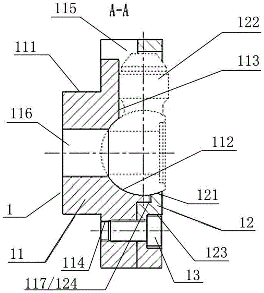
Fig. 5 is a cross-sectional view a-a of fig. 4 in accordance with the present invention.
FIG. 6 is a top view of a second step jig of the present invention.
Fig. 7 is a cross-sectional view B-B of fig. 6 in accordance with the present invention.
In the figure:
1. a first step clamp, 2, a second step clamp, 11, a clamp base, 12, a clamp pressing plate, 13, a fixing bolt,
111. a clamping handle, 112 a positioning spherical surface, 113 a positioning groove, 114 a threaded hole, 115 a chip removal port,
116. chip removal holes 117, positioning steps 121, positioning spherical surfaces 122, machining avoidance areas 123, bolt holes,
124. the positioning step is arranged on the base plate,
21. a clamp base, 22, a clamp pressing plate, 23, a fixing bolt, 211, a clamping handle,
212. a positioning stepped shaft platform, 213 a positioning groove, 214 a threaded hole, 215 a chip removal port, 216 a positioning step,
221. positioning spherical surface, 222, machining an avoiding area, 223, bolt holes and 224, and positioning steps.
Detailed Description
The invention will be further described with reference to the accompanying figures 4-7 and specific examples to assist in understanding the context of the invention.
The invention provides a clamp combination which is used for clamping and fixing a workpiece (a semi-finished product of a rotary pipe joint) when two parallel end surfaces and step holes at two end surfaces of a spherical part of the rotary pipe joint are machined, and comprises a first step clamp 1 and a second step clamp 2. Through the first step fixture 1 and the second step fixture 2, the processes of milling a plane, turning a step inner hole and boring an inner cavity are combined and processed by a numerically controlled lathe, so that the clamping error caused by the conversion of clamping references is reduced, and the machining time and the types of machine tools can be shortened by replacing a milling machine with the numerically controlled lathe for milling the plane.
As shown in fig. 4 and 5, the first process step jig 1 includes a jig base 11, a jig pressing plate 12, and fixing bolts 13 for fitting the jig pressing plate 12 to the jig base 11. The clamp base 11 is provided with a clamping handle 111 and is used for being matched and clamped with a chuck on the numerically controlled lathe. And the positioning spherical surface 112 and the positioning groove 113 are respectively matched and positioned with the spherical surface of the spherical part of the workpiece and the threaded end of the workpiece, and the clamping precision and stability of the semi-finished workpiece are ensured by jointly positioning the spherical part and the threaded end of the workpiece. The clamp base 11 is further provided with symmetrically arranged threaded holes 114 for mounting the fixing bolts 13, and simultaneously, the center position of the positioning spherical surface 112 and the end part of the positioning groove 113 are both provided with a chip removal port 116 and a chip removal hole 115, the diameter of the chip removal hole 116 is slightly larger than the diameter of the inner cavity of the workpiece, so that the chip removal function and the cutter relieving function are achieved, and the inner cavity can be conveniently machined. The fixture base 11 is symmetrically provided with positioning steps 117 at both sides to cooperate with the corresponding positioning steps 124 on the fixture pressing plate 12 to realize accurate positioning of the fixture pressing plate 12 on the fixture base 11.
The inner side wall of the clamp pressing plate 12 is provided with a positioning spherical surface 121 so as to press the workpiece sphere from the outer side of the axial lead of the workpiece sphere, and the positioning spherical surface 112 on the clamp base 11 respectively clamps the workpiece from two sides of the axial lead of the workpiece sphere, so that the clamping and positioning of the workpiece are realized. The clamp pressing plate 12 is provided with a machining avoiding area 122 corresponding to a part to be machined of the workpiece so as to facilitate the machining of an end face, a step hole and an inner cavity by the lower cutter, and the bolt hole 123 and the positioning step 124 are used for installing and positioning the clamp pressing plate on the clamp base.
The sphere center of the positioning spherical surface 112 is overlapped with the axis of the clamping handle 111, the side surface of the positioning groove 113 is in clearance fit with the outer diameter of the pipe joint thread of the processing part, the bottom surface of the positioning groove 113 is in contact positioning with the outer diameter of the pipe joint thread of the processing part, and the pipe joint is limited to rotate by taking the sphere center of the positioning spherical surface 112 as the center.
The positioning spherical surface 112 is matched with the spherical surface of the rotary pipe joint of the processing part.
The outer end of the positioning groove 113 of the clamp base 11 is provided with a chip removal port 115 to avoid the accumulation of the debris from affecting the positioning accuracy.
The clearance holes 116 can prevent the positioning spherical surface 112 from accumulating debris, thereby avoiding the accumulation of debris from affecting the positioning accuracy.
The clamp base 11 and the clamp pressing plate 12 of the first step clamp 1 are positioned by the positioning steps 117 and 124, and the clamp pressing plate 12 is fixed by using two fixing bolts 13 which pass through the bolt holes 123 and are screwed into the threaded holes 114.
As shown in fig. 6 and 7, the second process step jig 2 includes a jig base 21, a jig pressing plate 22, and fixing bolts 23. Like the first step clamp, the clamp base 21 has a clamping handle 211, a positioning groove 213, a threaded hole 214, a clearance hole 215, a positioning step 216 and the like; the clamp pressing plate 22 has a positioning spherical surface 221, a machining avoiding area 222, a bolt hole 223, a positioning step 224 and the like. Unlike the first tool holder, the positioning spherical surface is eliminated and instead the stepped pillow 212 is positioned to accurately position the workpiece in cooperation with the end surface and the stepped hole formed on the upper side of the semi-finished sphere of the workpiece as shown in fig. 7, and the positioning structure functions to ensure the parallelism of the two planes and the coaxiality of the holes.
One end of the positioning groove 213 of the clamp base 21 is provided with a chip removal port 215 to prevent the accumulation of the debris from affecting the positioning accuracy.
The symmetrical center of the positioning step 216 of the fixture base of the second step fixture 2 coincides with the axis of the clamping handle, the end surface of the positioning step axis platform 212 is in contact positioning with the first step processing surface of the rotary pipe joint, the side circumferential surface of the positioning step axis platform 212 is in clearance fit with the inner surface of the first step processing step hole of the rotary pipe joint so as to facilitate clamping operation, and the clearance is smaller than the form and position tolerance of the rotary pipe joint.
The base 21 of the second step clamp 2 and the clamp press plate 22 are positioned by positioning steps 216 and 224.
The diameter of the clamping handle 111 of the first step clamp 1 is the same as that of the clamping handle 211 of the second step clamp 2, so that different step clamps can be conveniently replaced, and the time for replacing the clamps is saved.
The overall shape of the first step clamp and the second step clamp is a revolving body, so that the clamp has better dynamic balance after clamping a workpiece.
The first step clamp 1 and the second step clamp 2 of the invention are adopted to realize the accurate clamping and positioning of the rotary pipe joint, so the processing of two end faces of the ball part, the step hole and the inner cavity can be carried out on the same numerical control lathe. The processing method comprises the following steps:
firstly, a raw material bar is processed into a thread, a conical surface, a sphere and a threaded end inner hole through a numerical control lathe as shown in figure 1, and then the subsequent processing is carried out by using the clamp combination clamp of the invention.
When the clamp combination provided by the invention is used for processing, firstly, a clamping handle 111 of a first step clamp 1 is clamped on a numerical control lathe through a spring pneumatic chuck with a spindle aperture of phi 30mm or phi 20mm, after a clamp base 11 of the first step clamp 1 is fixed on the pneumatic chuck of the numerical control lathe, a semi-finished product of the rotary pipe joint with a processed threaded end and a processed spherical surface of a spherical end is arranged in the clamp base 11, the spherical end of the rotary pipe joint is arranged in a positioning spherical surface 112, the threaded end of the rotary pipe joint is arranged in a positioning groove 113, then a clamp pressure plate 12 is positioned according to positioning steps 117 and 124, the positioning spherical surface 121 is matched with the spherical surface of the rotary pipe joint, and then two fixing bolts 13 are screwed in, so that the part clamping of the first step is completed.
The end face of the spherical end of the rotary pipe joint, the step hole on the side and the inner cavity are machined by the tool of the numerically controlled lathe at the machining avoidance area 122.
The clamping step of the second step clamp is the same as the first step, firstly, after the clamp base 21 of the second step clamp 2 is fixed on a pneumatic chuck of a numerical control lathe through the clamping handle 211, the semi-finished product of the rotary pipe joint with the step hole at the ball end processed in the first step is overturned and loaded into the clamp base 21, the step hole processed in the first step is matched with the positioning step shaft platform 212 of the second step clamp, the threaded end of the rotary pipe joint is placed into the positioning groove 213, then the clamp pressing plate 22 is positioned according to the positioning steps 216 and 224, the positioning spherical surface 221 of the clamp pressing plate 22 is matched with the spherical surface of the rotary pipe joint, and then two fixing bolts 23 are screwed in, so that the part clamping in the second step is completed.
The cutter of the numerically controlled lathe finishes cutting the end face and the stepped hole by machining the avoiding region 222.
The switching of two steps can be realized by replacing the second step clamp on the same numerical control lathe, or clamping the first step clamp on one numerical control lathe, clamping the second step clamp on the other numerical control lathe, and realizing the processing of two steps by switching the stations.
By the clamp combination provided by the invention, the processes of milling the plane, turning the inner hole of the step and machining the inner cavity are combined and processed by adopting the numerical control lathe, so that the clamping error caused by the conversion of the clamping reference is reduced, and meanwhile, the machining time is shortened by replacing the milling machine with the numerical control lathe for milling the plane.
In order to save the clamping time, two working steps are respectively matched with two sets of clamps for changing the clamps, the coaxiality of the inner holes machined at the two ends can reach within 0.05mm through practical verification, and the parallelism of the two end faces is within 0.025 mm. The invention solves the limitation of similar product processing equipment, has faster tool changing time than three-jaw hydraulic chuck counting, and saves the processing cost of the milling machine in the original process. Has good economical efficiency.
The above description is only an example of the present invention and should not be taken as limiting the scope of the invention, and all simple equivalent changes and modifications made within the scope of the present invention and the description thereof are intended to be covered by the present invention.