Disclosure of Invention
The invention provides a multifunctional painting device special for wind collection, which is used for overcoming the defects in the prior art.
The invention is realized by the following technical scheme:
a multifunctional special drawing device for wind mining comprises a supporting platform, wherein a cylindrical groove is formed in the top of the supporting platform, a cylindrical block is arranged in the cylindrical groove, the outer side wall of the cylindrical block is in contact fit with the inner side wall of the cylindrical groove, the bottom of the supporting platform is hinged and connected with a plurality of supporting legs, vertical first through holes are formed in the cylindrical block and the middle of the supporting platform, a same vertical screw rod penetrates through the two first through holes, the lower end of the screw rod is fixedly connected with a hand twisting head, the bottom of the hand twisting head is fixedly connected with a drilling rod, a first annular groove is formed in the middle of the screw rod, an arc plate with a right concave surface is arranged in a left groove of the first annular groove, threads are formed on the concave surface of the arc plate and can be in thread fit connection with the screw rod, the top surface and the bottom surface of the arc plate are in contact fit with the corresponding upper side surface and the lower side, the left side wall of the cylindrical block is provided with a transverse second through hole communicated with the first groove, a stop block is arranged in the first groove corresponding to the arc plate, the same arc plate moving device is arranged in the second through hole and the first groove and connected with the arc plate, the arc plate moving device can control the arc plate to move left and right, the outer side of the upper part of the screw rod is connected with a connecting block with a threaded hole in the middle in a matching way, a plurality of first telescopic rods with upward movable rods are fixedly arranged at the top of the cylindrical block, the upper ends of the movable rods of the first telescopic rods are fixedly connected with the bottom of the connecting block, the side wall of the connecting block is provided with a transverse first threaded through hole, the first threaded through hole is connected with a first screwing bolt in a threaded matching way, the outer side wall of the upper part of the screw rod is vertically and uniformly provided with a plurality of second annular grooves corresponding, but be connected with same drawing board support fixing device through the rotation connection structure that can the locking between the montant of two L type poles, rotate the steerable drawing board of connection structure and support fixing device and can whether rotatory around its articulated shaft.
According to the multifunctional painting equipment special for wind collection, the arc-shaped plate moving device comprises a second hand-operated bolt, a thread is formed in the second through hole, the second hand-operated bolt is connected with the second hand-operated bolt in a matched mode, a right bearing of the second hand-operated bolt is connected with a first connecting rod, the other end of the first connecting rod is fixedly connected with the convex surface of the arc-shaped plate, a transverse first sliding groove is formed in the bottom of the first groove, and a first sliding block is connected with the first sliding groove in a matched mode.
As above, the arc-shaped plate moving device comprises a second connecting rod, the second connecting rod is arranged in the second through hole, one end of the second connecting rod penetrates through the second through hole and then is located on the outer side of the cylindrical block, the other end of the second connecting rod is fixedly connected with the convex surface of the arc-shaped plate, a transverse second sliding groove is formed in the bottom of the first groove, a second sliding block is connected in the second sliding groove in a matched mode, and the second sliding block is fixedly connected with one side of the second sliding groove through a first spring.
As above-mentioned special drawing equipment of multi-functional daylighting, drawing board strutting arrangement include backup pad and back board, but be connected with same back board through the rotation connection structure that can the locking between the montant of two L type poles, the preceding lateral wall of back board is close to lower extreme department fixedly connected with backup pad.
The multifunctional painting equipment special for wind collection comprises two transverse shafts, the tops of the L-shaped rods are fixedly connected with the transverse shafts, the middle parts of the left and right side walls of the drawing board supporting and fixing device are respectively provided with a blind hole corresponding to the transverse shafts, the blind holes are connected with the transverse shafts through bearings, one transverse shaft is provided with a third through hole along the left and right directions, the inner wall of the third through hole is provided with a plurality of transverse third sliding grooves, a third sliding block is connected in the third sliding grooves in a matched manner, the third sliding blocks are fixedly connected with one side of the corresponding third sliding grooves through second springs, the inner ends of all the third sliding blocks are fixedly connected with a same third connecting rod, one end of the third connecting rod passes through the third through hole and then is positioned on the outer side of the transverse shaft, the other end of the third connecting rod is fixedly connected with a gear-shaped inserting rod, the bottom of each blind hole is, the gear-shaped inserted bar can be matched with the slot in an inserting way.
According to the multifunctional painting equipment special for wind collection, one side of the hand twisting head is fixedly connected with the cross rod, and the top surface of the hand twisting head is in contact fit with the bottom surface of the supporting platform.
According to the multifunctional drawing equipment special for wind collection, the inner wall of the cylindrical groove is fixedly connected with the rubber pad.
According to the multifunctional painting equipment special for wind collection, the inner wall of the first through hole is in contact fit with the screw rod.
As to the multifunctional painting equipment special for wind collection, the supporting legs are telescopic rods with lockable lengths.
According to the multifunctional painting equipment special for wind collection, the connecting block is fixedly connected with the L-shaped rod in a detachable fixed connection mode.
The invention has the advantages that: when the support platform is used, the support platform is stably placed through a plurality of support legs, the arc-shaped plate is positioned in the first annular groove, the top surface and the bottom surface of the arc-shaped plate are respectively attached to the upper side surface and the lower side surface of the first annular groove, so that the arc-shaped plate has a movement limiting effect on the screw rod in the vertical direction, the screw rod can only rotate in situ, the first screwing bolt does not enter the second annular groove, the user rotates the screwing head, the connecting block drives the movable rod of the first telescopic rod and the drawing board supporting and fixing device to move upwards until the drawing board supporting and fixing device is at a height suitable for a creator to draw, the arc-shaped plate is controlled to be far away from the first annular groove through the arc-shaped plate moving device until the arc-shaped plate is blocked by the block, the thread arranged on the concave surface of the arc-shaped plate is matched and connected with the thread on the outer side, when a user needs to rotate the drawing board supporting device to rotationally adjust the orientation of the drawing board in the subsequent creation process, the user rotates the hand screw head, the cylindrical block drives the drawing board supporting device to rotate in the supporting platform to adjust the orientation of the drawing board supporting device, the movement of scenery such as the movement of light is generally slow, the drawing board supporting device only needs to rotate by a small angle, and the soil has larger resistance to the drill rod when the drill rod rotates in the soil, therefore, when a user rotates the hand screw head, the rotating speed is slow, the phenomenon that the once rotating amplitude is too large and needs to be adjusted repeatedly can not occur, great vibration can not be caused to the painting, the movement of pigments on the painting, especially the pigments such as printing ink and the like, can be prevented, and the damage of the painting can be prevented; the device is simple in structure and reasonable in design, the matching connection relation between the arc-shaped plate and the screw rod is changed through the change of the position of the arc-shaped plate, so that different functions are realized, the connection among all parts of the device is tighter, the structure of the device is simplified, the operation of the device is simpler, convenience is brought to a user, the height of the drawing board can be adjusted through one function, the labor intensity of the user can be reduced while the device can be well fixed on most outdoor grounds through the other function, and the damage of the work can be prevented by controlling the drawing board to rotate slowly and adjusting the orientation of the drawing board through the other function, and meanwhile, vibration is reduced.
Detailed Description
In order to make the objects, technical solutions and advantages of the embodiments of the present invention clearer, the technical solutions in the embodiments of the present invention will be clearly and completely described below with reference to the drawings in the embodiments of the present invention, and it is obvious that the described embodiments are some, but not all, embodiments of the present invention. All other embodiments, which can be derived by a person skilled in the art from the embodiments given herein without making any creative effort, shall fall within the protection scope of the present invention.
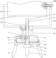
The utility model provides a special drawing equipment of multi-functional wind-gathering, as shown in the figure, including supporting platform 1, cylindrical groove 2 has been seted up at supporting platform 1 top, be provided with cylinder piece 3 in the cylindrical groove 2, the lateral wall of cylinder piece 3 and the inside wall contact cooperation in cylindrical groove 2, supporting platform 1's bottom is articulated to be connected with several supporting legs 4, cylinder piece 3 all sets up vertical first through-hole 5 with supporting platform 1's middle part, pass same vertical screw rod 6 in two first through-holes 5, the lower extreme fixed connection hand of screw rod 6 twists head 7, the bottom fixed connection drilling rod 8 of hand twists head 7, first ring channel 9 is seted up at the middle part of screw rod 6, be provided with the arc 10 that the concave surface faces right in the left side inslot of first ring channel 9, the concave surface of arc 10 is seted up the screw thread and the screw thread that its was seted up can be connected with screw rod 6 screw thread fit, the top surface of arc 10, the lower side surfaces are in contact fit, a first groove 11 is formed in the left side wall of a first through hole 5 in a cylindrical block 3 corresponding to an arc plate 10, a transverse second through hole 12 is formed in the left side wall of the cylindrical block 3 and communicated with the first groove 11, a stop block 13 is arranged in the first groove 11 corresponding to the arc plate 10, the same arc plate moving device is arranged in the second through hole 12 and the first groove 11 and connected with the arc plate 10, the arc plate moving device can control the arc plate 10 to move left and right, the outer side of the upper part of a screw rod 6 is in fit connection with a connecting block 14 with a threaded hole in the middle, a plurality of first telescopic rods 15 with upward movable rods are fixedly arranged at the top of the cylindrical block 3, the upper ends of the movable rods of the first telescopic rods 15 are fixedly connected with the bottom of the connecting block 14, a transverse first threaded through hole 16 is formed in the side wall, the vertical several second annular groove 18 of evenly having seted up of first hand screw bolt 17 of upper portion lateral wall correspondence of screw rod 6, first hand screw bolt 17 can twist in second annular groove 18, both ends symmetric connection has L type pole 19 about connecting block 14, is connected with same drawing board through the rotation connection structure that can the locking between two L type poles 19's the montant and supports fixing device, rotates the steerable drawing board of connection structure and supports fixing device and can whether rotate around its articulated shaft. When the invention is used, the supporting platform 1 is stably placed through the plurality of supporting legs 4, the arc-shaped plate 10 is positioned in the first annular groove 9, the top surface and the bottom surface of the arc-shaped plate 10 are respectively attached to the upper side surface and the lower side surface of the first annular groove 9, so the arc-shaped plate 10 plays a role in limiting the movement of the screw rod 6 in the vertical direction, the screw rod 6 can only rotate in situ, the first hand-screwed bolt 17 does not enter the second annular groove 18, the user rotates the hand-screwed head 7, the connecting block 14 drives the movable rod of the first telescopic rod 15 to move upwards with the drawing board supporting and fixing device until the drawing board supporting and fixing device is at a height suitable for a creator to draw, then the arc-shaped plate moving device controls the arc-shaped plate 10 to be far away from the first annular groove 9 until the arc-shaped plate is blocked by the stop block 13, the thread arranged on the concave surface of the arc, the hand-screw head 7 drives the screw rod 6 and the drill rod 8 to move downwards and insert into the ground, the drill rod 8 moves downwards while rotating, the drill rod 8 can more easily drill into the ground so as to fix the drawing board, after the drill rod 8 drills into a certain depth, the first hand-screw bolt 17 is aligned with one second annular groove, then the first hand-screw bolt 17 is screwed into the second annular groove 18 so as to fix the connecting block 14 and the screw rod 6, at the moment, the cylindrical block 3 is connected with the screw rod 6 into a whole through the first telescopic rod 15 and the connecting block 14, when a user needs to rotate the drawing board supporting device to rotationally adjust the orientation of the drawing board in the subsequent creation process, the user rotates the hand-screw head 7, the cylindrical block 3 drives the drawing board supporting device to rotate in the supporting platform 1 so as to adjust the orientation of the drawing board supporting device, and the movement of scenery such as the movement of light, the drawing board supporting device only needs to rotate by a small angle, and when the drill rod 8 rotates in the soil, the soil has larger resistance to the drill rod 8, so that the rotation speed of a user when the user rotates the hand screwing head 7 is slower, the phenomenon that the once rotation amplitude is too large and needs to be adjusted repeatedly can not occur, larger vibration can not be caused to the drawing, the movement of pigments on the drawing, particularly the pigments such as printing ink and the like can be prevented, and the damage of the drawing can be prevented; the novel drawing board fixing device is simple in structure and reasonable in design, the matching connection relation between the arc-shaped plate 10 and the screw 6 is changed through the change of the position of the arc-shaped plate, and different functions are achieved, so that the connection among all parts of the novel drawing board fixing device is tighter, the structure of the novel drawing board fixing device is simplified, the device is simpler to operate, convenience is brought to users, the height of the drawing board can be adjusted through one function, the labor intensity of the users can be reduced while the novel drawing board fixing device can be well fixed on most outdoor grounds through the other function, and the vibration is reduced while the drawing board is controlled to rotate slowly to adjust the orientation of the drawing board to prevent the damage of works through the third function.
Specifically, as shown in the figures, the arc plate moving device according to the embodiment includes a second hand-operated bolt 21, a thread is formed in the second through hole 12, and the second hand-operated bolt 21 is connected to the second through hole in a matching manner, a right bearing of the second hand-operated bolt 21 is connected to a first connecting rod 22, the other end of the first connecting rod 22 is fixedly connected to the convex surface of the arc plate 10, a transverse first sliding groove 23 is formed in the bottom of the first groove 11, and a first sliding block 24 is connected to the first sliding groove 23 in a matching manner. When the user need move the arc 10 to the direction of keeping away from screw rod 6, the user can be through twisting the second hand bolt 21 control arc 10 of twisting and keeping away from or be close to screw rod 6, through threaded connection cooperation removal arc 10 for do not need external force can realize fixedly through auto-lock nature behind the arc 10 shift position, prevent unstable circumstances such as the arc 10 appears rocking.
Specifically, as shown in the figure, the arc plate moving device according to this embodiment includes a second connecting rod 25, the second connecting rod 25 is disposed in the second through hole 12, one end of the second connecting rod 25 passes through the second through hole 12 and then is located on the outer side of the cylindrical block 3, the other end of the second connecting rod 25 is fixedly connected to the convex surface of the arc plate 10, the bottom of the first groove 11 is provided with a second sliding groove 26, the second sliding groove 26 is internally connected with a second sliding block 27 in a matching manner, and the second sliding block 27 is fixedly connected to one side of the second sliding groove 26 through a first spring 28. The user can control the arc 10 and keep away from screw rod 6 through pulling second connecting rod 25 to the outside, removes the restriction of arc 10 to screw rod 6, and first spring 28 is stretched, loosens second pull rod back first spring 28 and drives arc 10 and reset, and screw rod 6 realization screw-thread fit can be hugged closely to arc 10 under the effect of first spring 28, and the user of being convenient for uses it.
Further, as shown in the drawings, the drawing board supporting device of the present embodiment includes a supporting plate 37 and a back board 38, the two vertical rods of the L-shaped rods 19 are connected with the same back board 38 through a lockable rotating connection structure, and the supporting plate 37 is fixedly connected to a front side wall of the back board 38 near a lower end. The support plate 37 is used to support the bottom of the drawing board, and the back plate 38 provides support for the rear wall of the drawing board, and the two work together to realize good fixation of the drawing board.
Furthermore, as shown in the figure, the rotary connection structure of the embodiment includes two transverse shafts 20, the top of each L-shaped rod 19 is fixedly connected with the transverse shaft 20, the middle portions of the left and right side walls of the drawing board supporting and fixing device are respectively provided with a blind hole 35 corresponding to the transverse shaft 20, the blind holes 35 are connected with the transverse shafts 20 through bearings, one transverse shaft 20 is provided with a third through hole 29 along the left and right direction, the inner wall of the third through hole 29 is provided with a plurality of transverse third sliding grooves 30, the third sliding grooves 30 are respectively and cooperatively connected with a third sliding block 31, the third sliding blocks 31 are respectively and fixedly connected with one side of the corresponding third sliding grooves 30 through second springs 32, the inner ends of all the third sliding blocks 31 are fixedly connected with a same third connecting rod 33, one end of the third connecting rod 33 passes through the third through hole 29 and is located at the outer side of the transverse shaft 20, the other end of the third connecting rod 33 is fixedly connected with a gear-shaped, the gear-like rod 34 is adapted to engage with the slot 36. When the inclination angle of the drawing board supporting device needs to be adjusted, the third connecting rod 33 and the gear-shaped inserting rod 34 are pulled out towards the outer side of the transverse shaft 20, the second spring 32 is stretched, the gear-shaped inserting rod 34 is pulled out of the slot 36, the gear-shaped inserting rod 34 releases the fixation of the drawing board supporting device, at the moment, the drawing board supporting device can rotate around the transverse shaft 20, after the user adjusts the inclination angle of the drawing board supporting device, the user releases the third connecting rod 33, the second spring 32 drives the gear-shaped inserting rod 34 to reset, the user adjusts the inclination angle of the drawing board supporting device through slight rotation, until the slot 36 is aligned with the gear-shaped inserting rod 34, the gear-shaped inserting rod 34 is inserted into the slot 36 again, and the drawing board supporting device is placed to shake.
Furthermore, as shown in the drawings, a cross bar 39 is fixedly connected to one side of the screwing head 7 in the embodiment, and the top surface of the screwing head 7 is in contact fit with the bottom surface of the supporting platform 1. The user rotates hand through horizontal pole 39 and twists head 7 easier, plays laborsaving effect, and the top surface of hand is twisted head 7 and is played the marking effect with the bottom surface contact of supporting platform 1, and the user of being convenient for puts into first ring channel with arc 10 again.
Furthermore, as shown in the drawings, the inner walls of the cylindrical grooves 2 are fixedly connected with rubber pads 40. The rubber pad 40 increases the friction between the cylindrical groove 2 and the cylindrical block 3, and prevents the user from rotating relative to the cylindrical block 3 under the influence of external force when the user does not need to rotate the cylindrical block.
Further, as shown in the figure, the inner wall of the first through hole 5 in the present embodiment is in contact fit with the screw 6. The inner wall of the first through hole 5 is contacted and matched with the screw 6 to play a role in guiding the screw 6.
Furthermore, as shown in the figure, the supporting legs 4 of the present embodiment are telescopic rods with lockable lengths. Supporting leg 4 is the telescopic link that length can be locked and can be applicable to different topography and use, and application scope is wider.
Furthermore, as shown in the drawings, the fixed connection between the connecting block 14 and the L-shaped rod 19 in the embodiment is a detachable fixed connection. The fixed connection between the connecting block 14 and the L-shaped rod 19 is a detachable fixed connection mode, so that the L-shaped rod 19 and the drawing board supporting and fixing device can be detached after a user draws, the size is reduced, and the carrying, the transportation and the storage are convenient.
Finally, it should be noted that: the above examples are only intended to illustrate the technical solution of the present invention, but not to limit it; although the present invention has been described in detail with reference to the foregoing embodiments, it will be understood by those of ordinary skill in the art that: the technical solutions described in the foregoing embodiments may still be modified, or some technical features may be equivalently replaced; and such modifications or substitutions do not depart from the spirit and scope of the corresponding technical solutions of the embodiments of the present invention.