Disclosure of Invention
The invention aims to provide a welding and fixing clamp for manufacturing mechanical equipment, which aims to solve the problems that equipment to be welded needs to be fixed through a clamping block above the clamp in the using process of the welding and fixing clamp for manufacturing mechanical equipment in the background technology, the fixing process is not convenient enough, and the normal use of the welding and fixing clamp is influenced due to the fact that friction damage can be caused on the outer surface of the equipment after the welding and fixing clamp is fixed.
In order to achieve the purpose, the invention provides the following technical scheme: the welding fixing clamp for manufacturing the mechanical equipment comprises an operating platform, wherein a limiting block is movably connected to the front surface of the operating platform, a knob is fixedly connected to one side of the limiting block, a transmission shaft is fixedly connected to the other side of the limiting block, a gear is fixedly connected to the outer surface of the transmission shaft, a second rack is meshed and connected to the upper surface of the gear, a second moving block is fixedly connected to the upper surface of the second rack, a first rack is meshed and connected to the lower surface of the gear, and a first moving block is fixedly connected to the upper surface of the first rack.
Preferably, the inner surfaces of the first moving block and the second moving block are fixedly connected with compression springs, one ends of the compression springs are fixedly connected with connecting rods, and one ends of the connecting rods are fixedly connected with pressing blocks.
Preferably, the outer fixed surface of operation panel is connected with the handle, the lower fixed surface of operation panel is connected with the connecting block, the lower fixed surface of connecting block is connected with rotatory piece, the equal swing joint in both sides of rotatory piece surface has the ball, the surface swing joint of rotatory piece has the support base.
Preferably, the ball is located the internal surface of support base, and with support base swing joint, the surface of rotatory piece is seted up the spout with ball assorted.
Preferably, the ball and the connecting block are movably connected through a rotating block, and the handle and the connecting block are fixedly connected through an operating platform.
Preferably, a rubber pad is arranged on one side of the outer surface of the pressing block, the pressing block is fixedly connected with the compression spring through a connecting rod, and one end of the connecting rod and the compression spring are both located inside the second moving block.
Preferably, the knob and the transmission shaft are fixedly connected through a limiting block, and the gear and the limiting block are fixedly connected through the transmission shaft.
Compared with the prior art, the invention has the beneficial effects that:
1. through the first moving block, the second moving block, the first rack, the second rack and the gear, the problem that the normal use of the device is influenced because the welding fixing clamp for manufacturing mechanical equipment needs to fix the equipment needing to be welded through the clamping block above the clamp in the using process is solved, the fixing process is not convenient enough, and the friction damage to the outer surface of the equipment possibly occurs after the fixing is avoided.
2. Through handle, connecting block, support base, rotatory piece and ball of design, solved mechanical equipment and made with welded fastening anchor clamps when using, finish the equipment centre gripping and weld the processing to it, in order to avoid because device itself can not rotate, be not convenient for according to operating personnel's welding operation adjusting device's the corresponding position orientation, reduce the problem of device availability factor.
Detailed Description
The technical solutions in the embodiments of the present invention will be clearly and completely described below with reference to the drawings in the embodiments of the present invention, and it is obvious that the described embodiments are only a part of the embodiments of the present invention, and not all of the embodiments. All other embodiments, which can be derived by a person skilled in the art from the embodiments given herein without making any creative effort, shall fall within the protection scope of the present invention.
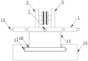
Referring to fig. 1-4, the present invention provides the following technical solutions: the utility model provides a welding mounting fixture is used in mechanical equipment manufacturing, including operation panel 1, the front surface swing joint of operation panel 1 has stopper 8, one side fixedly connected with knob 7 of stopper 8, the opposite side fixedly connected with transmission shaft 12 of stopper 8, the external fixed surface of transmission shaft 12 is connected with gear 11, the last fixed surface meshing of gear 11 is connected with second rack 10, the last fixed surface of second rack 10 is connected with second movable block 3, the lower surface meshing of gear 11 is connected with first rack 9, the first movable block 2 of the last fixed surface of first rack 9.
In this embodiment, in the use process of the device, firstly the knob 7 is rotated to drive the limiting block 8 to rotate, then the limiting block 8 drives the transmission shaft 12 to rotate together with the gear 11 located on the outer surface of the transmission shaft, and the gear 11 drives the second moving block 3 and the first moving block 2 to move relatively through the second rack 10 on the upper surface and the first rack 9 on the lower surface of the gear in the rotating process, so that the device to be welded is clamped or released, and the device to be welded is clamped and fixed conveniently.
Specifically, the inner surfaces of the first moving block 2 and the second moving block 3 are fixedly connected with compression springs 4, one ends of the compression springs 4 are fixedly connected with connecting rods 6, and one ends of the connecting rods 6 are fixedly connected with pressing blocks 5.
In this embodiment, in the process of driving the first moving block 2 and the second moving block 3 to clamp the device, the rubber pad on one side of the pressing block 5 is firstly contacted with the device, then the pressing block 5 is extruded to drive the connecting rod 6 to compress the compression spring 4 towards the inside of the second moving block 3 to force the compression spring, the pressing block 5 is kept in contact with the outer surface of the device under the action of the force of the compression spring 4, the device is kept stably clamped, and the outer surface of the device is prevented from being damaged due to friction.
Specifically, the outer fixed surface of operation panel 1 is connected with handle 13, and the lower fixed surface of operation panel 1 is connected with connecting block 14, and the lower fixed surface of connecting block 14 is connected with rotatory piece 16, and the equal swing joint in both sides of 16 surfaces of rotatory pieces has ball 17, and the surface swing joint of rotatory piece 16 has support base 15.
In this embodiment, can rotate handle 13 and drive the operation panel 1 rotatory among the welding process, then operation panel 1 drives the connecting block 14 rotation of its lower surface, and connecting block 14 drives rotatory piece 16 and is rotatory at the internal surface that supports base 15 to under the effect of ball 17 and 16 outer surface chutes of rotatory piece, reduce the rotatory frictional resistance that receives at the internal surface rotation of support base 15 of rotatory piece 16, be convenient for to the use of device.
Specifically, the ball 17 is located on the inner surface of the supporting base 15 and movably connected with the supporting base 15, and the outer surface of the rotating block 16 is provided with a sliding groove matched with the ball 17.
In this embodiment, the balls 17 located on the inner surface of the supporting base 15 are used to reduce the frictional resistance applied to the rotating block 16 when the inner surface of the supporting base 15 rotates, so as to facilitate the rotation of the rotating block 16.
Specifically, the ball 17 is movably connected with the connecting block 14 through the rotating block 16, and the handle 13 is fixedly connected with the connecting block 14 through the operating platform 1.
In this embodiment, the handle 13 is held, the connecting block 14 and the rotating block 16 are driven to rotate by rotating the handle 13, and the rotating block 16 rotates on the inner surface of the supporting base 15 through the balls 17, so as to control the rotation of the operating table 1.
Specifically, one side of the outer surface of the pressing block 5 is provided with a rubber pad, the pressing block 5 and the compression spring 4 are fixedly connected through a connecting rod 6, and one end of the connecting rod 6 and the compression spring 4 are both located inside the second moving block 3.
In this embodiment, the rubber pad on one side of the outer surface of the pressing block 5 is used for reducing friction damage to the equipment in the fixing process, and the pressing block 5 is kept in contact with the outer surface of the equipment through the rubber pad on one side of the pressing block under the action of the force of the compression spring 4, so that the fixing stability is kept.
Specifically, the knob 7 and the transmission shaft 12 are fixedly connected through the limiting block 8, and the gear 11 and the limiting block 8 are fixedly connected through the transmission shaft 12.
In this embodiment, the rotation knob 7 drives the transmission shaft 12 to rotate through the limiting block 8, and the transmission shaft 12 drives the first rack 9 and the second rack 10 to rotate through the gear 11 on the outer surface of the transmission shaft, so that the welded equipment can be clamped and fixed conveniently.
Although embodiments of the present invention have been shown and described, it will be appreciated by those skilled in the art that changes, modifications, substitutions and alterations can be made in these embodiments without departing from the principles and spirit of the invention, the scope of which is defined in the appended claims and their equivalents.