CN112355773A - A corner grinding device for metal door and window production - Google Patents
A corner grinding device for metal door and window production Download PDFInfo
- Publication number
- CN112355773A CN112355773A CN202011284424.7A CN202011284424A CN112355773A CN 112355773 A CN112355773 A CN 112355773A CN 202011284424 A CN202011284424 A CN 202011284424A CN 112355773 A CN112355773 A CN 112355773A
- Authority
- CN
- China
- Prior art keywords
- plate
- groove
- polishing
- lead screw
- support frame
- Prior art date
- Legal status (The legal status is an assumption and is not a legal conclusion. Google has not performed a legal analysis and makes no representation as to the accuracy of the status listed.)
- Pending
Links
Images


Classifications
-
- B—PERFORMING OPERATIONS; TRANSPORTING
- B24—GRINDING; POLISHING
- B24B—MACHINES, DEVICES, OR PROCESSES FOR GRINDING OR POLISHING; DRESSING OR CONDITIONING OF ABRADING SURFACES; FEEDING OF GRINDING, POLISHING, OR LAPPING AGENTS
- B24B9/00—Machines or devices designed for grinding edges or bevels on work or for removing burrs; Accessories therefor
- B24B9/02—Machines or devices designed for grinding edges or bevels on work or for removing burrs; Accessories therefor characterised by a special design with respect to properties of materials specific to articles to be ground
- B24B9/04—Machines or devices designed for grinding edges or bevels on work or for removing burrs; Accessories therefor characterised by a special design with respect to properties of materials specific to articles to be ground of metal, e.g. skate blades
-
- B—PERFORMING OPERATIONS; TRANSPORTING
- B03—SEPARATION OF SOLID MATERIALS USING LIQUIDS OR USING PNEUMATIC TABLES OR JIGS; MAGNETIC OR ELECTROSTATIC SEPARATION OF SOLID MATERIALS FROM SOLID MATERIALS OR FLUIDS; SEPARATION BY HIGH-VOLTAGE ELECTRIC FIELDS
- B03C—MAGNETIC OR ELECTROSTATIC SEPARATION OF SOLID MATERIALS FROM SOLID MATERIALS OR FLUIDS; SEPARATION BY HIGH-VOLTAGE ELECTRIC FIELDS
- B03C1/00—Magnetic separation
- B03C1/02—Magnetic separation acting directly on the substance being separated
- B03C1/30—Combinations with other devices, not otherwise provided for
-
- B—PERFORMING OPERATIONS; TRANSPORTING
- B24—GRINDING; POLISHING
- B24B—MACHINES, DEVICES, OR PROCESSES FOR GRINDING OR POLISHING; DRESSING OR CONDITIONING OF ABRADING SURFACES; FEEDING OF GRINDING, POLISHING, OR LAPPING AGENTS
- B24B27/00—Other grinding machines or devices
- B24B27/0007—Movable machines
-
- B—PERFORMING OPERATIONS; TRANSPORTING
- B24—GRINDING; POLISHING
- B24B—MACHINES, DEVICES, OR PROCESSES FOR GRINDING OR POLISHING; DRESSING OR CONDITIONING OF ABRADING SURFACES; FEEDING OF GRINDING, POLISHING, OR LAPPING AGENTS
- B24B27/00—Other grinding machines or devices
- B24B27/02—Bench grinders
-
- B—PERFORMING OPERATIONS; TRANSPORTING
- B24—GRINDING; POLISHING
- B24B—MACHINES, DEVICES, OR PROCESSES FOR GRINDING OR POLISHING; DRESSING OR CONDITIONING OF ABRADING SURFACES; FEEDING OF GRINDING, POLISHING, OR LAPPING AGENTS
- B24B41/00—Component parts such as frames, beds, carriages, headstocks
- B24B41/005—Feeding or manipulating devices specially adapted to grinding machines
-
- B—PERFORMING OPERATIONS; TRANSPORTING
- B24—GRINDING; POLISHING
- B24B—MACHINES, DEVICES, OR PROCESSES FOR GRINDING OR POLISHING; DRESSING OR CONDITIONING OF ABRADING SURFACES; FEEDING OF GRINDING, POLISHING, OR LAPPING AGENTS
- B24B41/00—Component parts such as frames, beds, carriages, headstocks
- B24B41/06—Work supports, e.g. adjustable steadies
-
- B—PERFORMING OPERATIONS; TRANSPORTING
- B24—GRINDING; POLISHING
- B24B—MACHINES, DEVICES, OR PROCESSES FOR GRINDING OR POLISHING; DRESSING OR CONDITIONING OF ABRADING SURFACES; FEEDING OF GRINDING, POLISHING, OR LAPPING AGENTS
- B24B47/00—Drives or gearings; Equipment therefor
- B24B47/02—Drives or gearings; Equipment therefor for performing a reciprocating movement of carriages or work- tables
- B24B47/06—Drives or gearings; Equipment therefor for performing a reciprocating movement of carriages or work- tables by liquid or gas pressure only
-
- B—PERFORMING OPERATIONS; TRANSPORTING
- B24—GRINDING; POLISHING
- B24B—MACHINES, DEVICES, OR PROCESSES FOR GRINDING OR POLISHING; DRESSING OR CONDITIONING OF ABRADING SURFACES; FEEDING OF GRINDING, POLISHING, OR LAPPING AGENTS
- B24B55/00—Safety devices for grinding or polishing machines; Accessories fitted to grinding or polishing machines for keeping tools or parts of the machine in good working condition
- B24B55/06—Dust extraction equipment on grinding or polishing machines
Abstract
The invention discloses a corner polishing device for metal door and window production, which comprises a support frame, a polishing mechanism, a scrap collecting mechanism and a fixing mechanism, wherein the fixing mechanism and the polishing mechanism are arranged at the top of the support frame, the fixing mechanism is positioned at one side of the polishing mechanism, the scrap collecting mechanism is arranged at the bottom of the polishing mechanism, and the fixing mechanism comprises a workbench, a ball, a sucker adsorption plate, a positioning plate, a fixing plate, a cylinder and a clamping plate. The clamping plate can be driven to move through the air cylinder, the clamping plate extrudes materials, the edge of the materials to be polished is close to the positioning plate, the functions of clamping and positioning the materials are realized, the sucker adsorption plate can be electrified to adsorb the materials, the materials can be prevented from vibrating in the process of polishing the materials, and the balls are arranged, so that the materials can be conveniently pushed, the materials can be conveniently rotated, and the angle of the materials can be conveniently adjusted.
Description
Technical Field
The invention relates to the technical field of metal door and window production, in particular to a corner polishing device for metal door and window production.
Background
Along with the progress and the development of society, more and more high-rise residential districts appear, people can install burglary-resisting window when living in the high-rise, and burglary-resisting window means on the basis of the original window of building, the additional one deck has netted door and window of theftproof safeguard function, and common burglary-resisting window kind is divided according to the material: the anti-theft window is divided into a fixed anti-theft window and a movable multifunctional sliding anti-theft window according to the using function, and the existing anti-theft window is formed by cutting and welding various sectional materials.
The cutting face of section bar after the cutting has the burr, need polish the burr, and the mode of polishing now is usually that the staff fixes the material on the workstation, then handheld polishing head polishes, and such mode of production is not good to the material effect of polishing, and it is inconvenient to remove the material.
Disclosure of Invention
The invention aims to solve the problems and provide a corner grinding device for metal door and window production.
The invention realizes the purpose through the following technical scheme:
a corner polishing device for metal door and window production comprises a support frame, a polishing mechanism, a scrap collecting mechanism and a fixing mechanism, wherein the fixing mechanism and the polishing mechanism are arranged at the top of the support frame, the fixing mechanism is positioned at one side of the polishing mechanism, the scrap collecting mechanism is arranged at the bottom of the polishing mechanism, the fixing mechanism comprises a workbench, balls, a sucker adsorption plate, a positioning plate, a fixing plate, a cylinder and a clamping plate, the workbench is connected to the center of the top of the support frame through bolts, one side, close to the polishing mechanism, of the top of the workbench is connected with the sucker adsorption plate through bolts, one side of the sucker adsorption plate is connected with the positioning plate through screws, the top of the workbench is also connected with a plurality of balls in a rolling manner, the balls are distributed in an array manner, the fixing plate is arranged at one side, far away from the polishing mechanism, of, just the fixed plate passes through bolted connection in the support frame top, the fixed plate is kept away from there is the cylinder one side of workstation through bolted connection, the output of cylinder passes the fixed plate, and has through bolted connection splint, splint are located the workstation top sets up like this and can drive splint removal through the cylinder, and splint extrusion material for the edge that the material was treated and is polished is close to the locating plate, has realized the function of pressing from both sides tightly and fix a position the material, can also switch on through the sucking disc adsorption plate, makes the sucking disc adsorption plate adsorb the material, can be at the in-process of polishing the material, prevents that the material from vibrating, and wherein the setting up of ball not only can be convenient promote the material, has still made things convenient for and has rotated the material, and then has made things convenient for the adjustment to.
Preferably, a plurality of lower extension supporting plates are arranged at the bottom of the clamping plate and are positioned between the adjacent balls, so that the clamping plate can clamp thin materials under the condition that the clamping plate is not in contact with the balls.
Preferably, the bottom of the support frame is provided with a groove, a first lead screw is arranged on the inner side of the groove, the lower end of the first lead screw penetrates through the groove and is in threaded connection with the groove, the lower end of the first lead screw extends to the bottom of the support frame and is connected with a universal wheel through a bolt, and the bottom of the groove is also connected with a cushion block through a bolt.
Preferably, the bottom of the support frame is provided with a groove, a first lead screw is arranged on the inner side of the groove, the lower end of the first lead screw penetrates through the groove and is in threaded connection with the groove, the lower end of the first lead screw extends to the bottom of the support frame and is connected with a pad foot through a bolt, and the bottom of the groove is also connected with a universal wheel through a bolt.
Preferably, the polishing mechanism comprises a support, a chute, a transmission screw, a transmission motor, a sliding block, a second screw, a mounting frame, a polishing motor and a polishing disc, the support is connected to the top of the support through a bolt, the chute is arranged at the top of the support, the inner side of the chute is connected with the transmission screw through a bearing, the rear end of the transmission screw extends out of the groove and is connected with the transmission motor through a coupling, the outer side of the transmission screw is connected with the sliding block through a thread, the lower end of the second screw penetrates through the sliding block and is connected with the sliding block through a thread and is connected with the mounting frame through a bolt, the polishing motor is connected above the bottom plate of the mounting frame through a bolt, the output end of the polishing motor penetrates through the bottom plate of the mounting frame and is connected with the polishing disc through a bolt, the second lead screw drives the mounting bracket to lift, and then drives the grinding motor and the grinding disc to lift, and whole this device is applicable to polishing of different thickness materials.
Preferably, the bottom plate slope of mounting bracket sets up, and inclination is 45 degrees, sets up like this and not only can realize the function of the burr of polishing, can also carry out the chamfer to the material, reduces the sharpness at material edge, prevents that the material edge from causing the fish tail to personnel.
Preferably, the top of the mounting frame is further connected with a guide rod through a bolt, the upper end of the guide rod penetrates through the sliding block and is in sliding connection with the sliding block, so that the stability of the mounting frame is improved, the stability of the polishing disc is improved, and the polishing effect is benefited.
Preferably, the guide rod is provided with scales, the zero scales of the scales are located above the guide rod, the numerical value displayed by the scales is the same as the vertical distance from the polishing disc to the top of the suction disc adsorption plate, and the height of the polishing disc can be conveniently adjusted.
Preferably, the scrap collecting mechanism comprises a collecting cover, an electromagnet, a flow guide box, a discharge pipe, a supporting plate and a collecting barrel, a mounting groove is further formed in the supporting frame, the electromagnet is connected to the inner side of the mounting groove through a screw, the collecting cover is connected to the top of the electromagnet through a screw, the flow guide box is obliquely arranged on the bottom of the electromagnet through a screw, the discharge pipe communicated with the flow guide box is welded to the rear end of the flow guide box, the supporting plate is connected to the top of the discharge pipe through a screw, a clamping groove is formed in the top of the supporting plate, the collecting barrel is clamped to the inner side of the clamping groove, a collecting frame of the collecting barrel is located below the discharge pipe, and the scrap collecting mechanism can adsorb scrap through the electromagnet and collect scrap through the collecting cover and can enter the collecting barrel through the flow guide box and, the function of automatically cleaning the sweeps is realized.
Preferably, one side of the top of the collecting cover, which is far away from the workbench, is connected with a heightening plate through a bolt, so that the function of collecting scraps is increased.
The technical scheme provided by the invention can have the following beneficial effects:
1. the device can drive the clamping plate to move through the air cylinder, and the clamping plate extrudes the material, so that the edge of the material to be polished is close to the positioning plate, and the functions of clamping and positioning the material are realized;
2. the device can be electrified through the sucker adsorption plate, so that the sucker adsorption plate can adsorb materials, and the materials can be prevented from vibrating in the process of polishing the materials;
3. the arrangement of the balls in the device not only can conveniently push materials, but also facilitates the rotation of the materials, thereby facilitating the adjustment of the angle of the materials.
Additional features of the invention and advantages thereof will be set forth in the description which follows, and in part will be obvious from the description, or may be learned by practice of the invention.
Drawings
The accompanying drawings, which are included to provide a further understanding of the invention and are incorporated in and constitute a part of this specification, illustrate embodiments of the invention and together with the description serve to explain the principles of the invention and not to limit the invention. In the drawings:
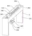
fig. 1 is a schematic structural view of a corner polishing device for metal door and window production according to the present invention;
fig. 2 is a schematic structural view of a first embodiment of a supporting frame of the corner grinding device for metal door and window production according to the present invention;
FIG. 3 is a schematic structural diagram of a fixing mechanism of the corner polishing device for metal door and window production according to the present invention;
fig. 4 is a schematic structural view of a clamping plate of the corner polishing device for metal door and window production according to the present invention;
FIG. 5 is a schematic structural diagram of a polishing mechanism of the corner polishing device for metal door and window production according to the present invention;
FIG. 6 is a sectional view of a grinding mechanism of the corner grinding device for metal door and window production according to the present invention;
FIG. 7 is a schematic structural diagram of a scrap collecting mechanism of the corner polishing device for metal door and window production according to the present invention;
FIG. 8 is a sectional view of a scrap collecting mechanism of the corner polishing device for metal door and window production according to the present invention;
fig. 9 is a schematic structural view of a second embodiment of the support frame of the corner grinding device for metal door and window production according to the present invention.
The reference numerals are explained below:
1. a support frame; 2. a fixing mechanism; 3. a polishing mechanism; 4. a scrap collecting mechanism; 101. a groove; 102. cushion blocks; 103. a first lead screw; 104. a universal wheel; 105. mounting grooves; 11. a foot pad; 201. a work table; 202. a ball bearing; 203. a suction plate of a suction cup; 204. positioning a plate; 205. a fixing plate; 206. a cylinder; 207. a splint; 2071. a lower extension support plate; 301. a support; 302. a chute; 303. a drive screw; 304. a drive motor; 305. a slider; 306. a second lead screw; 307. a mounting frame; 308. polishing the motor; 309. grinding disc; 310. a guide bar; 401. a collection hood; 402. an electromagnet; 403. a flow guide box; 404. a discharge pipe; 405. a support plate; 406. a collection barrel; 407. and (7) a heightening plate.
Detailed Description
The technical solutions in the embodiments of the present invention will be clearly and completely described below with reference to the drawings in the embodiments of the present invention, and it is obvious that the described embodiments are only a part of the embodiments of the present invention, and not all of the embodiments.
In the description of the present invention, it is to be understood that the terms "upper", "lower", "front", "rear", "left", "right", "top", "bottom", "inner", "outer", and the like, indicate orientations or positional relationships based on the orientations or positional relationships shown in the drawings, are merely for convenience in describing the present invention and simplifying the description, and do not indicate or imply that the device or element being referred to must have a particular orientation, be constructed and operated in a particular orientation, and thus, should not be construed as limiting the present invention.
Example 1
As shown in fig. 1-8, a corner polishing device for metal door and window production comprises a support frame 1, a polishing mechanism 3, a scrap collecting mechanism 4, and a fixing mechanism 2, wherein the top of the support frame 1 is provided with the fixing mechanism 2 and the polishing mechanism 3, the fixing mechanism 2 is positioned on one side of the polishing mechanism 3, the bottom of the polishing mechanism 3 is provided with the scrap collecting mechanism 4, the fixing mechanism 2 comprises a workbench 201, balls 202, a suction cup adsorption plate 203, a positioning plate 204, a fixing plate 205, a cylinder 206, and a clamping plate 207, the workbench 201 is connected to the center of the top of the support frame 1 through a bolt, one side of the top of the workbench 201 close to the polishing mechanism 3 is connected with the suction cup adsorption plate 203 through a bolt, one side of the suction cup adsorption plate 203 is connected with the positioning plate 204 through a bolt, the top of the workbench 201 is further connected with a plurality of balls 202 in a rolling manner, the fixing plate 205 is connected to the top of the supporting frame 1 through a bolt, one side of the fixing plate 205, which is far away from the workbench 201, is connected with an air cylinder 206 through a bolt, the output end of the air cylinder 206 penetrates through the fixing plate 205 and is connected with a clamping plate 207 through a bolt, the clamping plate 207 is positioned at the top of the workbench 201, the clamping plate 207 can be driven to move through the air cylinder 206 in the arrangement, the clamping plate 207 extrudes materials, the edge to be polished of the materials is close to the positioning plate 204, the functions of clamping and positioning the materials are realized, the suction disc suction plate 203 can be electrified, the suction disc suction plate 203 can absorb the materials, the materials can be prevented from vibrating in the process of polishing the materials, the ball 202 is arranged to not only conveniently push the materials, but also conveniently rotate the materials, further, the adjustment of the angle of the materials is convenient, a plurality of lower extension support plates 2071 are, the arrangement can ensure that a thin material is clamped under the condition that the clamping plate 207 is not in contact with the ball 202, the bottom of the support frame 1 is provided with the groove 101, the inner side of the groove 101 is provided with the first lead screw 103, the lower end of the first lead screw 103 penetrates through the groove 101 and is in threaded connection with the groove 101 and extends to the bottom of the support frame 1, and is connected with the universal wheel 104 through a bolt, the bottom of the groove 101 is also connected with the cushion block 102 through a bolt, the function of conveniently moving the whole device is realized, and the stability of the whole device is ensured during working, the grinding mechanism 3 comprises a support 301, a chute 302, a transmission lead screw 303, a transmission motor 304, a slide block 305, a second lead screw 306, an installation frame 307, a grinding motor 308 and a grinding disc 309, the support 301 is connected to the top of the support frame 1 through a bolt, the chute 302, the rear end of the transmission screw 303 extends out of the groove 101 and is connected with a transmission motor 304 through a coupler, the outer side of the transmission screw 303 is in threaded connection with a sliding block 305, the lower end of a second screw 306 penetrates through the sliding block 305 and is in threaded connection with the sliding block 305 and is connected with an installation frame 307 through a bolt, a polishing motor 308 is connected above the bottom plate of the installation frame 307 through a bolt, the output end of the polishing motor 308 penetrates through the bottom plate of the installation frame 307 and is connected with a polishing disc 309 through a bolt, the second screw 306 can be rotated to drive the installation frame 307 to ascend and descend, and further drive the polishing motor 308 and the polishing disc 309 to ascend and descend, the whole device is suitable for polishing materials with different thicknesses, the bottom plate of the installation frame 307 is obliquely arranged, the inclination angle is 45 degrees, the function of polishing burrs can be realized through the arrangement, prevent that the material edge from causing the fish tail to personnel, there is the guide bar 310 at the mounting bracket 307 top still through bolted connection, the slider 305 is passed to guide bar 310 upper end, and with slider 305 sliding connection, thus set up and increased the stability of mounting bracket 307, and then increased the stability of polishing disc 309, be favorable to the effect of polishing, be provided with the scale on the guide bar 310, the zero scale of this scale is located the guide bar 310 top, and the numerical value that the scale shows is the same with the vertical distance of polishing disc 309 to sucking disc adsorption plate 203 top, the height that can convenient regulation polishing disc 309 of setting up like this, sweeps collection mechanism 4 includes collection cover 401, electro-magnet 402, baffle box 403, discharging pipe 404, supporting plate 405, collecting vessel 406, still seted up mounting groove 105 on the support frame 1, there is electro-magnet 402 mounting groove 105 inboard through screwed connection, there is collection cover 401 through screwed connection at the electro, the baffle box 403 that the bottom surface slope set up in electromagnet 402 bottom has through the screw connection, the welding of baffle box 403 rear end has the discharging pipe 404 with baffle box 403 intercommunication, there is backup pad 405 at discharging pipe 404 top through the screw connection, backup pad 405 top is provided with the draw-in groove, the inboard joint of this draw-in groove has collecting vessel 406, and collecting vessel 406's collection frame is located discharging pipe 404 below, it can be through the absorption of electromagnet 402 to iron fillings and through collecting cover 401 to the collection of sweeps like this, and enter into inside collecting vessel 406 through baffle box 403 and discharging pipe 404, the function of automatic clearance sweeps has been realized, there is the increase board 407 through bolted connection in one side that workstation 201 was kept away from at collecting cover 401 top, the function of collecting the sweeps has been increased to set up like this.
In the structure, before use, the device is firstly pushed to a proper position, then the first lead screw 103 is rotated, so that the first lead screw 103 drives the universal wheel 104 to ascend until the universal wheel 104 is separated from the ground, at the moment, the cushion block 102 is contacted with the ground, then the height of the polishing disc 309 is adjusted according to the thickness of the material, the second lead screw 306 can be rotated to drive the mounting rack 307 to ascend and descend, the mounting rack 307 drives the polishing motor 308 and the polishing disc 309 to ascend and descend, and in the process, the scales on the guide rod 310 are observed until the numerical value displayed on the guide rod 310 is proper, when the device is used, firstly, the material is placed on the ball 202, then the material is rotated, so that the edge to be polished of the material is close to the polishing mechanism 3, then the air cylinder 206 is started, the air cylinder 206 drives the clamping plate 207 to move, the clamping plate 207 extrudes the material, so that the edge to, make sucking disc adsorption plate 203 adsorb the material, the fixed of material has been realized, then start drive motor 304 and grinding motor 308, to the material of iron, still start electromagnet 402 simultaneously, grinding motor 308's start-up drives grinding disc 309 and rotates, drive motor 304 drives drive lead screw 303 and rotates, drive lead screw 303 has taken slider 305 and has removed, slider 305 drives second lead screw 306 and guide bar 310 and removes, finally drive grinding disc 309 and remove, realize the function of polishing, in this moment, collect cover 401 and increase board 407 and collect the sweeps that the grinding produced, electromagnet 402 adsorbs the iron sweeps, last sweeps enters into collection bucket 406 through baffle box 403 and discharging pipe 404 inside.
Example 2
As shown in fig. 9, embodiment 2 differs from embodiment 1 in that: recess 101 has been seted up to 1 bottom of support frame, and recess 101 inboard is provided with first lead screw 103, and recess 101 is passed to first lead screw 103 lower extreme, and with recess 101 threaded connection to extend to 1 bottom of support frame, and have pad foot 11 through bolted connection, and recess 101 bottom still has universal wheel 104 through bolted connection, sets up the function that has realized conveniently removing whole device like this, and guarantees at the during operation, the stability of whole device.
In the structure, before use, the device is firstly pushed to a proper position, then the first lead screw 103 is rotated, so that the first lead screw 103 drives the pad 11 to descend until the universal wheel 104 is separated from the ground, the pad 11 contacts the ground, then the height of the polishing disc 309 is adjusted according to the thickness of the material, the second lead screw 306 can be rotated to drive the mounting rack 307 to ascend and descend, the mounting rack 307 drives the polishing motor 308 and the polishing disc 309 to ascend and descend, and the scales on the guide rod 310 are observed in the process until the numerical value displayed on the guide rod 310 is proper, when the device is used, the material is firstly placed on the ball 202, then the material is rotated, so that the edge to be polished of the material is close to the polishing mechanism 3, then the air cylinder 206 is started, the air cylinder 206 drives the clamping plate 207 to move, the clamping plate 207 extrudes the material, so that the edge to be polished of the material is close to the positioning, make sucking disc adsorption plate 203 adsorb the material, the fixed of material has been realized, then start drive motor 304 and grinding motor 308, to the material of iron, still start electromagnet 402 simultaneously, grinding motor 308's start-up drives grinding disc 309 and rotates, drive motor 304 drives drive lead screw 303 and rotates, drive lead screw 303 has taken slider 305 and has removed, slider 305 drives second lead screw 306 and guide bar 310 and removes, finally drive grinding disc 309 and remove, realize the function of polishing, in this moment, collect cover 401 and increase board 407 and collect the sweeps that the grinding produced, electromagnet 402 adsorbs the iron sweeps, last sweeps enters into collection bucket 406 through baffle box 403 and discharging pipe 404 inside.
The foregoing illustrates and describes the principles, general features, and advantages of the present invention. It will be understood by those skilled in the art that the present invention is not limited to the embodiments described above, which are described in the specification and illustrated only to illustrate the principle of the present invention, but that various changes and modifications may be made therein without departing from the spirit and scope of the present invention, which fall within the scope of the invention as claimed. The scope of the invention is defined by the appended claims and equivalents thereof.
Claims (10)
1. The utility model provides a corner grinding device for metal door and window production, includes support frame (1), grinding machanism (3), sweeps collection mechanism (4), its characterized in that: the scrap collecting and polishing device is characterized by further comprising a fixing mechanism (2), the fixing mechanism (2) and the polishing mechanism (3) are arranged at the top of the support frame (1), the fixing mechanism (2) is located on one side of the polishing mechanism (3), the scrap collecting mechanism (4) is arranged at the bottom of the polishing mechanism (3), the fixing mechanism (2) comprises a workbench (201), balls (202), a sucker adsorption plate (203), a positioning plate (204), a fixing plate (205), an air cylinder (206) and a clamping plate (207), the workbench (201) is connected to the center of the top of the support frame (1) through bolts, the sucker adsorption plate (203) is connected to one side, close to the polishing mechanism (3), of the top of the workbench (201) through bolts, the positioning plate (204) is connected to one side of the sucker adsorption plate (203) through bolts, the plurality of balls (202) are further connected to the top of the workbench (201, just ball (202) array distribution, workstation (201) are kept away from one side of grinding machanism (3) is provided with fixed plate (205), just fixed plate (205) pass through bolted connection in support frame (1) top, fixed plate (205) are kept away from there is cylinder (206) one side of workstation (201) through bolted connection, the output of cylinder (206) passes fixed plate (205), and has through bolted connection splint (207), splint (207) are located workstation (201) top.
2. A corner grinding device for metal door and window production according to claim 1, characterized in that: the bottom of the clamping plate (207) is provided with a plurality of lower extension supporting plates (2071), and the lower extension supporting plates (2071) are positioned between the intervals of the adjacent balls (202).
3. A corner grinding device for metal door and window production according to claim 1, characterized in that: the bottom of the support frame (1) is provided with a groove (101), a first lead screw (103) is arranged on the inner side of the groove (101), the lower end of the first lead screw (103) penetrates through the groove (101), is in threaded connection with the groove (101), extends to the bottom of the support frame (1), is connected with a universal wheel (104) through a bolt, and is further connected with a cushion block (102) through a bolt at the bottom of the groove (101).
4. A corner grinding device for metal door and window production according to claim 1, characterized in that: the bottom of the support frame (1) is provided with a groove (101), a first lead screw (103) is arranged on the inner side of the groove (101), the lower end of the first lead screw (103) penetrates through the groove (101), is in threaded connection with the groove (101), extends to the bottom of the support frame (1), is connected with a pad foot (11) through a bolt, and is further connected with a universal wheel (104) through a bolt at the bottom of the groove (101).
5. A corner grinding device for metal door and window production according to claim 1, characterized in that: the polishing mechanism (3) comprises a support (301), a sliding groove (302), a transmission lead screw (303), a transmission motor (304), a sliding block (305), a second lead screw (306), an installation frame (307), a polishing motor (308) and a polishing disc (309), wherein the support (301) is connected to the top of the support frame (1) through bolts, the sliding groove (302) is formed in the top of the support (301), the transmission lead screw (303) is connected to the inner side of the sliding groove (302) through a bearing, the rear end of the transmission lead screw (303) extends out of the groove (101) and is connected with the transmission motor (304) through a coupling, the sliding block (305) is connected to the outer side of the transmission lead screw (303) through threads, the lower end of the second lead screw (306) penetrates through the sliding block (305) and is connected with the sliding block (305) through threads and, the grinding motor (308) is connected above the bottom plate of the mounting frame (307) through bolts, the output end of the grinding motor (308) penetrates through the bottom plate of the mounting frame (307), and the grinding disc (309) is connected through bolts.
6. A corner grinding device for metal door and window production according to claim 5, characterized in that: the bottom plate of the mounting frame (307) is arranged in an inclined mode, and the inclined angle is 45 degrees.
7. A corner grinding device for metal door and window production according to claim 5, characterized in that: the top of the mounting frame (307) is further connected with a guide rod (310) through a bolt, and the upper end of the guide rod (310) penetrates through the sliding block (305) and is in sliding connection with the sliding block (305).
8. A corner grinding device for metal door and window production according to claim 7, characterized in that: the guide rod (310) is provided with scales, the zero scale of the scales is located above the guide rod (310), and the numerical value displayed by the scales is the same as the vertical distance from the polishing disc (309) to the top of the sucker adsorption plate (203).
9. A corner grinding device for metal door and window production according to claim 1, characterized in that: the scrap collecting mechanism (4) comprises a collecting cover (401), an electromagnet (402), a flow guide box (403), a discharge pipe (404), a supporting plate (405) and a collecting barrel (406), the support frame (1) is also provided with an installation groove (105), the inner side of the installation groove (105) is connected with the electromagnet (402) through a screw, the top of the electromagnet (402) is connected with the collecting cover (401) through a screw, the bottom of the electromagnet (402) is connected with the flow guide box (403) with the inner bottom surface obliquely arranged through a screw, the rear end of the flow guide box (403) is welded with the discharge pipe (404) communicated with the flow guide box (403), the top of the discharge pipe (404) is connected with the supporting plate (405) through a screw, the top of the supporting plate (405) is provided with a clamping groove, the collecting barrel (406) is clamped on the inner side of the clamping groove, and the collecting frame of the collecting barrel (406) is positioned below the discharge pipe (404).
10. A corner grinding device for metal door and window production according to claim 9, characterized in that: one side of the top of the collecting cover (401), which is far away from the workbench (201), is connected with a heightening plate (407) through a bolt.
Priority Applications (1)
| Application Number | Priority Date | Filing Date | Title |
|---|---|---|---|
| CN202011284424.7A CN112355773A (en) | 2020-11-17 | 2020-11-17 | A corner grinding device for metal door and window production |
Applications Claiming Priority (1)
| Application Number | Priority Date | Filing Date | Title |
|---|---|---|---|
| CN202011284424.7A CN112355773A (en) | 2020-11-17 | 2020-11-17 | A corner grinding device for metal door and window production |
Publications (1)
| Publication Number | Publication Date |
|---|---|
| CN112355773A true CN112355773A (en) | 2021-02-12 |
Family
ID=74515788
Family Applications (1)
| Application Number | Title | Priority Date | Filing Date |
|---|---|---|---|
| CN202011284424.7A Pending CN112355773A (en) | 2020-11-17 | 2020-11-17 | A corner grinding device for metal door and window production |
Country Status (1)
| Country | Link |
|---|---|
| CN (1) | CN112355773A (en) |
Cited By (1)
| Publication number | Priority date | Publication date | Assignee | Title |
|---|---|---|---|---|
| CN114043335A (en) * | 2021-11-12 | 2022-02-15 | 哈尔滨职业技术学院 | Robot part cleaning and deburring device |
Citations (9)
| Publication number | Priority date | Publication date | Assignee | Title |
|---|---|---|---|---|
| KR20130086747A (en) * | 2012-01-26 | 2013-08-05 | 주식회사 케이엔제이 | Work edge grinding apparatus |
| CN205166644U (en) * | 2015-11-30 | 2016-04-20 | 桐乡市凯瑞包装材料有限公司 | Adjustable steel sheet burnishing device |
| CN107891330A (en) * | 2017-06-08 | 2018-04-10 | 成都中创空间科技有限公司 | A kind of automatically sheet metal grinding apparatus |
| CN207858520U (en) * | 2017-12-25 | 2018-09-14 | 成都壹橙科技有限公司 | A kind of unmanned machine part grinding apparatus |
| CN208304643U (en) * | 2018-05-14 | 2019-01-01 | 东莞市银泰丰光学科技有限公司 | A kind of glass light guide plate bevel edge processing unit (plant) |
| CN210550064U (en) * | 2019-08-01 | 2020-05-19 | 绍兴三雄汽配有限公司 | Auto-parts grinding device |
| CN211051962U (en) * | 2020-06-16 | 2020-07-21 | 山东华农生物制药有限公司 | Veterinary medicine soluble powder split charging amount detection device |
| CN211441726U (en) * | 2019-12-31 | 2020-09-08 | 广西圣堡朗科技有限公司 | Scientific and technological information propaganda equipment |
| CN211490819U (en) * | 2019-10-14 | 2020-09-15 | 天津瑞麦格科技有限公司 | Follow-on automatic edging machine |
-
2020
- 2020-11-17 CN CN202011284424.7A patent/CN112355773A/en active Pending
Patent Citations (9)
| Publication number | Priority date | Publication date | Assignee | Title |
|---|---|---|---|---|
| KR20130086747A (en) * | 2012-01-26 | 2013-08-05 | 주식회사 케이엔제이 | Work edge grinding apparatus |
| CN205166644U (en) * | 2015-11-30 | 2016-04-20 | 桐乡市凯瑞包装材料有限公司 | Adjustable steel sheet burnishing device |
| CN107891330A (en) * | 2017-06-08 | 2018-04-10 | 成都中创空间科技有限公司 | A kind of automatically sheet metal grinding apparatus |
| CN207858520U (en) * | 2017-12-25 | 2018-09-14 | 成都壹橙科技有限公司 | A kind of unmanned machine part grinding apparatus |
| CN208304643U (en) * | 2018-05-14 | 2019-01-01 | 东莞市银泰丰光学科技有限公司 | A kind of glass light guide plate bevel edge processing unit (plant) |
| CN210550064U (en) * | 2019-08-01 | 2020-05-19 | 绍兴三雄汽配有限公司 | Auto-parts grinding device |
| CN211490819U (en) * | 2019-10-14 | 2020-09-15 | 天津瑞麦格科技有限公司 | Follow-on automatic edging machine |
| CN211441726U (en) * | 2019-12-31 | 2020-09-08 | 广西圣堡朗科技有限公司 | Scientific and technological information propaganda equipment |
| CN211051962U (en) * | 2020-06-16 | 2020-07-21 | 山东华农生物制药有限公司 | Veterinary medicine soluble powder split charging amount detection device |
Cited By (2)
| Publication number | Priority date | Publication date | Assignee | Title |
|---|---|---|---|---|
| CN114043335A (en) * | 2021-11-12 | 2022-02-15 | 哈尔滨职业技术学院 | Robot part cleaning and deburring device |
| CN114043335B (en) * | 2021-11-12 | 2022-09-20 | 哈尔滨职业技术学院 | Robot part cleaning and deburring device |
Similar Documents
| Publication | Publication Date | Title |
|---|---|---|
| CN213054122U (en) | Automobile parts grinding device convenient to angle regulation | |
| CN112355773A (en) | A corner grinding device for metal door and window production | |
| CN214642343U (en) | Edge grinding device for machining disc-shaped workpiece | |
| CN212977720U (en) | Deburring equipment for surface of sprayed part | |
| CN212527136U (en) | Grinding device for metal part machining | |
| CN210173932U (en) | Glass curtain wall cutting device with edging function | |
| CN114734508B (en) | Cutting machine for processing rigid polyurethane foam | |
| CN217018736U (en) | Drilling equipment is used in brake block processing | |
| CN217394522U (en) | A grinding device for mechanical equipment corner burr | |
| CN112192439B (en) | Plastic plate processing device | |
| CN213164790U (en) | Polishing machine for machining stainless steel mechanical parts | |
| CN212653244U (en) | Woodworking polishing machine convenient to use | |
| CN218109679U (en) | Full-automatic engraving and milling machine | |
| CN214817207U (en) | Sanding machine polishing structure for plate processing | |
| CN217513527U (en) | Deburring equipment for grinding wheel spindle machining | |
| CN216177253U (en) | Intelligent grooving machine for aluminum template processing | |
| CN215748441U (en) | Environment-friendly polishing device for high-stability flange plate | |
| CN220762019U (en) | Dustproof casting piece grinding device | |
| CN218746840U (en) | Glass is burnishing and polishing device for handicraft | |
| CN219026900U (en) | Aluminum veneer processing polisher with dust collection function | |
| CN217914506U (en) | Surface leveling device for automobile plastic part | |
| CN214445197U (en) | Sheet metal deburring device convenient to adjust | |
| CN220073475U (en) | Clamping device for gear hobbing machine | |
| CN211193297U (en) | Grinding device for automobile brake shoe | |
| CN210818840U (en) | Lath cleaning device |
Legal Events
| Date | Code | Title | Description |
|---|---|---|---|
| PB01 | Publication | ||
| PB01 | Publication | ||
| SE01 | Entry into force of request for substantive examination | ||
| SE01 | Entry into force of request for substantive examination | ||
| RJ01 | Rejection of invention patent application after publication | ||
| RJ01 | Rejection of invention patent application after publication |
Application publication date: 20210212 |