CN112344424A - High-temperature water heating system - Google Patents
High-temperature water heating system Download PDFInfo
- Publication number
- CN112344424A CN112344424A CN202011080717.3A CN202011080717A CN112344424A CN 112344424 A CN112344424 A CN 112344424A CN 202011080717 A CN202011080717 A CN 202011080717A CN 112344424 A CN112344424 A CN 112344424A
- Authority
- CN
- China
- Prior art keywords
- communicating pipe
- heater
- heating system
- water
- fixed
- Prior art date
- Legal status (The legal status is an assumption and is not a legal conclusion. Google has not performed a legal analysis and makes no representation as to the accuracy of the status listed.)
- Pending
Links
- XLYOFNOQVPJJNP-UHFFFAOYSA-N water Substances O XLYOFNOQVPJJNP-UHFFFAOYSA-N 0.000 title claims abstract description 81
- 238000010438 heat treatment Methods 0.000 title claims abstract description 49
- 239000007788 liquid Substances 0.000 claims abstract description 28
- 238000012544 monitoring process Methods 0.000 claims description 4
- 238000010586 diagram Methods 0.000 description 5
- 238000000034 method Methods 0.000 description 3
- 238000004891 communication Methods 0.000 description 2
- 238000001816 cooling Methods 0.000 description 2
- 239000000463 material Substances 0.000 description 2
- 230000003020 moisturizing effect Effects 0.000 description 2
- 238000004378 air conditioning Methods 0.000 description 1
- 230000009286 beneficial effect Effects 0.000 description 1
- 238000005516 engineering process Methods 0.000 description 1
- 230000017525 heat dissipation Effects 0.000 description 1
- 230000006698 induction Effects 0.000 description 1
- 238000011177 media preparation Methods 0.000 description 1
- 238000012986 modification Methods 0.000 description 1
- 230000004048 modification Effects 0.000 description 1
- 238000009423 ventilation Methods 0.000 description 1
Images




Classifications
-
- F—MECHANICAL ENGINEERING; LIGHTING; HEATING; WEAPONS; BLASTING
- F24—HEATING; RANGES; VENTILATING
- F24D—DOMESTIC- OR SPACE-HEATING SYSTEMS, e.g. CENTRAL HEATING SYSTEMS; DOMESTIC HOT-WATER SUPPLY SYSTEMS; ELEMENTS OR COMPONENTS THEREFOR
- F24D13/00—Electric heating systems
- F24D13/04—Electric heating systems using electric heating of heat-transfer fluid in separate units of the system
-
- F—MECHANICAL ENGINEERING; LIGHTING; HEATING; WEAPONS; BLASTING
- F24—HEATING; RANGES; VENTILATING
- F24D—DOMESTIC- OR SPACE-HEATING SYSTEMS, e.g. CENTRAL HEATING SYSTEMS; DOMESTIC HOT-WATER SUPPLY SYSTEMS; ELEMENTS OR COMPONENTS THEREFOR
- F24D19/00—Details
-
- F—MECHANICAL ENGINEERING; LIGHTING; HEATING; WEAPONS; BLASTING
- F24—HEATING; RANGES; VENTILATING
- F24D—DOMESTIC- OR SPACE-HEATING SYSTEMS, e.g. CENTRAL HEATING SYSTEMS; DOMESTIC HOT-WATER SUPPLY SYSTEMS; ELEMENTS OR COMPONENTS THEREFOR
- F24D19/00—Details
- F24D19/10—Arrangement or mounting of control or safety devices
- F24D19/1096—Arrangement or mounting of control or safety devices for electric heating systems
-
- F—MECHANICAL ENGINEERING; LIGHTING; HEATING; WEAPONS; BLASTING
- F24—HEATING; RANGES; VENTILATING
- F24D—DOMESTIC- OR SPACE-HEATING SYSTEMS, e.g. CENTRAL HEATING SYSTEMS; DOMESTIC HOT-WATER SUPPLY SYSTEMS; ELEMENTS OR COMPONENTS THEREFOR
- F24D2200/00—Heat sources or energy sources
- F24D2200/08—Electric heater
Landscapes
- Engineering & Computer Science (AREA)
- Physics & Mathematics (AREA)
- Thermal Sciences (AREA)
- Chemical & Material Sciences (AREA)
- Combustion & Propulsion (AREA)
- Mechanical Engineering (AREA)
- General Engineering & Computer Science (AREA)
- Heat-Pump Type And Storage Water Heaters (AREA)
Abstract
The invention discloses a high-temperature water heating system, and relates to the technical field of heating equipment. The invention comprises a heat exchanger, a circulating pump and a heater, wherein the heater is connected with a water storage tank through a pipeline, the input end of the heat exchanger is connected with the output end of the circulating pump through a second communicating pipe, the input end of the circulating pump is connected with the output end of the heater through a third communicating pipe, and a first electromagnetic valve is arranged in the middle of the third communicating pipe and used for controlling the circulation of liquid in the third communicating pipe. According to the invention, the circulating pump is started to directly exchange heat with the heating system for the hot water at 90-95 ℃ in the water storage tank, the indoor temperature can be rapidly raised, when the return water is higher than 50 ℃, the system forms a circulation, the return water is lower than 50 ℃, the water storage tank is connected with the device, and through repeated circulation, the heat exchange efficiency of the device is greatly improved, the consumption of the device is greatly reduced, and the energy is effectively saved.
Description
Technical Field
The invention belongs to the technical field of heating equipment, and particularly relates to a high-temperature water heating system.
Background
The heating system is a general name of technology, equipment and service for maintaining the temperature required by life or work indoors by consuming certain energy and supplying heat to the rooms by using a manual method, and the heating system consists of three main parts, namely heating, ventilation and air conditioning, of heat medium preparation (heat source), heat medium conveying and heat medium utilization (heat dissipation equipment).
Disclosure of Invention
The invention aims to provide a high-temperature water heating system, which solves the existing problems: the heat exchange efficiency of the existing device is poor, the efficiency of improving the indoor temperature is poor, and the energy consumed by the device is large.
In order to solve the technical problems, the invention is realized by the following technical scheme:
the invention relates to a high-temperature water heating system which comprises a heat exchanger, a circulating pump and a heater, wherein the heater is connected with a water storage tank through a pipeline, the input end of the heat exchanger is connected with the output end of the circulating pump through a second communicating pipe, the input end of the circulating pump is connected with the output end of the heater through a third communicating pipe, and a first electromagnetic valve is arranged in the middle of the third communicating pipe and used for controlling the circulation of liquid in the third communicating pipe;
the input end of the heater is connected with the output end of the heat exchanger through a first communicating pipe and a fifth communicating pipe, a second electromagnetic valve is installed in the middle of the fifth communicating pipe and used for controlling the liquid inside the fifth communicating pipe to circulate, a temperature control valve is installed between the first communicating pipe and the fifth communicating pipe and used for monitoring the temperature of the circulated liquid, a fourth communicating pipe is installed between the fifth communicating pipe and the third communicating pipe and used for communicating the third communicating pipe with the fifth communicating pipe, and a third electromagnetic valve is installed in the middle of the fourth communicating pipe and used for controlling the liquid inside the fourth communicating pipe to circulate;
and an electric cabinet is fixed at one end of the heater and used for controlling the operation of the device.
The high-temperature water heating system comprises a heat exchange main body, wherein a hot water inlet pipe is fixed at one end of the heat exchange main body and is used for being connected with a second communicating pipe, and a cold water outlet pipe is fixed at the other end of the heat exchange main body and is used for being connected with a first communicating pipe.
Further, the heat exchanger also comprises two support frames, and the support frames are fixed at the lower end of the heat exchange main body.
Further, the heater includes the frame, the inside of frame is fixed with the heating main part, the upper end of heating main part is fixed with the hot water outlet pipe for connect with the third communicating pipe, the lower extreme of heating main part is fixed with the cold water inlet tube, be connected with fifth communicating pipe, the one end of heating main part upper end is fixed with first water supply valve, the other end of heating main part upper end is fixed with second water supply valve, the heater is connected with the water storage tank through first water supply valve and second water supply valve, discharge valve is still installed to the one end of heating main part.
Further, the rated voltage of the electric cabinet is 220V.
Further, the rated sensing temperature of the temperature control valve is 50 ℃.
Further, the liquid in the water storage tank is hot water with the temperature of 90-95 ℃.
Further, the circulating pump is in an intermittent working state, and after working for one hour, the circulating pump is rested for one hour and is circulated repeatedly.
The invention has the following beneficial effects:
according to the invention, the circulating pump is started to directly exchange heat with the heating system for the hot water at 90-95 ℃ in the water storage tank, the indoor temperature can be rapidly raised, when the return water is higher than 50 ℃, the system forms a circulation, the return water is lower than 50 ℃, the water storage tank is connected with the device, and through repeated circulation, the heat exchange efficiency of the device is greatly improved, the consumption of the device is greatly reduced, and the energy is effectively saved.
Of course, it is not necessary for any product in which the invention is practiced to achieve all of the above-described advantages at the same time.
Drawings
In order to more clearly illustrate the technical solutions of the embodiments of the present invention, the drawings used in the description of the embodiments will be briefly introduced below, and it is obvious that the drawings in the following description are only some embodiments of the present invention, and it is obvious for those skilled in the art that other drawings can be obtained according to the drawings without creative efforts.
Fig. 1 is a schematic diagram of the overall structure of a high-temperature water heating system according to the present invention;
FIG. 2 is a schematic structural diagram of one end of a high temperature water heating system according to the present invention;
FIG. 3 is a schematic structural view of the other end of the high temperature water heating system of the present invention;
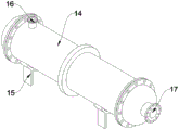
FIG. 4 is a schematic structural diagram of a heat exchanger of a high temperature water heating system according to the present invention;
FIG. 5 is a schematic structural diagram of a heater of a high temperature water heating system according to the present invention;
fig. 6 is a system schematic diagram of a high temperature water heating system of the present invention.
In the drawings, the components represented by the respective reference numerals are listed below:
1. a heat exchanger; 2. a circulation pump; 3. a heater; 4. an electric cabinet; 5. a first solenoid valve; 6. a second solenoid valve; 7. a third electromagnetic valve; 8. a temperature control valve; 9. a first communication pipe; 10. a second communicating pipe; 11. a third communicating pipe; 12. a fourth communicating pipe; 13. a fifth communicating pipe; 14. a heat exchange body; 15. a support frame; 16. a hot water inlet pipe; 17. a cold water outlet pipe; 18. a frame; 19. heating the body; 20. a hot water outlet pipe; 21. a first water replenishing valve; 22. a second water replenishing valve; 23. an exhaust valve; 24. a cold water inlet pipe.
Detailed Description
The technical solutions in the embodiments of the present invention will be clearly and completely described below with reference to the drawings in the embodiments of the present invention, and it is obvious that the described embodiments are only a part of the embodiments of the present invention, and not all of the embodiments. All other embodiments, which can be derived by a person skilled in the art from the embodiments given herein without making any creative effort, shall fall within the protection scope of the present invention.
Referring to fig. 1-6, the present invention is a high temperature water heating system, including a heat exchanger 1, a circulating pump 2 and a heater 3, wherein an input end of the heat exchanger 1 is connected to an output end of the circulating pump 2 through a second communicating pipe 10, an input end of the circulating pump 2 is connected to an output end of the heater 3 through a third communicating pipe 11, a first electromagnetic valve 5 is installed in a middle position of the third communicating pipe 11 to control the circulation of liquid inside the third communicating pipe 11, and the liquid inside the heater 3 is pumped into the heat exchanger 1 after the circulating pump 2 is started;
specifically, the circulating pump 2 is in an intermittent working state, and after working for one hour, the circulating pump is rested for one hour and is circulated repeatedly;
in detail, the heater 3 is connected with a water storage tank through a pipeline, so that the liquid in the water storage tank can circulate with the device, and the liquid in the water storage tank is hot water with the temperature of 90-95 ℃;
the input end of the heater 3 is connected with the output end of the heat exchanger 1 through a first communicating pipe 9 and a fifth communicating pipe 13, a second electromagnetic valve 6 is installed in the middle of the fifth communicating pipe 13 and used for controlling the circulation of liquid in the fifth communicating pipe 13, a temperature control valve 8 is installed between the first communicating pipe 9 and the fifth communicating pipe 13 and used for monitoring the temperature of the circulating liquid, the rated induction temperature of the temperature control valve 8 is 50 ℃, when the temperature control valve 8 senses that the temperature of the liquid circulating in the first communicating pipe 9 is higher than 50 ℃, a first water replenishing valve 21 and a second water replenishing valve 22 can be automatically opened to enable a water storage tank to be added into the circulation of the device, a fourth communicating pipe 12 is installed between the fifth communicating pipe 13 and the third communicating pipe 11 and used for communicating the third communicating pipe 11 and the fifth communicating pipe 13, and a third electromagnetic valve 7 is installed in the middle of the fourth communicating pipe 12, for controlling the circulation of the liquid inside the fourth communication pipe 12;
in detail, the heat exchanger 1 comprises a heat exchange main body 14, a hot water inlet pipe 16 is fixed at one end of the heat exchange main body 14 and is used for being connected with the second communicating pipe 10, a cold water outlet pipe 17 is fixed at the other end of the heat exchange main body 14 and is used for being connected with the first communicating pipe 9, and two support frames 15 are fixed at the lower end of the heat exchange main body 14, so that the heat exchange main body 14 can be more stably fixed;
specifically, the heater 3 includes a frame 18, a heating body 19 is fixed inside the frame 18, a hot water outlet pipe 20 is fixed at the upper end of the heating body 19 and is used for being connected with the third communicating pipe 11, a cold water inlet pipe 24 is fixed at the lower end of the heating body 19 and is used for being connected with the fifth communicating pipe 13, a first water replenishing valve 21 is fixed at one end of the upper end of the heating body 19, a second water replenishing valve 22 is fixed at the other end of the upper end of the heating body 19, the heater 3 is connected with the water storage tank through the first water replenishing valve 21 and the second water replenishing valve 22, and an exhaust valve 23 is further installed at one end of the heating;
further, an electric cabinet 4 is fixed at one end of the heater 3 for controlling the operation of the device, and the rated voltage of the electric cabinet 4 is 220V.
One specific application of this embodiment is: when the device is used, the device is started through an external power supply electrically connected with a device lead, the heater 3 heats liquid after being started, the liquid which is heated after the circulating pump 2 is started is sent into the heat exchanger 1 through the third communicating pipe 11 and the second communicating pipe 10, the liquid is rapidly cooled after being processed by the heat exchanger 1, and a large amount of heat energy is released in the cooling process;
liquid can get into the inside of heater 3 through first communicating pipe 9 and fifth communicating pipe 13 after the cooling, in flow process temperature control valve 8 can advance the monitoring to the temperature of liquid, when liquid temperature is higher than 50 degrees centigrade, can be through the inside of circulating pump 2 suction heat exchanger 1 again after heating of heater 3, when liquid temperature is less than 50 degrees centigrade, first moisturizing valve 21 and second moisturizing valve 22 can open automatically, connect heater 3 and water storage tank, the inside liquid of water storage tank can enter into the inside of heater 3, promote the temperature of the inside liquid of heater 3.
In the description herein, references to the description of "one embodiment," "an example," "a specific example" or the like are intended to mean that a particular feature, structure, material, or characteristic described in connection with the embodiment or example is included in at least one embodiment or example of the invention. In this specification, the schematic representations of the terms used above do not necessarily refer to the same embodiment or example. Furthermore, the particular features, structures, materials, or characteristics described may be combined in any suitable manner in any one or more embodiments or examples.
The preferred embodiments of the invention disclosed above are intended to be illustrative only. The preferred embodiments are not intended to be exhaustive or to limit the invention to the precise embodiments disclosed. Obviously, many modifications and variations are possible in light of the above teaching. The embodiments were chosen and described in order to best explain the principles of the invention and the practical application, to thereby enable others skilled in the art to best utilize the invention. The invention is limited only by the claims and their full scope and equivalents.
Claims (8)
1. A high temperature water heating system which is characterized in that: the device comprises a heat exchanger (1), a circulating pump (2) and a heater (3), wherein the heater (3) is connected with a water storage tank through a pipeline, the input end of the heat exchanger (1) is connected with the output end of the circulating pump (2) through a second communicating pipe (10), the input end of the circulating pump (2) is connected with the output end of the heater (3) through a third communicating pipe (11), and a first electromagnetic valve (5) is installed in the middle of the third communicating pipe (11) and used for controlling the circulation of liquid in the third communicating pipe (11);
the input end of the heater (3) is connected with the output end of the heat exchanger (1) through a first communicating pipe (9) and a fifth communicating pipe (13), a second electromagnetic valve (6) is installed at the middle position of the fifth communicating pipe (13) and used for controlling the circulation of liquid inside the fifth communicating pipe (13), a temperature control valve (8) is installed between the first communicating pipe (9) and the fifth communicating pipe (13) and used for monitoring the temperature of the circulating liquid, a fourth communicating pipe (12) is installed between the fifth communicating pipe (13) and the third communicating pipe (11) and used for communicating the third communicating pipe (11) with the fifth communicating pipe (13), and a third electromagnetic valve (7) is installed at the middle position of the fourth communicating pipe (12) and used for controlling the circulation of liquid inside the fourth communicating pipe (12);
and an electric cabinet (4) is fixed at one end of the heater (3) and used for controlling the operation of the device.
2. A high-temperature water heating system as claimed in claim 1, wherein the heat exchanger (1) comprises a heat exchange main body (14), one end of the heat exchange main body (14) is fixed with a hot water inlet pipe (16) for connecting with the second communicating pipe (10), and the other end of the heat exchange main body (14) is fixed with a cold water outlet pipe (17) for connecting with the first communicating pipe (9).
3. A high-temperature water heating system as claimed in claim 2, wherein the heat exchanger (1) further comprises two support frames (15), and the support frames (15) are fixed at the lower end of the heat exchange body (14).
4. The high-temperature water heating system according to claim 1, wherein the heater (3) comprises a frame (18), a heating main body (19) is fixed inside the frame (18), a hot water outlet pipe (20) is fixed at the upper end of the heating main body (19) and is used for being connected with a third communicating pipe (11), a cold water inlet pipe (24) is fixed at the lower end of the heating main body (19) and is used for being connected with a fifth communicating pipe (13), a first water replenishing valve (21) is fixed at one end of the upper end of the heating main body (19), a second water replenishing valve (22) is fixed at the other end of the upper end of the heating main body (19), the heater (3) is connected with a water storage tank through the first water replenishing valve (21) and the second water replenishing valve (22), and an exhaust valve (23) is further installed at one end of the heating main body (19).
5. A high-temperature water heating system as claimed in claim 1, wherein the rated voltage of the electric cabinet (4) is 220V.
6. A high temperature water heating system according to claim 1, wherein the rated sensing temperature of the temperature control valve (8) is 50 degrees celsius.
7. A high temperature water heating system as claimed in claim 1, wherein the liquid inside the water storage tank is hot water at a temperature of 90-95 degrees celsius.
8. A high temperature water heating system as claimed in claim 1, wherein the circulation pump (2) is in intermittent operation, and after one hour of operation, the circulation pump is in rest for one hour and is in repeated circulation.
Priority Applications (1)
| Application Number | Priority Date | Filing Date | Title |
|---|---|---|---|
| CN202011080717.3A CN112344424A (en) | 2020-10-10 | 2020-10-10 | High-temperature water heating system |
Applications Claiming Priority (1)
| Application Number | Priority Date | Filing Date | Title |
|---|---|---|---|
| CN202011080717.3A CN112344424A (en) | 2020-10-10 | 2020-10-10 | High-temperature water heating system |
Publications (1)
| Publication Number | Publication Date |
|---|---|
| CN112344424A true CN112344424A (en) | 2021-02-09 |
Family
ID=74361695
Family Applications (1)
| Application Number | Title | Priority Date | Filing Date |
|---|---|---|---|
| CN202011080717.3A Pending CN112344424A (en) | 2020-10-10 | 2020-10-10 | High-temperature water heating system |
Country Status (1)
| Country | Link |
|---|---|
| CN (1) | CN112344424A (en) |
Cited By (2)
| Publication number | Priority date | Publication date | Assignee | Title |
|---|---|---|---|---|
| CN112902285A (en) * | 2021-03-16 | 2021-06-04 | 蓝小春 | Water heating and circulating flow device in heating system |
| CN114413324A (en) * | 2022-02-22 | 2022-04-29 | 南京港华能源投资发展有限公司第一分公司 | Data analysis system and method for efficient central heating of cold and heat source machine room |
Citations (7)
| Publication number | Priority date | Publication date | Assignee | Title |
|---|---|---|---|---|
| GB2352805A (en) * | 1999-08-04 | 2001-02-07 | Gledhill Water Storage | Hot water system |
| JP2009299927A (en) * | 2008-06-10 | 2009-12-24 | Mitsubishi Electric Corp | Storage type water heater |
| CN105465879A (en) * | 2014-08-15 | 2016-04-06 | 国家电网公司 | Heating system based on electric heating energy storage device and control method of heating system |
| CN206207528U (en) * | 2016-10-11 | 2017-05-31 | 吉林铁道勘察设计院有限公司 | A.T.C, the heating system of moisturizing |
| CN208671135U (en) * | 2018-07-20 | 2019-03-29 | 中科瑞奥能源科技股份有限公司 | Electrical heating system |
| CN210320247U (en) * | 2019-07-23 | 2020-04-14 | 沈阳瑞科斯节能科技有限公司 | Heating system |
| CN211060228U (en) * | 2019-10-30 | 2020-07-21 | 天津百安科技有限公司 | High-vacuum heat-insulation water circulation heating device |
-
2020
- 2020-10-10 CN CN202011080717.3A patent/CN112344424A/en active Pending
Patent Citations (7)
| Publication number | Priority date | Publication date | Assignee | Title |
|---|---|---|---|---|
| GB2352805A (en) * | 1999-08-04 | 2001-02-07 | Gledhill Water Storage | Hot water system |
| JP2009299927A (en) * | 2008-06-10 | 2009-12-24 | Mitsubishi Electric Corp | Storage type water heater |
| CN105465879A (en) * | 2014-08-15 | 2016-04-06 | 国家电网公司 | Heating system based on electric heating energy storage device and control method of heating system |
| CN206207528U (en) * | 2016-10-11 | 2017-05-31 | 吉林铁道勘察设计院有限公司 | A.T.C, the heating system of moisturizing |
| CN208671135U (en) * | 2018-07-20 | 2019-03-29 | 中科瑞奥能源科技股份有限公司 | Electrical heating system |
| CN210320247U (en) * | 2019-07-23 | 2020-04-14 | 沈阳瑞科斯节能科技有限公司 | Heating system |
| CN211060228U (en) * | 2019-10-30 | 2020-07-21 | 天津百安科技有限公司 | High-vacuum heat-insulation water circulation heating device |
Cited By (2)
| Publication number | Priority date | Publication date | Assignee | Title |
|---|---|---|---|---|
| CN112902285A (en) * | 2021-03-16 | 2021-06-04 | 蓝小春 | Water heating and circulating flow device in heating system |
| CN114413324A (en) * | 2022-02-22 | 2022-04-29 | 南京港华能源投资发展有限公司第一分公司 | Data analysis system and method for efficient central heating of cold and heat source machine room |
Similar Documents
| Publication | Publication Date | Title |
|---|---|---|
| CN103542614B (en) | heating and refrigerating system | |
| CN202494217U (en) | Direct flow circulation type air energy water heater | |
| CN104764314A (en) | Air source heat pump centralized heating distribution method and device for intensive curing barns | |
| CN100513933C (en) | Dual-purpose machine for hot water and air conditioning | |
| CN102353179B (en) | Air-conditioning hot-water system | |
| CN204830506U (en) | Electric heat cycle recycle system of family | |
| CN104089444B (en) | A kind of industrial cold and hot balancing machine group system control method and control device thereof | |
| CN210089036U (en) | Solar auxiliary heating, refrigeration and hot water supply triple heat supply pump system | |
| CN221076721U (en) | Waste heat recycling device | |
| CN209042515U (en) | A kind of electric heating plumbing fixture | |
| CN218884314U (en) | Triple co-generation system | |
| CN118009408A (en) | Indoor constant temperature device for heating of water heater | |
| CN111536638B (en) | Integrated air conditioning system based on air source and solar energy coupling | |
| CN204854070U (en) | Air -source heat pump trigeminy supplies unit | |
| CN223344220U (en) | An air heating system for an air compressor waste heat recovery aging room | |
| CN208595723U (en) | A kind of low-temperature air source heat pump | |
| CN213984044U (en) | Air compressor machine waste heat comprehensive utilization system | |
| CN205718059U (en) | A kind of solar heat pump and water heating, cold air, heating installation all-in-one | |
| CN113623814B (en) | A rapid heating central air-conditioning water cycle control system and control method | |
| CN219367983U (en) | Heat pump hot water system | |
| CN222562705U (en) | Heat energy recovery device of fuel cell test bench | |
| CN104964458A (en) | Household appliance heat circulation recycling system | |
| CN223106203U (en) | Air source heat pump cold air recovery and utilization device | |
| CN105758060B (en) | A kind of solar heat pump and water heating, cold air, heating all-in-one | |
| CN222210843U (en) | System for utilize centrifugal air compressor machine waste heat to realize adjusting temperature |
Legal Events
| Date | Code | Title | Description |
|---|---|---|---|
| PB01 | Publication | ||
| PB01 | Publication | ||
| SE01 | Entry into force of request for substantive examination | ||
| SE01 | Entry into force of request for substantive examination | ||
| RJ01 | Rejection of invention patent application after publication |
Application publication date: 20210209 |
|
| RJ01 | Rejection of invention patent application after publication |