CN112317468A - Efficient cleaning process for large-scale conveying pipeline - Google Patents
Efficient cleaning process for large-scale conveying pipeline Download PDFInfo
- Publication number
- CN112317468A CN112317468A CN202011084725.5A CN202011084725A CN112317468A CN 112317468 A CN112317468 A CN 112317468A CN 202011084725 A CN202011084725 A CN 202011084725A CN 112317468 A CN112317468 A CN 112317468A
- Authority
- CN
- China
- Prior art keywords
- cleaning
- pipeline
- scale
- cleaning process
- conveying
- Prior art date
- Legal status (The legal status is an assumption and is not a legal conclusion. Google has not performed a legal analysis and makes no representation as to the accuracy of the status listed.)
- Withdrawn
Links
- 238000004140 cleaning Methods 0.000 title claims abstract description 142
- 238000000034 method Methods 0.000 title claims abstract description 35
- 230000008569 process Effects 0.000 title claims abstract description 30
- 238000005406 washing Methods 0.000 claims abstract description 29
- 230000007246 mechanism Effects 0.000 claims description 46
- XLYOFNOQVPJJNP-UHFFFAOYSA-N water Substances O XLYOFNOQVPJJNP-UHFFFAOYSA-N 0.000 claims description 36
- 239000000463 material Substances 0.000 claims description 20
- 230000000903 blocking effect Effects 0.000 claims description 10
- 239000007788 liquid Substances 0.000 claims description 10
- 238000004519 manufacturing process Methods 0.000 claims description 8
- 230000000712 assembly Effects 0.000 claims 1
- 238000000429 assembly Methods 0.000 claims 1
- 230000003028 elevating effect Effects 0.000 abstract description 2
- 238000007599 discharging Methods 0.000 abstract 1
- 230000009471 action Effects 0.000 description 4
- 239000003245 coal Substances 0.000 description 4
- 230000000694 effects Effects 0.000 description 4
- 230000033001 locomotion Effects 0.000 description 4
- 230000005540 biological transmission Effects 0.000 description 3
- 238000009434 installation Methods 0.000 description 3
- 238000001125 extrusion Methods 0.000 description 2
- 230000002349 favourable effect Effects 0.000 description 2
- 238000005096 rolling process Methods 0.000 description 2
- 238000005201 scrubbing Methods 0.000 description 2
- 229910000831 Steel Inorganic materials 0.000 description 1
- 230000004075 alteration Effects 0.000 description 1
- 238000004458 analytical method Methods 0.000 description 1
- 230000009286 beneficial effect Effects 0.000 description 1
- 239000003250 coal slurry Substances 0.000 description 1
- 230000007547 defect Effects 0.000 description 1
- 238000005516 engineering process Methods 0.000 description 1
- 238000011010 flushing procedure Methods 0.000 description 1
- 230000005484 gravity Effects 0.000 description 1
- 239000010720 hydraulic oil Substances 0.000 description 1
- 238000011065 in-situ storage Methods 0.000 description 1
- 238000012986 modification Methods 0.000 description 1
- 230000004048 modification Effects 0.000 description 1
- 239000003921 oil Substances 0.000 description 1
- 239000003208 petroleum Substances 0.000 description 1
- 238000003825 pressing Methods 0.000 description 1
- 239000007921 spray Substances 0.000 description 1
- 239000010959 steel Substances 0.000 description 1
- 239000000126 substance Substances 0.000 description 1
- 238000006467 substitution reaction Methods 0.000 description 1
- 239000002699 waste material Substances 0.000 description 1
Images




Classifications
-
- B—PERFORMING OPERATIONS; TRANSPORTING
- B08—CLEANING
- B08B—CLEANING IN GENERAL; PREVENTION OF FOULING IN GENERAL
- B08B9/00—Cleaning hollow articles by methods or apparatus specially adapted thereto
- B08B9/02—Cleaning pipes or tubes or systems of pipes or tubes
- B08B9/027—Cleaning the internal surfaces; Removal of blockages
-
- B—PERFORMING OPERATIONS; TRANSPORTING
- B08—CLEANING
- B08B—CLEANING IN GENERAL; PREVENTION OF FOULING IN GENERAL
- B08B13/00—Accessories or details of general applicability for machines or apparatus for cleaning
-
- B—PERFORMING OPERATIONS; TRANSPORTING
- B08—CLEANING
- B08B—CLEANING IN GENERAL; PREVENTION OF FOULING IN GENERAL
- B08B9/00—Cleaning hollow articles by methods or apparatus specially adapted thereto
- B08B9/02—Cleaning pipes or tubes or systems of pipes or tubes
- B08B9/023—Cleaning the external surfaces
Landscapes
- Engineering & Computer Science (AREA)
- Mechanical Engineering (AREA)
- Cleaning In General (AREA)
Abstract
The invention discloses a high-efficiency cleaning process for a large-scale conveying pipeline, which specifically comprises the following steps: s1, measuring the size, S2, judging whether cleaning can be carried out, S3, feeding, S4, starting cleaning, S5, discharging and circulating the next pipeline for cleaning. This a high-efficient cleaning process for large-scale pipeline, can realize wasing simultaneously inside and outside large-scale pipeline, need not to wash the outside of pipeline in addition, the work burden of cleaning personnel has been alleviateed, fine reaching is concentrated the purpose of going on simultaneously with the inside and outside washing of pipeline together, it is thorough to wash, thereby cleaning personnel's cleaning work has been made things convenient for greatly, can realize large batch automatic washing, can realize adopting simple structure can realize carrying out automatic washing simultaneously to the inside and outside surface of pipeline, need not to formulate great elevating system and use, it is lower to wasing the place requirement.
Description
Technical Field
The invention relates to the technical field of conveying pipeline processing, in particular to an efficient cleaning process for a large-scale conveying pipeline.
Background
The conveying pipeline is a pipeline specially used for conveying liquid and gas materials, is called pipeline transportation by adopting a pipeline conveying material method, is a special transportation mode for conveying petroleum, coal and chemical products to the market from a production place, is a special component part for trunk line transportation in a uniform transportation network, is a pipeline made of materials suitable for different use occasions, is widely applied to a process pipeline of a metallurgical mine, a tailing conveying pipeline, a coal washing and coal dressing plant process pipeline, a coal gangue discharge conveying pipeline and the conveying of remote finished coal slurry, the large-scale conveying pipeline is widely used, a multi-pipeline finished product is required to be cleaned in the production process of the large-scale conveying pipeline, the original cleaning mode is that the pipeline is directly washed through a flushing pipe or is intensively lifted to a cleaning pool through a crane to be soaked and cleaned, and the cleaning method is complicated.
Referring to chinese patent publication No. CN111468483A, a push-type large-scale pipe internal cleaning device is disclosed as reference patent 1, the whole vehicle frame can be driven to move by pushing the push handle, the vehicle frame drives the first magnet to move for a moment through the connecting rod and the mounting frame, the second magnet can drive the cleaning roller to move, the cleaning roller can clean the inside of the pipeline in the moving process, the operation is simple, the cleaning efficiency is high, the moving wheel can rotate along the inner side wall of the large pipeline by the movement of the cleaning mechanism to drive the cleaning roller to move to rotate to clean the pipeline, the cam can drive the installation rod to move left and right through the connecting ball, the installation rod can drive the cleaning roller to move left and right through the connecting block, the cleaning roller can move left and right at intervals when rotating, the same position inside the pipeline can be cleaned for many times, the cleaning is more thorough, and the cleaning effect is better.
Refer to chinese patent publication CN 107537833A's a large-scale pipeline belt cleaning device, mark as reference patent 2, this patent passes through the motor belt and drives the folding rod, and the folding rod is folding to drive the rotation type cleaning brush and is the downstream, and the rotation axis motion of rotation type cleaning brush central part drives the pivot circumferential direction of both sides, and installs first scrubbing portion and the second scrubbing portion in the pivot and can use the pivot to realize the rotation as the rotation center to can realize the cleanness to the pipeline inner wall.
A comprehensive analysis of the above referenced patents can yield the following drawbacks:
1) refer to patent 1 and refer to patent 2 and only can wash the inside of single pipeline, wash still not thoroughly, can not realize wasing large-scale pipeline's inside and outside simultaneously, accomplish the back to the inside washing of pipeline, still need wash the outside of pipeline in addition, increased cleaning personnel's work burden, can't reach the purpose of going on simultaneously together with the inside and outside washing of pipeline is concentrated to the washing work of giving cleaning personnel brings very big inconvenience.
2) Refer to patent 1 and refer to patent 2 and can not realize large batch automatic washing, once wash the completion back to referring to patent 1, need the cleaning personnel to promote whole cleaning equipment to carry out the washing of next pipeline, waste time and energy and the pipe diameter of pipeline is not of uniform size, refer to patent 1's application range and comparatively limit, be unfavorable for using widely, refer to patent 2 and wash a pipeline after, need stand next pipeline, the process of making the pipeline stand itself is just very loaded down with trivial details, especially to the great steel material pipeline of pipe diameter, and is large in size, the quality is heavy, it is very hard to stand the pipeline, consequently, two patents of referring to can not realize automatic washing, can't reach not only fast but also the efficient and carry out abluent mesh to large-scale pipeline.
3) Refer to patent 1's washing structure comparatively complicated, realize wasing the characteristic structure at pipeline inside motion through adopting a large amount of transmission structures, and insert the pipeline with a large amount of transmission structures, high in production cost, very be unfavorable for using widely, and refer to patent 2 and adopt simple washing structure to wash the pipeline, nevertheless have certain use restriction, when the length of highly surpassing the washing structure of pipeline, obviously can not carry out the inside whole washing of pipeline, and refer to patent 2's washing structure and need follow in down inserting the pipeline, when the pipeline height is higher, need be equipped with the great elevating system of high stroke and just can normal use, therefore such cleaning equipment is bulky, it is higher to require the washing place.
Disclosure of Invention
Technical problem to be solved
Aiming at the defects of the prior art, the invention provides an efficient cleaning process for a large-scale conveying pipeline, and solves the problems that the existing large-scale conveying pipeline cleaning equipment can only clean the interior of a single pipeline, the cleaning is still not thorough, the simultaneous cleaning of the inside and the outside of the large-scale conveying pipeline cannot be realized, the large-batch automatic cleaning cannot be realized, the cleaning structure is complex, and the requirement on a cleaning site is high.
(II) technical scheme
In order to achieve the purpose, the invention is realized by the following technical scheme: a high-efficiency cleaning process for a large-scale conveying pipeline specifically comprises the following steps:
s1, measuring the inner pipe diameter, the outer pipe diameter and the length of the pipeline to be cleaned by measuring equipment;
s2, judging whether the inner diameter, the outer diameter and the length of the cleaning device meet the cleaning size requirement of the internal and external integrated cleaning device according to the size data measured in the step S1;
s3, if the pipeline is judged to be qualified in the step S2, the pipeline to be cleaned is horizontally conveyed to a conveying mechanism of the inside and outside integrated cleaning equipment through the feeding equipment;
s4, starting internal and external integrated cleaning equipment to perform internal and external motorized cleaning on the pipeline loaded in the step S3;
s5, after one pipeline in the step S4 is cleaned, unloading, conveying the next pipeline to be cleaned, repeating the cleaning step of the step S4, and cleaning, and repeating the steps until all large conveying pipelines to be cleaned are cleaned.
Wherein, step S2-S4 inside and outside integral type cleaning equipment, include two wiper mechanism and install the conveying mechanism between two wiper mechanism, the wiper mechanism includes can be subaerial quick-witted case and quick-witted roof portion fixed mounting 'S that removes motor case through the universal wheel, there is driving motor inside of motor case through mounting panel fixed mounting, and one side activity of motor case is provided with interior washing subassembly, there is outer washing subassembly at the top of motor case through L shape support mounting, one side fixed mounting that the top of motor case just is located L shape support has hydraulic unit, and the inside fixed mounting of quick-witted case has water supply unit and control assembly, conveying mechanism' S both sides all are provided with shelves material subassembly.
Interior washing subassembly includes to rotate through the bearing and connects in the threaded rod of motor case one side, the one end of threaded rod runs through the motor case and extends to the inside of motor case, and the threaded rod extends to the one end of motor incasement portion and passes through bearing and driving motor's output shaft fixed connection, the surface threaded connection of threaded rod has the screw thread cover body, and the surface fixed mounting of the screw thread cover body has fixed disc, a plurality of hydraulic telescoping rod is installed through the connecting plate dead lever to the surface of fixed disc, and the equal fixed mounting in end that stretches out of a plurality of hydraulic telescoping rod has the washing brush, arbitrary the outside fixed mounting who washs the brush has pressure sensor, the surface of the screw thread cover body just is located the equal fixed mounting in both sides of fixed disc has the water-passing disc, and the surface of water-passing disc has.
Preferably, the outer cleaning assembly comprises a lifting hydraulic cylinder fixedly installed on the L-shaped support through a connecting plate, the extending end of the lifting hydraulic cylinder is fixedly provided with an arc plate through the connecting plate, the bottom of the arc plate is fixedly provided with a shunt pipe, and the bottom of the shunt pipe is fixedly provided with a plurality of upper nozzles.
Preferably, conveying mechanism includes installing frame and fixed mounting in the material loading swash plate in installing frame both sides four corners, there is motor power one side at the installing frame back through A-frame fixed mounting, and the inner wall of installing frame is connected with drive shaft and driven shaft through bearing rotation respectively, the surface cover of drive shaft and driven shaft is equipped with the conveyer belt, and the surface of conveyer belt is connected with a plurality of roller bearing through the mounting bracket rotation.
Preferably, the material blocking component comprises two rotary hydraulic cylinders fixedly mounted on the front side and the rear side of the bottom of the conveying mechanism, the extending ends of the rotary hydraulic cylinders are fixedly connected with swing rods through fixing sleeves, cross rods are fixedly connected between the two swing rods, and the outer surfaces of the cross rods are rotatably connected with rollers through bearings.
Preferably, the liquid passing port of the hydraulic unit is communicated with the liquid passing ports of the hydraulic cylinders in the inner cleaning assembly, the outer cleaning assembly and the material blocking assembly through pipelines respectively.
Preferably, the water through port of the water supply unit is respectively communicated with the water through disc and the water inlet of the outer cleaning assembly through a conduit.
Preferably, the control assembly comprises a central processing unit, a data comparator, a feedback module and a time relay which are fixedly installed in the case respectively, and the signal end of the central processing unit is electrically connected with the signal ends of the data comparator, the feedback module, the time relay and the pressure sensor through wires respectively.
Preferably, a control panel and an indicator light are fixedly mounted on a door of the case respectively.
Preferably, the feeding device in the step S3 is a forklift or a production line blanking mechanism connected to a conveying mechanism of the internal and external integrated cleaning device.
(III) advantageous effects
The invention provides an efficient cleaning process for a large-scale conveying pipeline. Compared with the prior art, the method has the following beneficial effects:
(1) this a high-efficient cleaning technology for large-scale pipeline, its wiper mechanism includes can be subaerial quick-witted case and quick-witted roof portion fixed mounting's motor case that removes through the universal wheel, there is driving motor inside of motor case through mounting panel fixed mounting, and one side activity of motor case is provided with interior washing subassembly, there is outer washing subassembly at the top of motor case through L shape support mounting, can realize wasing large-scale pipeline's inside and outside simultaneously, need not to wash the outside of pipeline in addition, the staff's work burden has been alleviateed, fine reached with the concentrated purpose of going on simultaneously together of the inside and outside washing of pipeline, wash thoroughly, thereby the washing work of staff has made things convenient for greatly.
(2) The high-efficiency cleaning process for the large-scale conveying pipeline comprises a conveying mechanism, a cleaning mechanism and a cleaning mechanism, wherein the conveying mechanism comprises a mounting frame and feeding inclined plates fixedly mounted at four corners of two sides of the mounting frame, one side of the back surface of the mounting frame is fixedly provided with a power motor through a triangular support, the inner wall of the mounting frame is rotatably connected with a driving shaft and a driven shaft through respective bearings, a conveyor belt is sleeved on the outer surfaces of the driving shaft and the driven shaft, the outer surface of the conveyor belt is rotatably connected with a plurality of rolling shafts through a mounting frame, can realize large batch automatic washing, only need lead to and transport the pipeline to conveying mechanism on can carry out automatic inside and outside washing, labour saving and time saving can be applicable to the pipeline washing of different pipe diameters size, application range is wider, is favorable to using widely, need not earlier stage cost increase process and carries, the material loading is simple, fine reached not only quick but also the efficient carries out abluent purpose to large-scale pipeline.
(3) The inner cleaning component comprises a threaded rod which is rotatably connected to one side of the motor box through a bearing, one end of the threaded rod penetrates through the motor box and extends into the motor box, one end of the threaded rod extending into the motor box is fixedly connected with an output shaft of a driving motor through the bearing, the outer surface of the threaded rod is in threaded connection with a threaded sleeve body, and a fixing disc is fixedly arranged on the outer surface of the threaded sleeve body, so that the inner surface and the outer surface of the pipeline can be automatically cleaned simultaneously by adopting a simple structure, a large number of transmission structures are not required to be adopted for cleaning characteristic structures, the production cost is saved, the large-scale cleaning process is very favorable for popularization and use, meanwhile, the large-scale cleaning process can also be used for comprehensively cleaning the long pipeline by arranging a front cleaning mechanism and a rear cleaning mechanism, and a large lifting mechanism is not, the requirement on cleaning sites is low.
Drawings
FIG. 1 is a schematic structural view of the present invention;
FIG. 2 is a side view of the structure of the present invention;
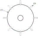
FIG. 3 is a side view of the inner wash assembly of the present invention;
FIG. 4 is a schematic view of the inner cleaning assembly of the present invention;
FIG. 5 is a side view of the interior of the drain pan of the present invention;
FIG. 6 is a side view of the arcuate plate structure of the present invention;
FIG. 7 is a top view of the delivery mechanism of the present invention;
FIG. 8 is a schematic structural view of a material stopping assembly according to the present invention;
fig. 9 is a cross-sectional view of the chassis and motor case structure of the present invention.
In the figure, 1 cleaning mechanism, 11 universal wheels, 12 cases, 13 motor cases, 14 driving motors, 15 internal cleaning components, 151 threaded rods, 152 threaded sleeves, 153 fixed disks, 154 hydraulic telescopic rods, 155 cleaning brushes, 156 pressure sensors, 157 water passing disks, 158 lower nozzles, 16 external cleaning components, 161 lifting hydraulic cylinders, 162 arc plates, 163 shunt tubes, 164 upper nozzles, 17 hydraulic units, 18 water supply units, 19 control components, 191 central processing units, 192 data comparators, 193 feedback modules, 194 time relays, 2 conveying mechanisms, 21 mounting frames, 22 feeding inclined plates, 23 power motors, 24 driving shafts, 25 driven shafts, 26 conveyor belts, 27 rolling shafts, 3 material blocking components, 31 rotary hydraulic cylinders, 32 swing rods, 33 cross rods, 34 rollers, 4 control panels and 5 indicator lamps.
Detailed Description
The technical solutions in the embodiments of the present invention will be clearly and completely described below with reference to the drawings in the embodiments of the present invention, and it is obvious that the described embodiments are only a part of the embodiments of the present invention, and not all of the embodiments. All other embodiments, which can be derived by a person skilled in the art from the embodiments given herein without making any creative effort, shall fall within the protection scope of the present invention.
Referring to fig. 1-9, an embodiment of the present invention provides a technical solution: a high-efficiency cleaning process for a large-scale conveying pipeline specifically comprises the following steps:
s1, measuring the inner pipe diameter, the outer pipe diameter and the length of the pipeline to be cleaned by measuring equipment;
s2, judging whether the inner diameter, the outer diameter and the length of the cleaning device meet the cleaning size requirement of the internal and external integrated cleaning device according to the size data measured in the step S1;
s3, if the pipeline to be cleaned is judged to be qualified in the step S2, the pipeline to be cleaned is horizontally conveyed to a conveying mechanism of the internal and external integrated cleaning equipment through a feeding device, the feeding device in the step S3 is a forklift or a production line blanking mechanism connected with the conveying mechanism of the internal and external integrated cleaning equipment, and the feeding device is not limited to feeding through a forklift or a pipeline production line and is selected randomly according to actual requirements;
s4, starting internal and external integrated cleaning equipment to perform internal and external motorized cleaning on the pipeline loaded in the step S3;
s5, after one pipeline in the step S4 is cleaned, unloading, conveying the next pipeline to be cleaned, repeating the cleaning step of the step S4, and cleaning, and repeating the steps until all large conveying pipelines to be cleaned are cleaned.
Wherein, the inside and outside integrated cleaning device in the step S2-S4 comprises two cleaning mechanisms 1 and a conveying mechanism 2 arranged between the two cleaning mechanisms 1, the cleaning mechanism 1 comprises a case 12 which can move on the ground through a universal wheel 11 and a motor case 13 fixedly arranged on the top of the case 12, the universal wheel 11 has a braking function and can brake freely, a driving motor 14 is fixedly arranged in the motor case 13 through an installation plate, the driving motor 14 is a high-power servo motor with the model number of 60CB020C-500000, an inside cleaning component 15 is movably arranged on one side of the motor case 13, an outside cleaning component 16 is arranged on the top of the motor case 13 through an L-shaped bracket, a hydraulic unit 17 is fixedly arranged on the top of the motor case 13 and positioned on one side of the L-shaped bracket, the hydraulic unit 17 is composed of a hydraulic pump and a hydraulic oil tank, and a water supply unit 18 and a control component 19 are fixedly arranged in the case 12, the water supply unit 18 consists of a water tank and a water pump, the two sides of the conveying mechanism 2 are both provided with material blocking components 3, and a control panel 4 and an indicator light 5 are respectively and fixedly installed on the box door of the case 12.
As shown in fig. 3-5, the inner cleaning assembly 15 includes a threaded rod 151 rotatably connected to one side of the motor box 13 through a bearing, one end of the threaded rod 151 penetrates through the motor box 13 and extends into the motor box 13, and one end of the threaded rod 151 extending into the motor box 13 is fixedly connected to an output shaft of the driving motor 14 through a bearing, a threaded sleeve 152 is threadedly connected to an outer surface of the threaded rod 151, a fixed disc 153 is fixedly mounted on an outer surface of the threaded sleeve 152, a plurality of hydraulic telescopic rods 154 are mounted on an outer surface of the fixed disc 153 through a connecting plate fixing rod, the hydraulic telescopic rods 154 are hydraulic cylinders of CX-QC10-13 type, and the extending ends of the plurality of hydraulic telescopic rods 154 are fixedly mounted with cleaning brushes 155, a pressure sensor 156 is fixedly mounted on an outer side of any cleaning brush 155, the pressure sensor 156 is of PTG501, the outer surface of the threaded sleeve body 152 and both sides of the fixed disc 153 are fixedly provided with water passing discs 157, and the outer surface of the water passing discs 157 is communicated with a plurality of lower nozzles 158 through liquid guide pipes.
As shown in fig. 9, the control component 19 includes a central processing unit 191, a data comparator 192, a feedback module 193 and a time relay 194 respectively fixedly installed inside the chassis 12, the model of the central processing unit 191 is ARM9, the model of the data comparator 192 is LM211D, the model of the feedback module 193 is 6DR4004-8J, the model of the time relay 194 is 7PR4040, and signal terminals of the central processing unit 191 are electrically connected with signal terminals of the data comparator 192, the feedback module 193, the time relay 194 and the pressure sensor 156 through wires respectively.
As shown in fig. 2 and 6, the outer cleaning assembly 16 includes a hydraulic cylinder 161 fixedly mounted on the L-shaped bracket through a connecting plate, the hydraulic cylinder 161 is a MOB type high-power two-stroke hydraulic cylinder, an extending end of the hydraulic cylinder 161 is fixedly mounted with an arc plate 162 through the connecting plate, a shunt tube 163 is fixedly mounted at the bottom of the arc plate 162, and a plurality of upper nozzles 164 are fixedly mounted at the bottom of the shunt tube 163.
As shown in fig. 2 and 7, the conveying mechanism 2 includes a mounting frame 21 and a feeding inclined plate 22 fixedly mounted at four corners of two sides of the mounting frame 21, a power motor 23 is fixedly mounted at one side of the back of the mounting frame 21 through a triangular bracket, the power motor 23 is a servo motor with the model number of 40CB010C-500000, the inner wall of the mounting frame 21 is rotatably connected with a driving shaft 24 and a driven shaft 25 through respective bearings, a conveying belt 26 is sleeved on the outer surfaces of the driving shaft 24 and the driven shaft 25, and the outer surface of the conveying belt 26 is rotatably connected with a plurality of rollers 27 through a mounting frame.
As shown in fig. 2 and 8, the material blocking assembly 3 includes two rotary hydraulic cylinders 31 fixedly mounted on the front and rear sides of the bottom of the conveying mechanism 2, the rotary hydraulic cylinders 31 are high-power two-way rotary oil cylinders of HSC type, the extending ends of the two rotary hydraulic cylinders 31 are fixedly connected with swing rods 32 through fixed collars, a cross rod 33 is fixedly connected between the two swing rods 32, and the outer surface of the cross rod 33 is rotatably connected with a roller 34 through a bearing.
In the embodiment of the invention, the liquid through port of the hydraulic unit 17 is respectively communicated with the liquid through ports of the hydraulic telescopic rod 154 of the inner cleaning assembly 15, the lifting hydraulic cylinder 161 of the outer cleaning assembly 16 and the rotary hydraulic cylinder 31 of the material blocking assembly 3 through pipelines, and the liquid through port of the water supply unit 18 is respectively communicated with the water through disc 157 and the water inlet of the shunt pipe 163 of the outer cleaning assembly 16 through pipes.
The specific operation flow is as follows:
before use, the whole cleaning equipment is powered on through an external power supply, then a control program is respectively recorded into the central processing unit 191, the data comparator 192 and the time relay 194 through the control panel 4, the control program comprises the maximum extrusion pressure value born by the hydraulic telescopic rod 154 and the time of a cleaning period, and then an external water source is sent into the water supply unit 18 through a water supply pipe communicated with the water supply unit 18 to be added with water.
Feeding: the pipeline to be cleaned is conveyed to the feeding end of a conveying belt 26 of the conveying mechanism 2 through a feeding device along a feeding inclined plate 22, a roller 27 on the conveying belt 26 can limit the pipeline, then a control panel 4 is operated, a central processing unit 191 controls a power motor 23 to start working, and the power motor 23 drives the pipeline to slowly move towards the cleaning mechanism 1 through a driving shaft 24, a driven shaft 25, the conveying belt 26 and the roller 27 respectively.
Stopping the material: timing by a time relay 194, when the movement time of the first pipeline is reached, the pipeline moves to the position right below the cleaning mechanism 1, the central processing unit 191 controls the hydraulic unit 17 and the electromagnetic valves in the pipelines through which the hydraulic unit 17 is communicated with the rotary hydraulic cylinders 31 to start working, so that the two rotary hydraulic cylinders 31 rotate by 70 degrees to 90 degrees, the specific angle is set according to the actual field and the size requirement of the pipeline, the rotation angle of the embodiment of the invention is 85 degrees, the rotary hydraulic cylinders 31 can drive the rollers 34 to rotate by 85 degrees through the swing rods 32 and the cross rods 33 respectively, and the surfaces of the rollers 34 are attached to the surfaces of the pipeline, so that the pipeline can be limited.
External cleaning: the control panel 4 is operated, the central processing unit 191 controls the hydraulic unit 17 and the electromagnetic valves in the pipelines communicating the hydraulic unit 17 and the lifting hydraulic cylinder 161 to start working, the lifting hydraulic cylinder 161 is extended out, the lifting hydraulic cylinder 161 pushes the shunt pipe 163 and the upper nozzle 164 to move downwards, the upper surface of the pipeline is wrapped but not contacted, at the moment, the water supply unit 18 and the electromagnetic valves in the pipelines communicating the water supply unit 18 and the shunt pipe 163 are controlled to start working, the cleaning solution is sprayed out from the upper nozzle 164, at the moment, the power motor 23 drives the conveyor belt 26 to move, and due to the limit of the material blocking component 3, under the action of the gravity of the roller 34, the roller 27 and the pipeline itself, the pipeline is slowly rotated on the conveyor belt 26 in situ, so that the outer surface of the pipeline can be cleaned in all directions, when the set external washing time is reached, the cpu 191 controls the hydraulic cylinder 161 to reset.
Internal cleaning: the central processing unit 191 controls the power motor 23 to stop working, so that the pipeline is statically arranged on the conveyor belt 26, then controls the driving motor 14 to start working, the driving motor 14 drives the hydraulic telescopic rod 154 and the water through disc 157 to be inserted into the pipeline through the threaded rod 151, the threaded sleeve 152 and the fixed disc 153, according to the recorded control program, after the driving motor 14 is inserted for a certain distance, the central processing unit 191 controls the hydraulic unit 17 and the electromagnetic valves in the pipelines communicated with the hydraulic telescopic rod 154 to start working, so that the eight hydraulic telescopic rods 154 in the embodiment of the invention extend out simultaneously, the cleaning brush 155 is in pressing contact with the inner wall of the pipeline, at the moment, the pressure sensor 156 detects the extrusion pressure of the pipeline, transmits the detected data to the data comparator 192 to be compared with the standard pressure value set inside the data comparator 192, and if the detected data is higher than or equal to the, the feedback signal is transmitted to the central processing unit 191 through the feedback module 193, the central processing unit 191 controls the hydraulic unit 17 and the electromagnetic valves in the pipelines communicated with the hydraulic telescopic rod 154 and stops and closes, pressure maintaining is realized, at the moment, the central processing unit 191 controls the water supply unit 18 and the electromagnetic valves in the pipelines communicated with the water passing disc 157 at the front side to open, water is sprayed out from the lower nozzle 158 at the front side to wet the inner wall of the pipeline, then the driving motor 14 is started, the driving motor 14 drives the cleaning brush 155 to continuously insert into the pipeline, in the process, the cleaning brush 155 wipes and cleans the inner wall of the pipeline, at the moment, the driving motor 14 is controlled to rotate reversely, at the same time, the water passing disc 157 at the rear is controlled to spray water, cleaning of the interior of the pipeline can be finished after 5-7 times of continuous reciprocating wiping, the driving motor 14 is reset after cleaning is finished, and prompting a cleaning person to finish cleaning a pipeline.
Unloading: the central processing unit 191 controls the hydraulic unit 17 and the electromagnetic valves in the pipelines communicating the hydraulic unit 17 and the rotary hydraulic cylinders 31 to start working, so that the two rotary hydraulic cylinders 31 rotate in the reverse direction by 85 degrees, the rotary hydraulic cylinders 31 can drive the rollers 34 to rotate in the reverse direction by 85 degrees through the swing rods 32 and the cross rods 33 respectively, reset is realized, the pipelines are not constrained, meanwhile, the power motor 23 is started to drive the conveyor belt 26 to move, the cleaned pipelines roll out of the conveyor belt 26 through the feeding inclined plates 22, unloading can be realized, feeding is performed while unloading, and automatic cleaning can be realized.
And those not described in detail in this specification are well within the skill of those in the art.
It is noted that, herein, relational terms such as first and second, and the like may be used solely to distinguish one entity or action from another entity or action without necessarily requiring or implying any actual such relationship or order between such entities or actions. Also, the terms "comprises," "comprising," or any other variation thereof, are intended to cover a non-exclusive inclusion, such that a process, method, article, or apparatus that comprises a list of elements does not include only those elements but may include other elements not expressly listed or inherent to such process, method, article, or apparatus.
Although embodiments of the present invention have been shown and described, it will be appreciated by those skilled in the art that changes, modifications, substitutions and alterations can be made in these embodiments without departing from the principles and spirit of the invention, the scope of which is defined in the appended claims and their equivalents.
Claims (9)
1. A high-efficiency cleaning process for a large-scale conveying pipeline is characterized by comprising the following steps: the cleaning process specifically comprises the following steps:
s1, measuring the inner pipe diameter, the outer pipe diameter and the length of the pipeline to be cleaned by measuring equipment;
s2, judging whether the inner diameter, the outer diameter and the length of the cleaning device meet the cleaning size requirement of the internal and external integrated cleaning device according to the size data measured in the step S1;
s3, if the pipeline is judged to be qualified in the step S2, the pipeline to be cleaned is horizontally conveyed to a conveying mechanism of the inside and outside integrated cleaning equipment through the feeding equipment;
s4, starting internal and external integrated cleaning equipment to perform internal and external motorized cleaning on the pipeline loaded in the step S3;
s5, unloading after the cleaning of one pipeline in the step S4 is finished, conveying the next pipeline to be cleaned, repeating the cleaning step of the step S4, and cleaning until all large conveying pipelines to be cleaned are cleaned;
wherein, step S2-S4 the inside and outside integral type cleaning equipment comprises two cleaning mechanisms (1) and a conveying mechanism (2) arranged between the two cleaning mechanisms (1), the cleaning mechanism (1) comprises a case (12) which can move on the ground through universal wheels (11) and a motor case (13) fixedly arranged at the top of the case (12), a driving motor (14) is fixedly arranged in the motor case (13) through a mounting plate, an inner cleaning component (15) is movably arranged at one side of the motor case (13), an outer cleaning component (16) is arranged at the top of the motor case (13) through an L-shaped bracket, a hydraulic unit (17) is fixedly arranged at the top of the motor case (13) and at one side of the L-shaped bracket, and a water supply unit (18) and a control component (19) are fixedly arranged in the case (12), material blocking assemblies (3) are arranged on the two sides of the conveying mechanism (2);
the inner cleaning assembly (15) comprises a threaded rod (151) which is connected to one side of the motor box (13) in a rotating mode through a bearing, one end of the threaded rod (151) penetrates through the motor box (13) and extends into the motor box (13), one end of the threaded rod (151) extending into the motor box (13) is fixedly connected with an output shaft of the driving motor (14) through the bearing, the outer surface of the threaded rod (151) is in threaded connection with a threaded sleeve body (152), a fixed disc (153) is fixedly installed on the outer surface of the threaded sleeve body (152), a plurality of hydraulic telescopic rods (154) are installed on the outer surface of the fixed disc (153) through a connecting plate fixing rod, cleaning brushes (155) are fixedly installed at the extending ends of the plurality of hydraulic telescopic rods (154), and pressure sensors (156) are fixedly installed on the outer sides of the cleaning brushes (155), the outer surface of the threaded sleeve body (152) and the two sides of the fixed disc (153) are fixedly provided with water passing discs (157), and the outer surfaces of the water passing discs (157) are communicated with a plurality of lower nozzles (158) through liquid guide pipes.
2. The efficient cleaning process for the large-scale conveying pipeline according to claim 1, characterized in that: outer washing subassembly (16) include through connecting plate fixed mounting hydraulic cylinder (161) on L shape support, the end that stretches out of hydraulic cylinder (161) has arc (162) through connecting plate fixed mounting, and the bottom fixed mounting of arc (162) has shunt tubes (163), nozzle (164) on the bottom fixed mounting of shunt tubes (163) has a plurality of.
3. The efficient cleaning process for the large-scale conveying pipeline according to claim 1, characterized in that: conveying mechanism (2) include installing frame (21) and fixed mounting in material loading swash plate (22) in installing frame (21) both sides four corners, there are driving motor (23) in one side at the installing frame (21) back through A-frame fixed mounting, and the inner wall of installing frame (21) is connected with drive shaft (24) and driven shaft (25) through bearing rotation respectively, the surface cover of drive shaft (24) and driven shaft (25) is equipped with conveyer belt (26), and the surface of conveyer belt (26) is rotated through the mounting bracket and is connected with a plurality of roller bearing (27).
4. The efficient cleaning process for the large-scale conveying pipeline according to claim 1, characterized in that: the material blocking component (3) comprises two rotary hydraulic cylinders (31) which are fixedly arranged on the front side and the rear side of the bottom of the conveying mechanism (2), the extending ends of the rotary hydraulic cylinders (31) are fixedly connected with swing rods (32) through fixed sleeve rings, cross rods (33) are fixedly connected between the two swing rods (32), and the outer surfaces of the cross rods (33) are rotatably connected with rollers (34) through bearings.
5. The efficient cleaning process for the large-scale conveying pipeline according to claim 1, characterized in that: and a liquid through port of the hydraulic unit (17) is respectively communicated with the liquid through ports of the hydraulic cylinders in the inner cleaning assembly (15), the outer cleaning assembly (16) and the material blocking assembly (3) through pipelines.
6. The efficient cleaning process for the large-scale conveying pipeline according to claim 1, characterized in that: and a water through port of the water supply unit (18) is respectively communicated with a water through disc (157) and a water inlet of the outer cleaning assembly (16) through a conduit.
7. The efficient cleaning process for the large-scale conveying pipeline according to claim 1, characterized in that: the control assembly (19) comprises a central processing unit (191), a data comparator (192), a feedback module (193) and a time relay (194) which are fixedly installed in the case (12) respectively, and signal ends of the central processing unit (191) are electrically connected with signal ends of the data comparator (192), the feedback module (193), the time relay (194) and the pressure sensor (156) through conducting wires respectively.
8. The efficient cleaning process for the large-scale conveying pipeline according to claim 1, characterized in that: and a control panel (4) and an indicator light (5) are fixedly mounted on a box door of the case (12) respectively.
9. The efficient cleaning process for the large-scale conveying pipeline according to claim 1, characterized in that: and in the step S3, the feeding device is a forklift or a production line blanking mechanism connected with a conveying mechanism of the internal and external integrated cleaning device.
Priority Applications (1)
| Application Number | Priority Date | Filing Date | Title |
|---|---|---|---|
| CN202011084725.5A CN112317468A (en) | 2020-10-12 | 2020-10-12 | Efficient cleaning process for large-scale conveying pipeline |
Applications Claiming Priority (1)
| Application Number | Priority Date | Filing Date | Title |
|---|---|---|---|
| CN202011084725.5A CN112317468A (en) | 2020-10-12 | 2020-10-12 | Efficient cleaning process for large-scale conveying pipeline |
Publications (1)
| Publication Number | Publication Date |
|---|---|
| CN112317468A true CN112317468A (en) | 2021-02-05 |
Family
ID=74313506
Family Applications (1)
| Application Number | Title | Priority Date | Filing Date |
|---|---|---|---|
| CN202011084725.5A Withdrawn CN112317468A (en) | 2020-10-12 | 2020-10-12 | Efficient cleaning process for large-scale conveying pipeline |
Country Status (1)
| Country | Link |
|---|---|
| CN (1) | CN112317468A (en) |
Cited By (2)
| Publication number | Priority date | Publication date | Assignee | Title |
|---|---|---|---|---|
| CN115466966A (en) * | 2022-08-04 | 2022-12-13 | 江苏冰溶管业有限公司 | Surface treatment device for seamless steel pipe |
| CN117505415A (en) * | 2024-01-02 | 2024-02-06 | 宝鸡市杰特瑞金属材料股份有限公司 | Titanium tube interior cleaning device and cleaning method |
-
2020
- 2020-10-12 CN CN202011084725.5A patent/CN112317468A/en not_active Withdrawn
Cited By (4)
| Publication number | Priority date | Publication date | Assignee | Title |
|---|---|---|---|---|
| CN115466966A (en) * | 2022-08-04 | 2022-12-13 | 江苏冰溶管业有限公司 | Surface treatment device for seamless steel pipe |
| CN115466966B (en) * | 2022-08-04 | 2023-11-17 | 江苏冰溶管业有限公司 | A surface treatment device for seamless steel pipes |
| CN117505415A (en) * | 2024-01-02 | 2024-02-06 | 宝鸡市杰特瑞金属材料股份有限公司 | Titanium tube interior cleaning device and cleaning method |
| CN117505415B (en) * | 2024-01-02 | 2024-07-19 | 宝鸡市杰特瑞金属材料股份有限公司 | Titanium tube interior cleaning device and cleaning method |
Similar Documents
| Publication | Publication Date | Title |
|---|---|---|
| CN201483347U (en) | Integrated machine for automatically derusting, painting and drying steel tube | |
| CN107999435B (en) | Automatic cleaning machine for bolts | |
| CN210059116U (en) | Stainless steel surface automatic cleaning equipment | |
| CN115646887A (en) | Bearing cleaning device | |
| CN106111608A (en) | Compress rotary cleaning mechanism | |
| CN111151492A (en) | Aluminum formwork cleaning machine | |
| CN220461497U (en) | Omnibearing spray washing mechanism | |
| CN111017488A (en) | Chain transmission bottle washing machine | |
| CN114954371A (en) | Based on dregs vehicle belt cleaning device for building site | |
| CN221461058U (en) | A dust suppression device for construction | |
| CN220717140U (en) | Cleaning device | |
| CN221537566U (en) | Toughened glass processing is with wasing drying device | |
| CN221537453U (en) | A roller brush type cleaning machine convenient for conveying | |
| CN212263997U (en) | All-round washing device of aluminium finished piece | |
| CN217289005U (en) | Lifting type multifunctional steel pipe spraying equipment | |
| CN220004531U (en) | Anticorrosive spraying equipment of natural gas pipeline | |
| CN113245254A (en) | Be used for coating roll scrubbing device | |
| CN220969642U (en) | Steel construction surface corrosion protection treatment device | |
| CN224203129U (en) | Multifunctional automatic steel structure ultrasonic detection device | |
| CN220722573U (en) | Conveyer belt cleaning equipment | |
| CN219874797U (en) | Cleaning device of high-altitude GIS pipe bus cleaning operation vehicle | |
| CN223028049U (en) | Large tank inner wall cleaning device | |
| CN214086396U (en) | Small-size scanning channel based on thing networking | |
| CN221453745U (en) | Chemical barrel cleaning device | |
| CN213230677U (en) | Multifunctional car loader |
Legal Events
| Date | Code | Title | Description |
|---|---|---|---|
| PB01 | Publication | ||
| PB01 | Publication | ||
| SE01 | Entry into force of request for substantive examination | ||
| SE01 | Entry into force of request for substantive examination | ||
| WW01 | Invention patent application withdrawn after publication | ||
| WW01 | Invention patent application withdrawn after publication |
Application publication date: 20210205 |