CN112299152A - Cable storage bracket - Google Patents
Cable storage bracket Download PDFInfo
- Publication number
- CN112299152A CN112299152A CN202011100511.2A CN202011100511A CN112299152A CN 112299152 A CN112299152 A CN 112299152A CN 202011100511 A CN202011100511 A CN 202011100511A CN 112299152 A CN112299152 A CN 112299152A
- Authority
- CN
- China
- Prior art keywords
- cable
- annular seat
- supporting frame
- frame
- fixing
- Prior art date
- Legal status (The legal status is an assumption and is not a legal conclusion. Google has not performed a legal analysis and makes no representation as to the accuracy of the status listed.)
- Granted
Links
Images


Classifications
-
- B—PERFORMING OPERATIONS; TRANSPORTING
- B65—CONVEYING; PACKING; STORING; HANDLING THIN OR FILAMENTARY MATERIAL
- B65H—HANDLING THIN OR FILAMENTARY MATERIAL, e.g. SHEETS, WEBS, CABLES
- B65H75/00—Storing webs, tapes, or filamentary material, e.g. on reels
- B65H75/02—Cores, formers, supports, or holders for coiled, wound, or folded material, e.g. reels, spindles, bobbins, cop tubes, cans, mandrels or chucks
- B65H75/34—Cores, formers, supports, or holders for coiled, wound, or folded material, e.g. reels, spindles, bobbins, cop tubes, cans, mandrels or chucks specially adapted or mounted for storing and repeatedly paying-out and re-storing lengths of material provided for particular purposes, e.g. anchored hoses, power cables
- B65H75/36—Cores, formers, supports, or holders for coiled, wound, or folded material, e.g. reels, spindles, bobbins, cop tubes, cans, mandrels or chucks specially adapted or mounted for storing and repeatedly paying-out and re-storing lengths of material provided for particular purposes, e.g. anchored hoses, power cables without essentially involving the use of a core or former internal to a stored package of material, e.g. with stored material housed within casing or container, or intermittently engaging a plurality of supports as in sinuous or serpentine fashion
- B65H75/362—Cores, formers, supports, or holders for coiled, wound, or folded material, e.g. reels, spindles, bobbins, cop tubes, cans, mandrels or chucks specially adapted or mounted for storing and repeatedly paying-out and re-storing lengths of material provided for particular purposes, e.g. anchored hoses, power cables without essentially involving the use of a core or former internal to a stored package of material, e.g. with stored material housed within casing or container, or intermittently engaging a plurality of supports as in sinuous or serpentine fashion with stored material housed within a casing or container
- B65H75/364—Cores, formers, supports, or holders for coiled, wound, or folded material, e.g. reels, spindles, bobbins, cop tubes, cans, mandrels or chucks specially adapted or mounted for storing and repeatedly paying-out and re-storing lengths of material provided for particular purposes, e.g. anchored hoses, power cables without essentially involving the use of a core or former internal to a stored package of material, e.g. with stored material housed within casing or container, or intermittently engaging a plurality of supports as in sinuous or serpentine fashion with stored material housed within a casing or container the stored material being coiled
-
- B—PERFORMING OPERATIONS; TRANSPORTING
- B60—VEHICLES IN GENERAL
- B60B—VEHICLE WHEELS; CASTORS; AXLES FOR WHEELS OR CASTORS; INCREASING WHEEL ADHESION
- B60B33/00—Castors in general ; Anti-clogging castors
-
- B—PERFORMING OPERATIONS; TRANSPORTING
- B60—VEHICLES IN GENERAL
- B60B—VEHICLE WHEELS; CASTORS; AXLES FOR WHEELS OR CASTORS; INCREASING WHEEL ADHESION
- B60B33/00—Castors in general ; Anti-clogging castors
- B60B33/0078—Castors in general ; Anti-clogging castors characterised by details of the wheel braking mechanism
-
- B—PERFORMING OPERATIONS; TRANSPORTING
- B65—CONVEYING; PACKING; STORING; HANDLING THIN OR FILAMENTARY MATERIAL
- B65H—HANDLING THIN OR FILAMENTARY MATERIAL, e.g. SHEETS, WEBS, CABLES
- B65H2701/00—Handled material; Storage means
- B65H2701/30—Handled filamentary material
- B65H2701/34—Handled filamentary material electric cords or electric power cables
Landscapes
- Engineering & Computer Science (AREA)
- Mechanical Engineering (AREA)
- Electric Cable Arrangement Between Relatively Moving Parts (AREA)
- Storage Of Web-Like Or Filamentary Materials (AREA)
Abstract
The invention provides a cable storage bracket which comprises a chassis, a height-adjustable support frame and a plurality of cable fixing seats, wherein the cable fixing seats are installed on the support frame; the supporting frame comprises an upper supporting frame and a lower supporting frame, and a cable fixing seat for a cable to pass through and for fixing the cable is respectively arranged on the upper supporting frame and the lower supporting frame; when the cable storage bracket is not used, a missile test cable can be directly wound and then pushed to a storage area, and the universal wheels are locked through the brakes of the universal wheels, so that the bracket is prevented from moving; when the universal wheel unlocking device is used, the universal wheel can be directly pushed to the position near the missile to be quickly unfolded, the situation that the missile is stored and transported from an accessory box in a back-and-forth mode is avoided, the structure is simple, the design is reasonable, the testing efficiency is greatly improved, and the bifurcation point of a missile testing cable cannot be damaged.
Description
Technical Field
The invention belongs to the technical field of cable line storage devices, and particularly relates to a cable storage bracket.
Background
In the missile test equipment, the missile test cable is in a structure of one-to-many structure, namely, the equipment end is a main cable which is connected with the equipment through a universal connector, the tested missile end is a multi-branch cable which is respectively butted with each detection interface of a missile, and a bifurcation point is arranged in the middle of the multi-branch cable. Because the cable is heavier, the branch cable connector is very easy to be stressed during testing, the connector is easy to be damaged, and the cable storage device commonly used at present is mostly in the form of a wire spool and is not suitable for storing the cable.
Disclosure of Invention
In view of the above, the present invention provides a cable storage rack for conveniently storing missile test cables and preventing the missile test cables from being damaged.
In order to achieve the purpose, the invention adopts the technical scheme that: a cable storage bracket comprises a chassis, a height-adjustable support frame and a plurality of cable fixing seats arranged on the support frame, wherein the chassis comprises a bottom frame and a plurality of universal wheels arranged at the bottom of the bottom frame, and a plurality of limiting plates for limiting cables are arranged above the bottom frame at intervals;
the supporting frame comprises an upper supporting frame and a lower supporting frame, the lower supporting frame is arranged at the top of the bottom frame in a pluggable mode, the upper supporting frame is connected with the lower supporting frame through a guide column, cable fixing seats used for allowing cables to penetrate through and fixing the cables are respectively arranged on the upper supporting frame and the lower supporting frame, and the two cable fixing seats are distributed up and down; horizontal sliding ways are arranged on one side, not provided with the cable fixing seat, of the upper support in the horizontal direction, a plurality of limiting grooves communicated with the horizontal sliding ways are arranged at intervals in the bottom of the horizontal sliding ways, a plurality of cable hooks are arranged in the horizontal sliding ways in a sliding mode, and each cable hook can be clamped in the corresponding limiting groove after sliding to a preset position.
Further, one end of the cable hook is of a trapezoidal structure matched with the limiting groove and the horizontal slide rail at the same time, a clamping hole matched with the connector is formed in the end portion of the other end of the cable hook, the connector can be selectively clamped in the corresponding clamping hole, and a stop block is arranged at the top of the cable hook.
Furthermore, the underframe is formed by the stainless steel pipe welding of bending, and the bottom of underframe still is provided with the bottom plate, and a plurality of universal wheel distributes around the bottom plate.
Furthermore, the universal wheel is a universal caster with a brake.
Further, the cable fixing seat includes can dismantle the lower annular seat of being connected with upper bracket or lower carriage, with lower annular seat mutually support go up annular seat and inlay and establish at both inboards and be used for carrying out the solid fixed ring fixed to the cable, go up annular seat and down wherein one end between them of annular seat and articulated through the round pin axle, free end between them is the buckle formula and connects, after free end between them lock joint, gu fixed ring lies in both inboards and can follow inner wall free rotation between them.
Furthermore, the free ends of the upper annular seat and the lower annular seat are respectively provided with a lock tongue and a lock catch which are matched with each other.
Further, the lower annular seat is installed on the upper support and the lower support through screws.
Compared with the prior art, the invention has the beneficial effects that: when the cable storage bracket is not used, a missile test cable can be directly wound and then pushed to a storage area, and the universal wheels are locked through the brakes of the universal wheels, so that the bracket is prevented from moving; when the universal wheel unlocking device is used, the universal wheel can be directly pushed to the position near the missile to be quickly unfolded, the situation that the missile is stored and transported from an accessory box in a back-and-forth mode is avoided, the structure is simple, the design is reasonable, the testing efficiency is greatly improved, and the bifurcation point of a missile testing cable cannot be damaged.
Drawings
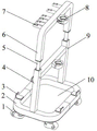
FIG. 1 is a schematic view of the overall structure of a cable receiving rack of the present invention;
FIG. 2 is a schematic view of the position relationship of the horizontal slide, the limiting groove and the plurality of cable hooks according to the present invention;
FIG. 3 is a schematic view of a missile test cable in a test condition;
FIG. 4 is a schematic view of the missile test cable in a stowed condition;
FIG. 5 is a schematic structural view of the cable holder;
the labels in the figure are: 1. universal wheel, 2, underframe, 3, limiting plate, 4, lower carriage, 5, guide post, 6, upper bracket, 7, cable couple, 8, cable fixing base, 801, go up annular seat, 802, lower annular seat, 803, solid fixed ring, 9, elasticity pin, 10, bottom plate, 11, dog, 12, horizontal slideway, 13, spacing groove, 14, card hole.
Detailed Description
In order to make the objects, technical solutions and advantages of the embodiments of the present invention clearer, the technical solutions in the embodiments of the present invention will be described clearly and completely with reference to the accompanying drawings in the present invention, and it is obvious that the described embodiments are some embodiments of the present invention, but not all embodiments, and all other embodiments obtained by a person of ordinary skill in the art based on the embodiments of the present invention without creative efforts belong to the protection scope of the present invention.
A cable storage support is shown in figure 1 and mainly comprises a chassis, a support frame, a cable fixing seat and a plurality of cable hooks.
Wherein, the chassis is by underframe 2, bottom plate 10, a plurality of universal wheel 1 is constituteed, underframe 2 is formed by the stainless steel pipe welding of bending, bottom plate 10 is corrosion resistant plate, this corrosion resistant plate of underframe 2's bottom welding, chassis bottom four feet department installation universal wheel 1, this universal wheel 1 is the universal castor of area brake, a rectangular hole is respectively processed to the intermediate position of 2 two curb girders of underframe, a support frame for the erection bracing frame, 2 upper portion four corners installation limiting plates 3 of underframe, and simultaneously, 2 four corners fillets of underframe prevent to cause the injury to the people.
The supporting frame is of a hierarchical structure and consists of an upper supporting frame 6 and a lower supporting frame 4, the upper supporting frame and the lower supporting frame are connected through a guide post 5, the guide post 5 is a stainless steel pipe, and the height can be adjusted by limiting through an elastic pin 9; the upper support and the lower support comprise vertical beams and cross beams, the vertical beams and the cross beams are formed by welding stainless steel tubes, and the cross beams are respectively provided with a cable fixing seat 8 for fixing a main cable of a branched cable; the bottom of the vertical beam of the lower bracket 4 can be inserted into a rectangular hole formed in the side beam of the bottom frame 2, so that the support frame and the chassis can be quickly mounted and dismounted; as shown in fig. 2, a plurality of cable hooks 7 are mounted on the beam of the upper bracket 6 for accommodating branch cables and providing restraint for the connectors of the branch cables, a horizontal slide 12 is disposed on the beam for achieving the best use effect, a plurality of limiting grooves 13 are equidistantly arranged at the bottom of the horizontal slide 12, the cable hooks 7 can move left and right in the horizontal slide 12 on the beam, and the limiting grooves 13 are used for limiting after the cable hooks are in place.
As shown in fig. 5, the cable fixing seat 8 mainly includes a fixing seat and a fixing ring 803, the fixing seat is installed on the beam of the upper and lower supports through screws, the fixing ring 803 is embedded in the fixing seat, the fixing seat is divided into an upper portion and a lower portion, which are respectively an upper annular seat 801 and a lower annular seat 802, one end of the upper annular seat and the lower annular seat is hinged through a pin, the free ends of the upper annular seat and the lower annular seat are connected in a snap-in manner, after the free ends of the upper annular seat and the lower annular seat are connected in a snap-in manner, the fixing ring is located on the inner side of the upper annular seat and can freely rotate along the inner walls of the upper annular seat and the lower annular seat, in the embodiment, the upper portion of the fixing seat is a movable.
As shown in fig. 3 and 4, when the cable testing device is used, a bifurcation point of a testing cable is firstly fixed in the cable fixing seat 8 positioned above to provide a fulcrum for a main cable, so that the stress of the cable connector of the bifurcation is avoided, and the main cable is fixed in the cable fixing seat 8 positioned below after being straightened. During testing, the branch cable reaches a product testing interface from the upper edge of the beam of the upper bracket 6; when the cable plug is stored, the cable plug at a product testing interface is pulled out, the branch cable is short, the plug can be directly restrained in the clamping hole 14 of the cable hook 7 in a U-shaped structure, the cable can be hung on the cable hook 7 after being coiled for one circle or two circles, the plug is restrained in the clamping hole 14 of the cable hook 7, finally, the main cable plug is pulled out from the testing equipment, the main cable plug is coiled into an oval shape around a vertical beam of a supporting frame, the cable is limited through a plurality of limiting plates 3 arranged at the top of a bottom frame 2, and finally, the main cable plug is placed on a chassis, namely, the cable is accommodated; the base plate 10 may also receive test accessories or tools.
When the device is not used, the missile test cable can be directly wound and then pushed to the storage area, and the universal wheels are locked through the brakes of the universal wheels, so that the support is prevented from moving; when the universal wheel unlocking device is used, the universal wheel can be directly pushed to the position near the missile to be quickly unfolded, the situation that the missile is stored and transported from an accessory box in a back-and-forth mode is avoided, the structure is simple, the design is reasonable, the testing efficiency is greatly improved, and the bifurcation point of a missile testing cable cannot be damaged.
The previous description of the disclosed embodiments is provided to enable any person skilled in the art to make or use the present invention. Various modifications to these embodiments will be readily apparent to those skilled in the art, and the generic principles defined herein may be applied to other embodiments without departing from the spirit or scope of the invention. Thus, the present invention is not intended to be limited to the embodiments shown herein but is to be accorded the widest scope consistent with the principles and novel features disclosed herein.
Claims (7)
1. The utility model provides a support is accomodate to cable, includes chassis, height-adjustable's support frame and installs a plurality of cable fixing bases on the support frame, its characterized in that: the chassis comprises a bottom frame and a plurality of universal wheels arranged at the bottom of the bottom frame, and a plurality of limiting plates for limiting the cables are arranged above the bottom frame at intervals;
the supporting frame comprises an upper supporting frame and a lower supporting frame, the lower supporting frame is arranged at the top of the bottom frame in a pluggable mode, the upper supporting frame is connected with the lower supporting frame through a guide column, cable fixing seats used for allowing cables to penetrate through and fixing the cables are respectively arranged on the upper supporting frame and the lower supporting frame, and the two cable fixing seats are distributed up and down; horizontal sliding ways are arranged on one side, not provided with the cable fixing seat, of the upper support in the horizontal direction, a plurality of limiting grooves communicated with the horizontal sliding ways are arranged at intervals in the bottom of the horizontal sliding ways, a plurality of cable hooks are arranged in the horizontal sliding ways in a sliding mode, and each cable hook can be clamped in the corresponding limiting groove after sliding to a preset position.
2. A cable storage rack according to claim 1, wherein: one end of the cable hook is of a trapezoidal structure matched with the limiting groove and the horizontal slide rail at the same time, the other end of the cable hook is provided with a clamping hole matched with the connector at the end part, the connector can be selectively clamped in the corresponding clamping hole, and a stop block is arranged at the top of the cable hook.
3. A cable storage rack according to claim 1, wherein: the underframe is formed by stainless steel pipe bending welding, and the bottom of underframe still is provided with the bottom plate, and a plurality of universal wheel distributes around the bottom plate.
4. A cable storage rack according to claim 3, wherein: the universal wheels are universal caster wheels with brakes.
5. A cable storage rack according to claim 1, wherein: the cable fixing seat comprises a lower annular seat detachably connected with the upper support or the lower support, an upper annular seat matched with the lower annular seat and a fixing ring embedded on the inner sides of the upper annular seat and the lower annular seat and used for fixing the cable, wherein one ends of the upper annular seat and the lower annular seat are hinged through a pin shaft, the free ends of the upper annular seat and the lower annular seat are connected in a buckling mode, and when the free ends of the upper annular seat and the lower annular seat are buckled and connected, the fixing ring is located on the inner sides of the upper annular seat and the lower annular seat and can freely rotate along the inner walls.
6. A cable take-up stand according to claim 5, wherein: and the free ends of the upper annular seat and the lower annular seat are respectively provided with a lock tongue and a lock catch which are matched with each other.
7. The cable storage rack of claim 6, wherein: the lower annular seat is installed on the upper support and the lower support through screws.
Priority Applications (1)
| Application Number | Priority Date | Filing Date | Title |
|---|---|---|---|
| CN202011100511.2A CN112299152B (en) | 2020-10-15 | 2020-10-15 | Cable storage bracket |
Applications Claiming Priority (1)
| Application Number | Priority Date | Filing Date | Title |
|---|---|---|---|
| CN202011100511.2A CN112299152B (en) | 2020-10-15 | 2020-10-15 | Cable storage bracket |
Publications (2)
| Publication Number | Publication Date |
|---|---|
| CN112299152A true CN112299152A (en) | 2021-02-02 |
| CN112299152B CN112299152B (en) | 2022-07-26 |
Family
ID=74327367
Family Applications (1)
| Application Number | Title | Priority Date | Filing Date |
|---|---|---|---|
| CN202011100511.2A Active CN112299152B (en) | 2020-10-15 | 2020-10-15 | Cable storage bracket |
Country Status (1)
| Country | Link |
|---|---|
| CN (1) | CN112299152B (en) |
Cited By (2)
| Publication number | Priority date | Publication date | Assignee | Title |
|---|---|---|---|---|
| CN113517092A (en) * | 2021-04-15 | 2021-10-19 | 白银有色长通电线电缆有限责任公司 | Trolley for pre-branch cable production |
| CN113872122A (en) * | 2021-11-01 | 2021-12-31 | 中船黄埔文冲船舶有限公司 | Multifunctional equipment mounting bracket |
Citations (8)
| Publication number | Priority date | Publication date | Assignee | Title |
|---|---|---|---|---|
| CN204896217U (en) * | 2015-08-04 | 2015-12-23 | 国家电网公司 | Frame is transported to earth bar |
| CN106229892A (en) * | 2016-08-08 | 2016-12-14 | 淮南矿业(集团)有限责任公司 | Combine pick cable self-moving device |
| CN206640278U (en) * | 2017-04-25 | 2017-11-14 | 国网安徽省电力公司安庆供电公司 | A kind of improved cable bearer |
| CN207896625U (en) * | 2017-12-27 | 2018-09-21 | 天津市正天东源电力电气设备有限公司 | A kind of hanging cable bearer of bar |
| CN208142787U (en) * | 2018-05-17 | 2018-11-23 | 国运电缆(天津)有限公司 | Aluminium alloy aerial insulated cable fixes device |
| CN210628988U (en) * | 2019-11-19 | 2020-05-26 | 李栋 | Cable support for municipal construction convenient to remove |
| CN210779883U (en) * | 2019-09-25 | 2020-06-16 | 浙江高隧修电缆挂架有限公司 | Novel cable hanging rack |
| CN210852445U (en) * | 2019-09-12 | 2020-06-26 | 中车洛阳机车有限公司 | Main circuit wiring device of locomotive |
-
2020
- 2020-10-15 CN CN202011100511.2A patent/CN112299152B/en active Active
Patent Citations (8)
| Publication number | Priority date | Publication date | Assignee | Title |
|---|---|---|---|---|
| CN204896217U (en) * | 2015-08-04 | 2015-12-23 | 国家电网公司 | Frame is transported to earth bar |
| CN106229892A (en) * | 2016-08-08 | 2016-12-14 | 淮南矿业(集团)有限责任公司 | Combine pick cable self-moving device |
| CN206640278U (en) * | 2017-04-25 | 2017-11-14 | 国网安徽省电力公司安庆供电公司 | A kind of improved cable bearer |
| CN207896625U (en) * | 2017-12-27 | 2018-09-21 | 天津市正天东源电力电气设备有限公司 | A kind of hanging cable bearer of bar |
| CN208142787U (en) * | 2018-05-17 | 2018-11-23 | 国运电缆(天津)有限公司 | Aluminium alloy aerial insulated cable fixes device |
| CN210852445U (en) * | 2019-09-12 | 2020-06-26 | 中车洛阳机车有限公司 | Main circuit wiring device of locomotive |
| CN210779883U (en) * | 2019-09-25 | 2020-06-16 | 浙江高隧修电缆挂架有限公司 | Novel cable hanging rack |
| CN210628988U (en) * | 2019-11-19 | 2020-05-26 | 李栋 | Cable support for municipal construction convenient to remove |
Cited By (2)
| Publication number | Priority date | Publication date | Assignee | Title |
|---|---|---|---|---|
| CN113517092A (en) * | 2021-04-15 | 2021-10-19 | 白银有色长通电线电缆有限责任公司 | Trolley for pre-branch cable production |
| CN113872122A (en) * | 2021-11-01 | 2021-12-31 | 中船黄埔文冲船舶有限公司 | Multifunctional equipment mounting bracket |
Also Published As
| Publication number | Publication date |
|---|---|
| CN112299152B (en) | 2022-07-26 |
Similar Documents
| Publication | Publication Date | Title |
|---|---|---|
| US5509671A (en) | Cart for carrying spools of wire | |
| CN112299152B (en) | Cable storage bracket | |
| KR20140029299A (en) | Loading/unloading apparatus | |
| CN110224356A (en) | Packaged type cable, spool bracket and its application method | |
| CN212608628U (en) | Combined cable reel bracket | |
| US20160159606A1 (en) | Field & Barbed Wire Unroller Apparatus | |
| CN212048561U (en) | Pipeline spare arrangement frame for building engineering | |
| CN209881304U (en) | Movable cable and conduit bracket | |
| EP0431226A1 (en) | Drive-on vehicle supporting arrangement | |
| SU1584014A1 (en) | Trolley for moving along wires of split phase of aerial power transmission line | |
| CN215711263U (en) | Quick replacing device for capacitor unit | |
| CN214780003U (en) | Pay-off rack for electric power construction | |
| CN214935749U (en) | Electric power overhauls uses construction platform | |
| CN208008175U (en) | A kind of engineering residue cable take-up | |
| CN220392973U (en) | Cable laying coiling and uncoiling device | |
| CN223132054U (en) | A metro section electromechanical installation and transportation operation vehicle | |
| CN216421368U (en) | Welding maintenance transport vehicle | |
| CN222181433U (en) | A wiring harness storage vehicle | |
| CN214958160U (en) | Portable electric box frame and power distribution equipment comprising same | |
| CN220467213U (en) | Pipeline laying device for municipal construction road construction | |
| CN112677870A (en) | Anti-extrusion equipment for transportation | |
| JP2924855B2 (en) | Cable retainer | |
| CN118597556B (en) | A pipe storage safety rack | |
| US4216931A (en) | Drying rack for fire hose | |
| KR102079927B1 (en) | Underground Cable Casting System and Construction Method |
Legal Events
| Date | Code | Title | Description |
|---|---|---|---|
| PB01 | Publication | ||
| PB01 | Publication | ||
| CB02 | Change of applicant information |
Address after: 471000 No.18, Qianjing South Road, high tech Development Zone, Luoyang area, China (Henan) pilot Free Trade Zone, Luoyang City, Henan Province Applicant after: CAMA (LUOYANG) MEASUREMENTS & CONTROLS Co.,Ltd. Applicant after: PLA 94833 unit Address before: 471000 No.2, Qianjing South Road, high tech Development Zone, Luoyang City, Henan Province Applicant before: CAMA (LUOYANG) MEASUREMENTS & CONTROLS Co.,Ltd. Applicant before: PLA 94833 unit |
|
| CB02 | Change of applicant information | ||
| SE01 | Entry into force of request for substantive examination | ||
| SE01 | Entry into force of request for substantive examination | ||
| GR01 | Patent grant | ||
| GR01 | Patent grant |