CN112260022A - Wall socket with jacks capable of adjusting angles - Google Patents
Wall socket with jacks capable of adjusting angles Download PDFInfo
- Publication number
- CN112260022A CN112260022A CN202011283739.XA CN202011283739A CN112260022A CN 112260022 A CN112260022 A CN 112260022A CN 202011283739 A CN202011283739 A CN 202011283739A CN 112260022 A CN112260022 A CN 112260022A
- Authority
- CN
- China
- Prior art keywords
- sets
- groups
- adjusting
- top surface
- clamping
- Prior art date
- Legal status (The legal status is an assumption and is not a legal conclusion. Google has not performed a legal analysis and makes no representation as to the accuracy of the status listed.)
- Granted
Links
- 230000001681 protective effect Effects 0.000 claims abstract description 23
- 238000003780 insertion Methods 0.000 claims description 34
- 230000037431 insertion Effects 0.000 claims description 34
- 239000002184 metal Substances 0.000 claims description 26
- 229910052751 metal Inorganic materials 0.000 claims description 26
- XEEYBQQBJWHFJM-UHFFFAOYSA-N Iron Chemical compound [Fe] XEEYBQQBJWHFJM-UHFFFAOYSA-N 0.000 claims description 6
- 239000000463 material Substances 0.000 claims description 6
- RYGMFSIKBFXOCR-UHFFFAOYSA-N Copper Chemical compound [Cu] RYGMFSIKBFXOCR-UHFFFAOYSA-N 0.000 claims description 4
- 229910052802 copper Inorganic materials 0.000 claims description 4
- 239000010949 copper Substances 0.000 claims description 4
- 229920006351 engineering plastic Polymers 0.000 claims description 3
- 229910052742 iron Inorganic materials 0.000 claims description 3
- 230000005611 electricity Effects 0.000 claims 18
- 238000010586 diagram Methods 0.000 description 5
- 230000004075 alteration Effects 0.000 description 1
- 238000009434 installation Methods 0.000 description 1
- 238000012986 modification Methods 0.000 description 1
- 230000004048 modification Effects 0.000 description 1
- 238000006467 substitution reaction Methods 0.000 description 1
Images






Classifications
-
- H—ELECTRICITY
- H01—ELECTRIC ELEMENTS
- H01R—ELECTRICALLY-CONDUCTIVE CONNECTIONS; STRUCTURAL ASSOCIATIONS OF A PLURALITY OF MUTUALLY-INSULATED ELECTRICAL CONNECTING ELEMENTS; COUPLING DEVICES; CURRENT COLLECTORS
- H01R27/00—Coupling parts adapted for co-operation with two or more dissimilar counterparts
-
- H—ELECTRICITY
- H01—ELECTRIC ELEMENTS
- H01R—ELECTRICALLY-CONDUCTIVE CONNECTIONS; STRUCTURAL ASSOCIATIONS OF A PLURALITY OF MUTUALLY-INSULATED ELECTRICAL CONNECTING ELEMENTS; COUPLING DEVICES; CURRENT COLLECTORS
- H01R13/00—Details of coupling devices of the kinds covered by groups H01R12/70 or H01R24/00 - H01R33/00
- H01R13/46—Bases; Cases
- H01R13/502—Bases; Cases composed of different pieces
-
- H—ELECTRICITY
- H01—ELECTRIC ELEMENTS
- H01R—ELECTRICALLY-CONDUCTIVE CONNECTIONS; STRUCTURAL ASSOCIATIONS OF A PLURALITY OF MUTUALLY-INSULATED ELECTRICAL CONNECTING ELEMENTS; COUPLING DEVICES; CURRENT COLLECTORS
- H01R13/00—Details of coupling devices of the kinds covered by groups H01R12/70 or H01R24/00 - H01R33/00
- H01R13/46—Bases; Cases
- H01R13/514—Bases; Cases composed as a modular blocks or assembly, i.e. composed of co-operating parts provided with contact members or holding contact members between them
-
- H—ELECTRICITY
- H01—ELECTRIC ELEMENTS
- H01R—ELECTRICALLY-CONDUCTIVE CONNECTIONS; STRUCTURAL ASSOCIATIONS OF A PLURALITY OF MUTUALLY-INSULATED ELECTRICAL CONNECTING ELEMENTS; COUPLING DEVICES; CURRENT COLLECTORS
- H01R13/00—Details of coupling devices of the kinds covered by groups H01R12/70 or H01R24/00 - H01R33/00
- H01R13/62—Means for facilitating engagement or disengagement of coupling parts or for holding them in engagement
- H01R13/627—Snap or like fastening
Landscapes
- Connector Housings Or Holding Contact Members (AREA)
Abstract
The invention relates to a wall socket with jacks capable of adjusting angles, which comprises an outer protective cover plate and a wiring base plate structure, wherein the outer protective cover plate is connected to the top surface of the wiring base plate structure, three flat holes, two outer adjusting rotary holes and an adjusting bolt outer rotary hole are formed in the top surface of the outer protective cover plate, the three flat holes are formed in the rear side of the top surface of the outer protective cover plate, the outer adjusting rotary holes are formed in two groups, the two outer adjusting rotary holes are formed in the front side of the top surface of the outer protective cover plate in parallel, and the adjusting bolt outer rotary hole is formed between the two outer adjusting rotary holes. The wall socket has the advantages that the arrangement of the wall socket is optimized, the structural layout adopted by the traditional wall socket is changed, the wall socket is improved into a design with jacks capable of rotating, not only can be inserted into an obliquely inserted three-hole plug, but also can be inserted into a directly inserted two-hole plug, and can be adjusted and used according to the standard sockets of different countries, the application range is wide, the structure adopts the design of a mechanical structure, and the wall socket is simple and durable and is suitable for popularization and use.
Description
Technical Field
The invention relates to the field of electric power, in particular to a wall socket with jacks capable of adjusting angles.
Background
The socket is also called as a power socket and a switch socket. A socket is a receptacle into which one or more circuit connections can be inserted, through which various connections can be inserted, thus facilitating the connection to other circuits. The connection and disconnection between the circuit and the copper piece are used for achieving the connection and disconnection of the part of circuit finally, the traditional socket on the market adopts a two-hole and three-hole insertion mode, the proper insertion position cannot be adjusted according to different plugs, and in order to enable the socket to be more suitable for the insertion of the plug, the wall socket with the jack capable of adjusting the angle is designed.
Disclosure of Invention
The invention aims to provide a wall socket with jacks capable of adjusting angles, which aims to solve the technical problems and adopts the following technical scheme for achieving the purpose:
the utility model provides a wall socket that jack can angle regulation, includes outer protective cover board, connection base plate structure, the top surface at connection base plate structure is connected to outer protective cover board, the top surface of outer protective cover board is equipped with three flat holes, outer regulation trompil, regulation bolt outer socket hole, three flat holes are seted up at outer protective cover board top surface rear side, two sets of have been seted up in outer regulation trompil, and two sets of outer regulation trompils are set up the top surface front side of protecting the cover board outside side by side, regulation bolt outer socket hole is seted up between two sets of outer regulation trompils.
On the basis of the technical scheme, the wire holder plate structure comprises a flat plug board, a power connection bottom box, power insertion rotary heads and angle adjusting bolts, wherein the flat plug board is fixed on the top surface of the power connection bottom box, the top surface of the flat plug board is provided with inner adjusting rotary holes, three flat holes, a seat board fixing hole and adjusting bolt inner inserting holes, the three flat holes are formed in the rear side of the top surface of the flat plug board, the inner adjusting rotary holes are formed in two groups, the two groups of inner adjusting rotary holes are arranged in parallel and formed in the front side of the top surface of the flat plug board, the seat board fixing holes are formed in four groups, the four groups of fixing holes are respectively formed in the edges of the flat plug board, the adjusting bolt inner inserting holes are formed between the two groups of inner adjusting rotary holes, the power insertion rotary heads are arranged in the power connection bottom box, the two groups of power insertion rotary heads penetrate through the two groups of inner adjusting rotary holes in the front side of the top surface of the flat plug, and the angle adjusting bolt passes through an inner inserting hole of the adjusting bolt on the front side of the top surface of the flat inserting plate.
On the basis of the technical scheme, the electric connection bottom box is internally provided with two groups of electric connection clamping pieces, two groups of electric conduction plates, an electric conduction plate, an adjusting structure and an electric conduction clamp structure, the two groups of electric conduction plates are arranged on the inner bottom side of the electric connection bottom box in parallel, the adjusting structure is arranged on the inner front side of the electric connection bottom box, the electric connection clamping pieces are provided with three groups, the two groups of electric connection clamping pieces are symmetrically arranged on the rear end top side of the electric conduction plate, one group of electric connection clamping pieces are arranged on the front side between the two groups of electric connection clamping pieces, the adjusting structure is provided with two groups of electric insertion rotary grooves and adjusting bolt grooves, the two groups of electric insertion rotary grooves are symmetrically arranged on the top surface of the adjusting structure, the adjusting bolt grooves are arranged between the two electric insertion rotary grooves, the two groups of electric insertion rotary grooves and the adjusting bolt grooves are mutually communicated, the electric conduction clamp structure is provided with two groups of electric conduction clamp, the two groups of conductive clamp structures are arranged on the top sides of the front ends of the two groups of conductive plates, the electric connection clamping pieces, the conductive plates and the conductive clamp structures are integrally formed, the two groups of electric insertion rotating heads are embedded in the two groups of electric insertion rotating grooves and can rotate in the electric insertion rotating grooves, the angle adjusting bolts are inserted in the adjusting bolt grooves and connected between the two groups of electric insertion rotating heads, three groups of wiring interfaces are arranged on the bottom surface of the electric connection bottom box, the two groups of wiring interfaces are symmetrically arranged on two sides of the bottom surface of the electric connection bottom box, one group of wiring interfaces are arranged on the front side between the two groups of wiring interfaces, and the three groups of wiring interfaces are respectively connected with the three groups of electric connection clamping pieces.
On the basis of the technical scheme, the power-inserting rotary head is composed of a rotary head shell and a metal rotary head, a clamping groove is formed in the rotary head shell, the metal rotary head is inserted in the bottom side of the clamping groove, inclined insections are formed in the outer side of the rotary head shell, the conductive clamp structure is connected to the bottom end of the metal rotary head, the metal rotary head is composed of two groups of power-clamping plate structures, a sliding plate structure and conductive columns, the two groups of power-clamping plate structures are symmetrically connected to the top surface of the sliding plate structure, the conductive columns are arranged on the bottom side surface of the sliding plate structure, the sliding plate structure and the conductive columns are integrally formed, the conductive clamp structure is connected to the bottom end of the conductive columns, and the conductive columns can rotate on the inner side of the conductive clamp structure.
On the basis of the technical scheme, electrically conductive clamp structure comprises fine motion pivot, interior clamp spring, arc inner splint, the arc inner splint is equipped with two sets ofly, and two sets of arc inner splint are the symmetry and establish, interior clamp spring is equipped with two sets ofly, and two sets of inner splint springs are the outside of establishing at two sets of arc inner splint of symmetry, the fine motion pivot is equipped with two sets ofly, and the rear end at arc inner splint is connected respectively to two sets of fine motion pivots, the front end at the current conducting plate is connected through the fine motion pivot to the arc inner splint.
On the basis of the technical scheme, the outer side surface of the angle adjusting bolt is provided with oblique insections, and the oblique insections on the outer side of the angle adjusting bolt are connected with the oblique insections on the outer side of the rotary head shell.
On the basis of the technical scheme, the electric clamping plate structure is composed of a sliding plate, a connecting lug, symmetrical clamping plates and opposite clamping springs, the sliding plate, the connecting lug and the symmetrical clamping plates are respectively provided with two groups and are oppositely arranged, the connecting lug is arranged on the top surface of the sliding plate, the symmetrical clamping plates are arranged on the top surface of the connecting lug, the sliding plate, the connecting lug and the symmetrical clamping plates are integrally formed, the opposite clamping springs are provided with four groups, the four groups of opposite clamping springs are symmetrically fixed on the outer side surfaces of the symmetrical clamping plates, the outer sides of the four groups of opposite clamping springs are fixed on the inner side walls of the clamping grooves, the sliding plate structure is composed of a supporting plate and an outward-protruding sliding groove, the outward-protruding sliding groove is arranged on the top surface of the supporting plate, the sliding.
On the basis of the technical scheme, the outer protective cover plate, the angle adjusting bolt, the rotary head shell are made of engineering plastics, the metal rotary head is made of a metal copper material, and the flat inserting plate and the electric connection bottom box are made of a metal iron material.
Compared with the prior art, the invention has the following advantages: the wall socket has the advantages that the arrangement of the wall socket is optimized, the structural layout adopted by the traditional wall socket is changed, the wall socket is improved into a design with jacks capable of rotating, not only can be inserted into an obliquely inserted three-hole plug, but also can be inserted into a directly inserted two-hole plug, and can be adjusted and used according to the standard sockets of different countries, the application range is wide, the structure adopts the design of a mechanical structure, and the wall socket is simple and durable and is suitable for popularization and use.
Drawings
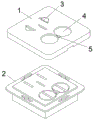
Fig. 1 is a general appearance state diagram of the present invention.
Fig. 2 is a schematic diagram of the cover plate of the present invention.
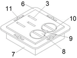
Fig. 3 is a schematic diagram of a wiring board structure according to the present invention.
Fig. 4 is a schematic view of the flat plug board of the present invention.
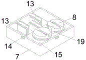
FIG. 5 is a schematic view of the electrical bottom box of the present invention.
FIG. 6 is a schematic diagram of the power connection bottom box according to the present invention.
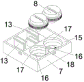
FIG. 7 is a schematic view of the bottom structure of the bottom box of the present invention.
FIG. 8 is a schematic view of a planar structure of the electrical bottom box of the present invention.
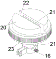
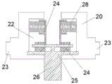
FIG. 9 is a schematic view of the plug-in swivel of the present invention.
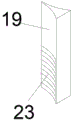
FIG. 10 is a schematic view of an angle adjustment bolt of the present invention.
FIG. 11 is a diagram of a conductive clip according to the present invention.
FIG. 12 is a schematic view of a metal swivel according to the present invention.
FIG. 13 is a schematic view of a structure of a clamping plate according to the present invention.
Fig. 14 is a schematic view of the structure of the slide plate of the present invention.
FIG. 15 is a schematic side plan view of the power plug of the present invention.
In the figure: the structure comprises an outer protective cover plate 1, a wire connection base plate structure 2, three flat holes 3, an outer adjusting rotary hole 4, an adjusting bolt outer inserting hole 5, a flat inserting plate 6, an electric connection bottom box 7, an electric insertion rotary head 8, an angle adjusting bolt 9, an inner adjusting rotary hole 10, a base plate fixing hole 11, an adjusting bolt inner inserting hole 12, an electric connection clamping piece 13, an electric conduction plate 14, an adjusting structure 15, an electric conduction clamp structure 16, an electric insertion rotary groove 17, an adjusting bolt groove 18, a wire connection interface 19, a rotary head shell 20, a metal rotary head 21, a clamping groove 22, inclined insections 23, an electric clamping plate structure 24, a sliding plate structure 25, a conductive post 26, a micro-motion rotary shaft 27, an inner clamping spring 28, an arc-shaped inner clamping plate 29, a sliding plate 30, a connecting bump 31, a symmetrical clamping plate 32, a butt-clamping spring 33.
Detailed Description
The invention is described in further detail below with reference to the figures and the detailed description.
The utility model provides a wall socket that jack can angle regulation, includes outer protective cover board 1, connection base plate structure 2, the top surface at connection base plate structure 2 is connected to outer protective cover board 1, the top surface of outer protective cover board 1 is equipped with three flat holes 3, outer regulation turning hole 4, adjusting bolt outer plug hole 5, three flat holes 3 are seted up and are being in outer protective cover board 1 top surface rear side, outer regulation turning hole 4 has seted up two sets ofly, and two sets of outer regulation turning holes 4 set up the top surface front side at outer protective cover board 1 side by side, adjusting bolt outer plug hole 5 sets up and adjusts between turning hole 4 two sets of.
The wiring base plate structure 2 comprises a flat plug board 6, a power connection bottom box 7, power insertion rotary heads 8 and angle adjusting bolts 9, wherein the flat plug board 6 is fixed on the top surface of the power connection bottom box 7, the top surface of the flat plug board 6 is provided with inner adjusting rotary holes 10, three flat holes 3, base plate fixing holes 11 and inner inserting holes 12 of the adjusting bolts, the three flat holes 3 are arranged on the rear side of the top surface of the flat plug board 6, the inner adjusting rotary holes 10 are provided with two groups, the two groups of inner adjusting rotary holes 10 are arranged in parallel and arranged on the front side of the top surface of the flat plug board 6, the base plate fixing holes 11 are provided with four groups, the four groups of base plate fixing holes 11 are respectively arranged on the edge of the flat plug board 6, the inner inserting holes 12 of the adjusting bolts are arranged between the two groups of inner adjusting rotary holes 10, the power insertion rotary heads 8 are provided with two groups, the two groups of power insertion rotary heads 8 are respectively arranged in the power connection bottom box 7, and the two groups of, the angle adjusting bolt 9 is arranged in the electric connection bottom box 7, and the angle adjusting bolt 9 penetrates through an adjusting bolt inner inserting hole 12 in the front side of the top surface of the flat inserting plate 6.
The electric connection bottom box 7 is internally provided with two groups of electric connection clamping pieces 13, two groups of electric conduction plates 14, an electric conduction plate 14, an adjusting structure 15 and an electric conduction clamp structure 16, the electric conduction plates 14 are arranged in parallel at the inner bottom side of the electric connection bottom box 7, the adjusting structure 15 is arranged at the front side of the inner part of the electric connection bottom box 7, the electric connection clamping pieces 13 are provided with three groups, the two groups of electric connection clamping pieces 13 are symmetrically arranged at the top side of the rear end of the electric conduction plate 14, one group of electric connection clamping pieces 13 are arranged at the front side between the two groups of electric connection clamping pieces 13, the adjusting structure 15 is provided with two groups of electric insertion rotary slots 17 and adjusting bolt slots 18, the electric insertion rotary slots 17 are symmetrically arranged at the top surface of the adjusting structure 15, the adjusting bolt slots 18 are arranged between the two electric insertion rotary slots 17, the two groups of electric insertion rotary slots 17 are mutually communicated with the adjusting bolt slots 18, the electric conduction clamp structure 16 is provided with two groups, and the two groups of electric conduction clamp structures 16, two groups of conductive clamp structures 16 are arranged on the top sides of the front ends of two groups of conductive plates 14, the electric connection clamping pieces 13, the conductive plates 14 and the conductive clamp structures 16 are integrally formed, two groups of electric insertion rotary heads 8 are embedded in two groups of electric insertion rotary grooves 17, the electric insertion rotary heads 8 can rotate in the electric insertion rotary grooves 17, the angle adjusting bolts 9 are inserted in the adjusting bolt grooves 18, the angle adjusting bolts 9 are connected between the two groups of electric insertion rotary heads 8, three groups of wiring interfaces 19 are arranged on the bottom surface of the electric connection bottom box 7, the two groups of wiring interfaces 19 are symmetrically arranged on two sides of the bottom surface of the electric connection bottom box 7, one group of wiring interfaces 19 are arranged on the front side between the two groups of wiring interfaces 19, and the three groups of wiring interfaces 19 are respectively connected with the three groups of.
The plug-in swivel 8 comprises a swivel shell 20 and a metal swivel 21, a clamping groove 22 is formed in the swivel shell 20, the metal swivel 21 is plugged at the bottom side of the clamping groove 22, inclined insections 23 are formed in the outer side of the swivel shell 20, the conductive clamp structure 16 is connected to the bottom end of the metal swivel 21, the metal swivel 21 comprises a clamping plate structure 24, a sliding plate structure 25 and conductive posts 26, the clamping plate structure 24 is provided with two groups, the two groups of clamping plate structures 24 are symmetrically connected to the top surface of the sliding plate structure 25, the conductive posts 26 are arranged on the bottom side surface of the sliding plate structure 25, the sliding plate structure 25 and the conductive posts 26 are integrally formed, the conductive clamp structure 16 is connected to the bottom end of the conductive posts 26, and the conductive posts 26 can rotate on the inner side of the conductive clamp structure 16.
Electrically conductive clamp structure 16 comprises splint 29 in fine motion pivot 27, interior clamp spring 28, the arc, splint 29 is equipped with two sets ofly in the arc, and splint 29 is the symmetry in two sets of arcs and establishes, interior clamp spring 28 is equipped with two sets ofly, and two sets ofly interior clamp spring 28 is the outside of establishing splint 29 in two sets of arcs of symmetry, fine motion pivot 27 is equipped with two sets ofly, and splint 29's rear end in the arc is connected respectively to two sets of fine motion pivots 27, splint 29 connects the front end at current conducting plate 14 through fine motion pivot 27 in the arc.
The outer side surface of the angle adjusting bolt 9 is provided with oblique insections 23, and the oblique insections 23 on the outer side of the angle adjusting bolt 9 are connected with the oblique insections 23 on the outer side of the rotary head shell 20.
The electric board clamping structure 24 is composed of a sliding board 30, a connecting bump 31, symmetrical clamping boards 32 and oppositely clamped springs 33, the sliding board 30, the connecting bump 31 and the symmetrical clamping boards 32 are provided with two sets and are oppositely arranged, the connecting bump 31 is arranged on the top surface of the sliding board 30, the symmetrical clamping boards 32 are arranged on the top surface of the connecting bump 31, the sliding board 30, the connecting bump 31 and the symmetrical clamping boards 32 are integrally formed, the oppositely clamped springs 33 are provided with four sets, the four sets of the oppositely clamped springs 33 are symmetrically fixed on the outer side surfaces of the symmetrical clamping boards 32, the outer sides of the four sets of the oppositely clamped springs 33 are fixed on the inner side walls of the clamping grooves 22, the sliding board structure 25 is composed of a support board 34 and an outward convex sliding groove 35, the outward convex sliding groove 35 is arranged on the top surface of the support board 34, the sliding board 30 is inserted into the outward convex.
The outer protective cover plate 1, the angle adjusting bolt 9, the swivel shell 20 are made of engineering plastics, the metal swivel 21 is made of a metal copper material, and the flat inserting plate 6 and the electric connection bottom box 7 are made of a metal iron material.
The working principle of the invention is as follows: the installation and the use mode of the socket are the same, the specific difference is that the internal electric connection bottom box has different structures, the electric insertion rotary head in the electric connection bottom box can adjust the angle to adapt to plugs with different standards, the depth and the depth of the angle adjusting bolt are manually adjusted, the rotation of the electric insertion rotary head is further adjusted, the inclined insection on the side surface of the angle adjusting bolt is connected with the inclined insection on the outer side of the rotary head shell, the angle adjusting bolt drives the rotary head shell to rotate when moving downwards or downwards, the metal rotary head in the rotary head shell can rotate, no matter how the metal rotary head rotates, the conductive column is always contacted in the electric clamping plate structure and keeps electrified, when the plug is inserted, the plug is firstly contacted with the symmetrical clamping plates, the symmetrical clamping plates slide on the outer convex sliding grooves, the opposite clamping springs are further compressed, the plug is clamped between the symmetrical clamping plates, and the plug insertion at any angle is kept, the angle of the rotary head shell and the metal rotary head can be adjusted only by adjusting the height position of the angle adjusting bolt, so that the socket can adapt to more plugs, and the multipurpose performance of the socket is realized.
The foregoing is a preferred embodiment of the present invention, and it will be apparent to those skilled in the art that variations, modifications, substitutions and alterations can be made in the embodiment without departing from the principles and spirit of the invention.
Claims (8)
1. The utility model provides a wall socket that jack can angle regulation, a serial communication port, including outer protective cover board (1), connection base plate structure (2), the top surface at connection base plate structure (2) is connected in outer protective cover board (1), the top surface of outer protective cover board (1) is equipped with three flat holes (3), outer regulation turning hole (4), adjusting bolt outer plug hole (5), flat three holes (3) are seted up and are being in outer protective cover board (1) top surface rear side, two sets of have been seted up in outer regulation turning hole (4), and two sets of outer regulation turning hole (4) are seted up and are being in outer protective cover board's (1) top surface front side by side, adjusting bolt outer plug hole (5) are seted up and are being adjusted between turning hole (4) two sets of.
2. The wall socket with the angle-adjustable jacks according to claim 1, wherein the wire connection seat plate structure (2) comprises a flat plug board (6), a power connection bottom box (7), a power connection rotating head (8) and an angle adjusting bolt (9), the flat plug board (6) is fixed on the top surface of the power connection bottom box (7), the top surface of the flat plug board (6) is provided with inner adjusting rotating holes (10), three flat holes (3), seat plate fixing holes (11) and inner inserting holes (12) of the adjusting bolt, the three flat holes (3) are arranged on the rear side of the top surface of the flat plug board (6), the inner adjusting rotating holes (10) are arranged in two groups, the two groups of inner adjusting rotating holes (10) are arranged in parallel and arranged on the front side of the top surface of the flat plug board (6), the seat plate fixing holes (11) are arranged in four groups, the four groups of seat plate fixing holes (11) are respectively arranged on the edges of the flat plug board (6), insert in the regulation bolt hole (12) set up in two sets of adjust between commentaries on classics hole (10), it is equipped with two sets ofly to insert electric swivel (8), and two sets of electricity swivels (8) of inserting are established respectively and are being met inside end box (7), and two sets of electricity swivels (8) of inserting are passed and are adjusted in two sets of commentaries on classics hole (10) of flat picture peg (6) top front side, angle adjusting bolt (9) are established and are being met in end box (7), and angle adjusting bolt (9) pass in the adjusting bolt hole (12) of flat picture peg (6) top front side.
3. The wall socket with the angle-adjustable jacks according to claims 1 and 2, wherein the power connection bottom box (7) is internally provided with power connection clamping pieces (13), current conducting plates (14), an adjusting structure (15) and a current conducting clamp structure (16), the current conducting plates (14) are provided with two sets, the two sets of current conducting plates (14) are arranged in parallel on the inner bottom side of the power connection bottom box (7), the adjusting structure (15) is arranged on the front side inside the power connection bottom box (7), the power connection clamping pieces (13) are provided with three sets, the two sets of power connection clamping pieces (13) are symmetrically arranged on the top side of the rear end of the current conducting plates (14), one set of power connection clamping pieces (13) is arranged on the front side between the two sets of power connection clamping pieces (13), the adjusting structure (15) is provided with power insertion rotary slots (17) and adjusting bolt slots (18), the power insertion rotary slots (17) are provided with two sets, the two sets of power insertion rotary slots (17) are symmetrically arranged on the top, the adjusting bolt grooves (18) are formed between the two electricity inserting rotary grooves (17), the two electricity inserting rotary grooves (17) are communicated with the adjusting bolt grooves (18), the electricity conducting clamp structures (16) are provided with two groups, the two electricity conducting clamp structures (16) are symmetrically arranged at the bottoms of the electricity inserting rotary grooves (17) in the adjusting structures (15), the two electricity conducting clamp structures (16) are arranged on the top sides of the front ends of the two electricity conducting plates (14), the electricity connecting clamping pieces (13), the electricity conducting plates (14) and the electricity conducting clamp structures (16) are integrally formed, the two electricity inserting rotary heads (8) are embedded in the two electricity inserting rotary grooves (17), the electricity inserting rotary heads (8) can rotate in the electricity inserting rotary grooves (17), the angle adjusting bolts (9) are inserted in the adjusting bolt grooves (18), the angle adjusting bolts (9) are connected between the two electricity inserting rotary heads (8), and three groups of wiring interfaces (19) are arranged on the bottom surface of the electricity connecting bottom box (7), two sets of wiring interfaces (19) are the bottom surface both sides of establishing in connecing electric end box (7) of symmetry, and front side between two sets of wiring interfaces (19) is established in a set of wiring interface (19), three sets of wiring interfaces (19) are connected three sets respectively and are connect electric clamping piece (13).
4. The wall socket with the plug hole capable of adjusting the angle as claimed in claims 1 and 2, wherein the plug electric swivel (8) comprises a swivel case (20) and a metal swivel (21), a clamping groove (22) is formed in the swivel case (20), the metal swivel (21) is plugged at the bottom side of the clamping groove (22), inclined teeth (23) are formed on the outer side of the swivel case (20), the conductive clamp structure (16) is connected to the bottom end of the metal swivel (21), the metal swivel (21) comprises two groups of electric clamping plate structures (24), a sliding plate structure (25) and conductive posts (26), the two groups of electric clamping plate structures (24) are symmetrically connected to the top surface of the sliding plate structure (25), the conductive posts (26) are arranged on the bottom side surface of the sliding plate structure (25), and the sliding plate structure (25), The conductive column (26) is integrally formed, the conductive clip structure (16) is connected to the bottom end of the conductive column (26), and the conductive column (26) can rotate inside the conductive clip structure (16).
5. The wall socket with the jack capable of adjusting the angle as claimed in claims 1, 2 and 3, wherein the conductive clip structure (16) is composed of a micro-motion rotating shaft (27), an inner clip spring (28) and an arc-shaped inner clip plate (29), the arc-shaped inner clip plate (29) is provided with two sets of inner clip plates (29), the two sets of inner clip springs (28) are symmetrically arranged at the outer sides of the two sets of arc-shaped inner clip plates (29), the micro-motion rotating shaft (27) is provided with two sets of inner clip springs (28), the two sets of micro-motion rotating shaft (27) are respectively connected at the rear ends of the arc-shaped inner clip plates (29), and the arc-shaped inner clip plate (29) is connected at the front end of the conductive plate (14) through the micro-motion rotating shaft (27).
6. The wall socket with the jack capable of adjusting the angle is characterized in that an inclined insection (23) is formed on the outer side surface of the angle adjusting bolt (9), and the inclined insection (23) on the outer side of the angle adjusting bolt (9) is connected with the inclined insection (23) on the outer side of the rotary head shell (20).
7. The wall socket with the jacks capable of adjusting the angle is characterized in that the electric clamping plate structure (24) consists of a sliding plate (30), a connecting lug (31), symmetrical clamping plates (32) and opposite clamping springs (33), the sliding plate (30), the connecting lug (31) and the symmetrical clamping plates (32) are respectively provided with two groups and are oppositely arranged, the connecting lug (31) is arranged on the top surface of the sliding plate (30), the symmetrical clamping plates (32) are arranged on the top surface of the connecting lug (31), the sliding plate (30), the connecting lug (31) and the symmetrical clamping plates (32) are integrally formed, the opposite clamping springs (33) are provided with four groups, the four groups of the opposite clamping springs (33) are symmetrically fixed on the outer side surfaces of the symmetrical clamping plates (32), the outer sides of the four groups of the opposite clamping springs (33) are fixed on the inner side walls of the clamping grooves (22), and the sliding plate structure (25) is formed by a support plate (34), The outer convex sliding groove (35) is arranged on the top surface of the carrier plate (34), the sliding plate (30) is inserted in the outer convex sliding groove (35), and the sliding plate (30) can slide in the outer convex sliding groove (35).
8. The wall socket with the angle-adjustable jacks is characterized in that the outer protective cover plate (1), the angle adjusting bolt (9) and the swivel shell (20) are made of engineering plastics, the metal swivel (21) is made of a metal copper material, and the flat plug board (6) and the electric bottom box (7) are made of a metal iron material.
Priority Applications (1)
| Application Number | Priority Date | Filing Date | Title |
|---|---|---|---|
| CN202011283739.XA CN112260022B (en) | 2020-11-17 | 2020-11-17 | Wall socket with jacks capable of adjusting angles |
Applications Claiming Priority (1)
| Application Number | Priority Date | Filing Date | Title |
|---|---|---|---|
| CN202011283739.XA CN112260022B (en) | 2020-11-17 | 2020-11-17 | Wall socket with jacks capable of adjusting angles |
Publications (2)
| Publication Number | Publication Date |
|---|---|
| CN112260022A true CN112260022A (en) | 2021-01-22 |
| CN112260022B CN112260022B (en) | 2022-06-03 |
Family
ID=74265863
Family Applications (1)
| Application Number | Title | Priority Date | Filing Date |
|---|---|---|---|
| CN202011283739.XA Active CN112260022B (en) | 2020-11-17 | 2020-11-17 | Wall socket with jacks capable of adjusting angles |
Country Status (1)
| Country | Link |
|---|---|
| CN (1) | CN112260022B (en) |
Cited By (1)
| Publication number | Priority date | Publication date | Assignee | Title |
|---|---|---|---|---|
| CN117878657A (en) * | 2021-11-15 | 2024-04-12 | 王永明 | Rotatable jack socket and rotary and storage jack socket |
Citations (12)
| Publication number | Priority date | Publication date | Assignee | Title |
|---|---|---|---|---|
| CN201498743U (en) * | 2009-07-07 | 2010-06-02 | 胡元成 | Multifunctional wall socket |
| CN202042772U (en) * | 2011-04-11 | 2011-11-16 | 马鑫 | Rotatable socket |
| DE102010050350A1 (en) * | 2010-11-05 | 2012-05-10 | Geka Gmbh | Connection socket device for e.g. vehicle trailer, has socket unit wired with set of output socket units for plug-connection with electrical devices of vehicle trailer, where output socket units are fastened to carrier plate with apertures |
| CN203085810U (en) * | 2013-02-02 | 2013-07-24 | 广州市沅子工业产品设计有限公司 | Two/three-hole conversion socket |
| TW201535895A (en) * | 2014-03-14 | 2015-09-16 | Sheng-Hsin Liao | Wall socket with connecting module |
| CN205069995U (en) * | 2015-11-16 | 2016-03-02 | 西安外事学院 | Intelligent domestic wall body socket of protection against electric shock thing networking with infrared induction |
| CN205646397U (en) * | 2016-05-20 | 2016-10-12 | 广东百事泰电子商务股份有限公司 | Rotatory multi -use socket of intelligent recognition |
| CN206022709U (en) * | 2016-08-31 | 2017-03-15 | 温州市龙洋电器有限公司 | A kind of wall socket |
| CN206059734U (en) * | 2016-08-31 | 2017-03-29 | 宋晓晖 | A kind of Combined plug bush |
| CN208368782U (en) * | 2018-07-10 | 2019-01-11 | 阿乐乐可湖北科技有限公司 | A kind of variable receptacle sockets |
| CN110148864A (en) * | 2019-05-26 | 2019-08-20 | 张政清 | A kind of environmental protection socket |
| CN210201084U (en) * | 2019-06-14 | 2020-03-27 | 苏州言信洁净工程有限公司 | Socket mounting structure for building metal purification plate |
-
2020
- 2020-11-17 CN CN202011283739.XA patent/CN112260022B/en active Active
Patent Citations (12)
| Publication number | Priority date | Publication date | Assignee | Title |
|---|---|---|---|---|
| CN201498743U (en) * | 2009-07-07 | 2010-06-02 | 胡元成 | Multifunctional wall socket |
| DE102010050350A1 (en) * | 2010-11-05 | 2012-05-10 | Geka Gmbh | Connection socket device for e.g. vehicle trailer, has socket unit wired with set of output socket units for plug-connection with electrical devices of vehicle trailer, where output socket units are fastened to carrier plate with apertures |
| CN202042772U (en) * | 2011-04-11 | 2011-11-16 | 马鑫 | Rotatable socket |
| CN203085810U (en) * | 2013-02-02 | 2013-07-24 | 广州市沅子工业产品设计有限公司 | Two/three-hole conversion socket |
| TW201535895A (en) * | 2014-03-14 | 2015-09-16 | Sheng-Hsin Liao | Wall socket with connecting module |
| CN205069995U (en) * | 2015-11-16 | 2016-03-02 | 西安外事学院 | Intelligent domestic wall body socket of protection against electric shock thing networking with infrared induction |
| CN205646397U (en) * | 2016-05-20 | 2016-10-12 | 广东百事泰电子商务股份有限公司 | Rotatory multi -use socket of intelligent recognition |
| CN206022709U (en) * | 2016-08-31 | 2017-03-15 | 温州市龙洋电器有限公司 | A kind of wall socket |
| CN206059734U (en) * | 2016-08-31 | 2017-03-29 | 宋晓晖 | A kind of Combined plug bush |
| CN208368782U (en) * | 2018-07-10 | 2019-01-11 | 阿乐乐可湖北科技有限公司 | A kind of variable receptacle sockets |
| CN110148864A (en) * | 2019-05-26 | 2019-08-20 | 张政清 | A kind of environmental protection socket |
| CN210201084U (en) * | 2019-06-14 | 2020-03-27 | 苏州言信洁净工程有限公司 | Socket mounting structure for building metal purification plate |
Cited By (1)
| Publication number | Priority date | Publication date | Assignee | Title |
|---|---|---|---|---|
| CN117878657A (en) * | 2021-11-15 | 2024-04-12 | 王永明 | Rotatable jack socket and rotary and storage jack socket |
Also Published As
| Publication number | Publication date |
|---|---|
| CN112260022B (en) | 2022-06-03 |
Similar Documents
| Publication | Publication Date | Title |
|---|---|---|
| CN201365322Y (en) | Distribution frame structure | |
| CN207853108U (en) | A kind of rail mounted mobile power socket device | |
| TWM267717U (en) | Assembly of rotatable receptacles | |
| WO2016018205A1 (en) | Docking station with rotatable multi-plug connector | |
| CN112260022B (en) | Wall socket with jacks capable of adjusting angles | |
| CN216598299U (en) | Socket assembly | |
| CN201674087U (en) | Rotating changeover plug | |
| JP3242826U (en) | rotary sockets and power strips | |
| CN112260021A (en) | Multifunctional adjustable wall socket | |
| CN203813172U (en) | Novel conversion socket | |
| CN219498428U (en) | Angle-adjustable electric connector | |
| CN111585100B (en) | Socket with improved structure | |
| CN220324889U (en) | Rotatable electric patch board | |
| CN105914511A (en) | Mobile socket with rotary bases, and manufacturing method for mobile socket | |
| CN219498371U (en) | Universal adapter with adjustable plugging angle | |
| CN214337001U (en) | Multi-direction rotatory socket structure | |
| CN212435286U (en) | Concealed junction box for power engineering | |
| CN218997253U (en) | Back lock type FPC connector | |
| CN207611935U (en) | A kind of socket of fast disassembly type | |
| CN222338740U (en) | Rotary track adapter | |
| CN217281337U (en) | Rotatable unit structure of socket hole | |
| CN220107126U (en) | Power supply rail | |
| CN219286838U (en) | Rotatable four-sided plugboard | |
| CN223502354U (en) | Double-row rotating power strip | |
| CN219610788U (en) | Guide rail socket |
Legal Events
| Date | Code | Title | Description |
|---|---|---|---|
| PB01 | Publication | ||
| PB01 | Publication | ||
| SE01 | Entry into force of request for substantive examination | ||
| SE01 | Entry into force of request for substantive examination | ||
| GR01 | Patent grant | ||
| GR01 | Patent grant | ||
| TR01 | Transfer of patent right |
Effective date of registration: 20230417 Address after: 528000 42 Leliu Gongye 4th Road, Shunde District, Foshan City, Guangdong Province Patentee after: FOSHAN SHUNDE MANFANG ELECTRIC INDUSTRIAL Co.,Ltd. Address before: Room 069a, 15th floor, building 1, digital life, No.8, Keji 5th Road, Zhangba Street office, high tech Zone, Xi'an City, Shaanxi Province, 710000 Patentee before: Xi'an Wenmo Electronic Technology Co.,Ltd. |
|
| TR01 | Transfer of patent right |