Electric appliance control module body and modularized manual and automatic integrated isolation and breaking device
Technical Field
The invention relates to an electric appliance control module body and a modularized manual and automatic integrated isolation and breaking device, and belongs to the technical field of mining explosion-proof vacuum feed switches.
Background
The mining explosion-proof vacuum feed switch is a device used for feed control and protection of a low-voltage power supply and distribution system under a coal mine, and plays an important role in the safety, reliability and rationality of power supply and protection.
Traditional feed switch, inside circuit breaker, current transformer, electrical component such as power transformer all is direct mount in the switch owner intracavity, when the switch breaks down and needs the maintenance, must stop the last level power supply, and the inner space is narrow and small, it is very difficult with the installation electrical component to change, waste time and energy simultaneously, for solving traditional feed switch maintenance, change and installation electrical component difficulty, there is not obvious disconnection point, the problem that waste time and energy simultaneously, provide an electrical control module body and the manual automatic integrative isolation breaking device of modularization.
Disclosure of Invention
According to the defects in the prior art, the technical problems to be solved by the invention are as follows: in order to solve one of the problems, the electrical appliance control module body and the modularized manual and automatic integrated isolation and breaking device are provided.
The invention discloses an electric appliance control module body, which is characterized in that: including the electrical apparatus control module box, install permanent magnetism vacuum circuit breaker in the electrical apparatus control module box, the handle has on the roof of electrical apparatus control module box, curb plate is for dismantling the curb plate about the electrical apparatus control module box, have the electrically conductive copper bar plug of output on the backplate of electrical apparatus control module box, and the electrically conductive copper bar of output is connected with the inside permanent magnetism vacuum circuit breaker of electrical apparatus control module box.
Preferably, the bottom of the electrical control module box body is provided with a positioning hole, and the electrical control module box body is internally provided with a leakage detection device, a permanent magnet device and a protector.
The invention relates to a modularized manual-automatic integrated isolation and breaking device, which comprises an electric appliance control module body and a main body breaking bracket module, wherein the electric appliance control module body is arranged on the main body breaking bracket module, the main body breaking bracket module comprises a base, the front end of the lower surface of the base is provided with an installation vertical plate A and an installation vertical plate B which are parallel to each other, the rear end of the lower surface of the base is provided with a driving motor, two parallel sliding optical axes A are arranged between the installation vertical plate A and the installation vertical plate B, a lead screw is arranged between the two sliding optical axes A, the front end of the lead screw is rotatably connected with the installation vertical plate A, the end part of the lead screw penetrates through the installation vertical plate A to be connected with a manual regulation meshing gear, the tail end of the lead screw is rotatably connected with the installation vertical plate B, the end part of the lead screw penetrates through, the two ends of the screw nut are respectively arranged on the corresponding sliding optical axes A in a sliding mode, the upper surface of the base is provided with a supporting plate device used for supporting the electric appliance control module body, the supporting plate device can slide relative to the base, the tail of the base is provided with a butt-inserting tailstock, and the screw nut is fixedly connected with the supporting plate device.
Preferably, the layer board device is including installing preceding backup pad and two slip optical axis B that are parallel to each other at base upper surface front end, slip optical axis B's front end is fixed in the backup pad before, slip optical axis B's tail end is fixed in the bottom of inserting the tailstock, and every slip optical axis B goes up to slide respectively and is provided with a sliding sleeve, the afterbody at the bottom surface of layer board is fixed to the sliding sleeve, the upper surface of layer board has the electrical control module body connecting seat that is used for fixed electrical control module body, and screw nut passes through a connecting rod and sliding sleeve or layer board fixed connection.
Preferably, edge guide rails are further arranged on two sides of the upper supporting plate, the cross section of each edge guide rail is circular and is arranged along the length direction of the upper supporting plate, guide wheel devices matched with the edge guide rails are respectively arranged at two ends of the front end of the upper supporting plate, and the guide wheel devices are fixedly mounted on the upper surface of the base.
Preferably, the opposite plug seat is also provided with side guard plates on two sides.
Preferably, the middle part of the base is provided with a long hole for the connecting rod to pass through so as to avoid interference.
Preferably, the plug-in seat is provided with a plurality of contact letter connectors which are matched with the plug on the electric appliance control module body.
Preferably, the front end of the upper supporting plate is provided with a handle.
The connecting seat of the electric appliance control module body is provided with a positioning pin which is matched with a positioning hole on the electric appliance control module body.
Preferably, still include outside manual control action bars assembly, the electrical box of operation control is located the one side of the disconnected bracket module of main part, and the disconnected bracket module of electrical apparatus control module body, main part, the electrical box of operation control are all installed inside explosion-proof housing, outside manual control action bars assembly is installed outside explosion-proof housing, operation control electrical box and driving motor electric connection.
Preferably, the external manual control operating rod assembly comprises an installation fixing plate, a manual and automatic interchange switch and a manual adjusting switch which are installed on the outer side of the installation fixing plate, and a sliding frame installed on the other side of the installation fixing plate, wherein two ends of the sliding frame are respectively arranged on a sliding rod A and a sliding rod B in a sliding manner, the inner ends of the sliding rod A and the sliding rod B are fixed on the inner side surface of the installation fixing plate, a bearing seat is installed at one end of the sliding frame, a gear shaft is installed on the sliding frame in a rotating manner through the bearing seat, a gear is arranged at one end of the gear shaft, a jack is arranged at the other end of the gear shaft, a rotating rod is arranged on the manual adjusting switch in a rotating manner, the inner end of the rotating rod penetrates through the installation fixing plate and the sliding frame to be inserted into the jack, so that the rotating rod is inserted into the jack or pulled out of the jack, and the combination or disconnection action of the gear shaft and the rotating rod is realized.
Preferably, the manual-automatic interchanging switch and the manual adjusting switch are integrally arranged.
Preferably, the manual-automatic interchanging switch is provided with a jack, a poking rod is inserted into the jack, one end of the poking rod is in sliding fit with the jack, and the outer end of the poking rod is pressed or pulled through external force so as to realize the relative telescopic action of the poking rod relative to the manual-automatic interchanging switch.
Preferably, the manual-automatic interchanging switch is provided with a poking rod, one end of the poking rod is rotatably connected with the manual-automatic interchanging switch, the inner end of the poking rod is provided with a thread section, the sliding frame is provided with a thread sleeve connected with the thread section, and the poking rod is controlled to rotate and rotate so as to realize the relative telescopic action of the poking rod relative to the thread sleeve.
Preferably, the section of the insertion end of the rotating rod is non-circular, in particular polygonal.
Preferably, the inner wall of the installation fixing plate is further provided with a shifting piece for limiting the rotation of the rotating rod, and the outer wall of the installation fixing plate is provided with a door lock and an unlocking switch for driving the shifting piece to ascend and descend so as to realize unlocking and locking of the rotating rod.
Compared with the prior art, the invention has the following beneficial effects:
according to the electrical control module body, the electrical control module body is designed into a novel electrical control module body by combining the independent protector device, the electric leakage detection device, the permanent magnet circuit device and all connecting plug type designs, and the product has the required functions and is comprehensive and integrated.
The modularized manual and automatic integrated isolation and breaking device is integrally designed in structure, convenient to use and convenient to replace and maintain.
The modularized manual and automatic integrated isolation and breaking device has complete functions and can realize various functions which cannot be realized before.
The modularized manual and automatic integrated isolation and breaking device provided by the invention has the advantage that the safety coefficient is improved.
The modularized manual and automatic integrated isolation and breaking device lays a foundation for the unmanned intelligent operation under the coal mine advocated by the state, can realize remote aboveground breaking operation, and avoids a series of dangers.
The main body breaking bracket module is an independent module in a modularized manual and automatic control integrated isolation breaking device, and an electric control module body can be directly arranged on the main body breaking bracket module and used for realizing the functions of manual and automatic switching, manual and automatic isolation breaking and closing, direct pulling-out of a supporting plate and the like in the main body breaking bracket module.
The main body breaking bracket module is an intelligent execution motion part in a modularized manual and automatic integrated isolation and breaking device developed according to actually required functions, and is used for realizing the function of driving an electric control module body to automatically isolate and break in a switch.
The invention also has the advantages of convenient use and convenient replacement and maintenance. The functions are complete, various functions which cannot be realized before are realized, and the safety coefficient is effectively improved.
Drawings
In order to more clearly illustrate the detailed description of the invention or the technical solutions in the prior art, the drawings that are needed in the detailed description of the invention or the prior art will be briefly described below. Throughout the drawings, like elements or portions are generally identified by like reference numerals. In the drawings, elements or portions are not necessarily drawn to scale.
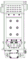
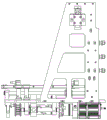
Fig. 1 is a perspective view of a body breaking bracket module;
fig. 2 is a bottom view of a body breaking bracket module;
fig. 3 is a rear view of a body breaking bracket module;
fig. 4 is a plan view of a body breaking bracket module;
fig. 5 is a right side view of the body breaking bracket module;
fig. 6 is a left side view of the body breaking bracket module;
fig. 7 is a front view of a body breaking bracket module;
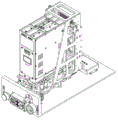
FIG. 8 is a first perspective view of a modular manual-automatic control integrated isolating and breaking device;
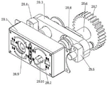
FIG. 9 is a first schematic view of an external manual control lever assembly;
FIG. 10 is a second schematic structural view of an external manual control lever assembly;
FIG. 11 is a third schematic structural view of an external manual control lever assembly;
FIG. 12 is a fourth schematic structural view of an external manual control lever assembly;
FIG. 13 is a fifth schematic structural view of an external manual control lever assembly;
FIG. 14 is a sixth schematic view of an external manual control lever assembly;
fig. 15 is a second perspective view of the modular manual-automatic control integrated isolation breaking device;
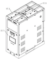
FIG. 16 is a first schematic structural diagram of an appliance control module body;
FIG. 17 is a second schematic structural diagram of an appliance control module body;
FIG. 18 is a third schematic structural diagram of an appliance control module body;
FIG. 19 is a fourth schematic structural diagram of the appliance control module body;
in the figure: 1. the device comprises a base 2, a driving motor 3, a mounting vertical plate A4, a mounting vertical plate B5, a manual adjusting meshing gear 6, a screw nut 7, a screw 8, a sliding optical axis A9, a plug-in tailstock 10, a front support plate 11, a sliding optical axis B12, a sliding sleeve 13, an upper support plate 14, an electrical appliance control module body connecting seat 15, an edge guide rail 16, a guide wheel device 17, an electrical appliance control module body 17.1, an electrical appliance control module box 17.2, a permanent magnet vacuum circuit breaker 17.3, a lifting handle 17.4, an output conductive copper bar plug 17.5, an electric leakage detection device 17.6, a permanent magnet device 17.7, a protector 18, a main body breaking bracket module 19, an operation control electric box 20, an external manual control operating rod assembly 20.1, a manual automatic interchanging switch 20.2, a manual adjusting switch 20.3, a sliding frame 20.4, a sliding rod A20., The device comprises a sliding rod B20.6, a gear shaft 20.7, a gear 20.8, a bearing seat 20.9, a poke rod 20.10, a rotating rod 20.11 and a mounting fixing plate.
Detailed Description
The invention is further described below with reference to the accompanying drawings:
the present invention is further illustrated by the following specific examples, which are not intended to limit the scope of the invention, and any modifications, equivalents, improvements, etc. made within the spirit and principle of the present invention should be included in the scope of the present invention.
Example one
As shown in 16-19, an electrical control module body, includes electrical control module box 17.1, install permanent magnetism vacuum circuit breaker 17.2 in the electrical control module box 17.1, handle 17.3 has on the roof of electrical control module box 17.1, the curb plate is for dismantling the curb plate about electrical control module box 17.1, have output conductive copper bar plug 17.4 on the backplate of electrical control module box 17.1, and output conductive copper bar 17.4 is connected with the inside permanent magnetism vacuum circuit breaker 17.2 of electrical control module box 17.1.
In this embodiment, the bottom of the electrical control module box 17.1 is provided with a positioning hole, and the electrical control module box 17.1 is also internally provided with a leakage detection device 17.5, a permanent magnet device 17.6 and a protector 17.7.
Example two
As shown in fig. 1-15, the modularized manual-automatic integrated isolating and separating device comprises an electric appliance control module body 17 and a main body separating bracket module 18, wherein the electric appliance control module body 17 is mounted on the main body separating bracket module 18, the main body separating bracket module 18 comprises a base 1, the front end of the lower surface of the base 1 is provided with a mounting vertical plate A3 and a mounting vertical plate B4 which are parallel to each other, the rear end of the lower surface of the base 1 is provided with a driving motor 2, two sliding optical axes A8 which are parallel to each other are arranged between the mounting vertical plate A3 and the mounting vertical plate B4, a lead screw 7 is arranged between the two sliding optical axes A8, the front end of the lead screw 7 is rotatably connected with the mounting vertical plate A3, the end of the lead screw passes through the mounting vertical plate A3 to be connected with a manual adjustment meshing gear 5, the tail end of the lead screw 7 is rotatably connected with the mounting vertical plate B4, and, threaded connection has screw nut 6 on lead screw 7, screw nut 6's both ends slide respectively and set up on the slip optical axis A8 that corresponds, the upper surface of base 1 has the layer board device that is used for supporting the electrical apparatus control module body, and the layer board device can slide for base 1, the afterbody of base 1 has opposite plug tailstock 9, screw nut 6 and layer board device fixed connection.
In this embodiment, the supporting plate device includes a front supporting plate 10 installed at the front end of the upper surface of the base 1 and two parallel sliding optical axes B11, the front end of the sliding optical axis B11 is fixed on the front supporting plate 10, the tail end of the sliding optical axis B11 is fixed at the bottom of the opposite-insertion tailstock 9, a sliding sleeve 12 is slidably arranged on each sliding optical axis B11, the sliding sleeve 12 is fixed at the tail of the lower surface of the upper supporting plate 13, an electrical control module body connecting seat 14 for fixing an electrical control module body is arranged on the upper surface of the upper supporting plate 13, and the screw nut 6 is fixedly connected with the sliding sleeve 12 or the upper supporting plate 13 through a connecting rod; edge guide rails 15 are further arranged on two sides of the upper supporting plate 13, the cross section of each edge guide rail 15 is circular and is arranged along the length direction of the upper supporting plate 13, guide wheel devices 16 matched with the edge guide rails 15 are respectively arranged at two ends of the front end of the upper supporting plate 13, and the guide wheel devices 16 are fixedly arranged on the upper surface of the base 1; two sides of the opposite-inserting tailstock 9 are also provided with side guard plates; the middle part of the base 1 is provided with a long hole for a connecting rod to pass through so as to avoid interference; the plug-in tailstock 9 is provided with a plurality of contact letter connectors which are matched with the plug on the electric appliance control module body; the front end of the upper supporting plate 13 is provided with a handle; the connecting base 14 of the electric appliance control module body is provided with a positioning pin which is matched with a positioning hole on the electric appliance control module body.
The working principle of the invention is as follows: a feed switch, an internal circuit breaker, a current transformer, an electrical component such as a power transformer and the like are integrated on an electrical control module body 17, a driving motor 2 rotates forwards, the driving motor 2 drives a lead screw 7 to rotate, the lead screw 7 drives a lead screw nut 6 to slide forwards on a sliding optical axis A8, the sliding lead screw nut 6 drives an upper supporting plate 13 to move forwards relative to a base 1, the electrical control module body 17 is installed on the upper supporting plate 13 through an electrical control module body connecting seat 14, the separation of the electrical control module body 17 from an opposite insertion tailstock 9 is realized, the driving motor 2 rotates backwards, the driving motor 2 drives the lead screw 7 to rotate, the lead screw 7 drives the lead screw nut 6 to slide backwards on a sliding optical axis A8, the sliding lead screw nut 6 drives the upper supporting plate 13 to move backwards relative to the base 1, the electrical control module body 17 is installed on the upper supporting plate 13, the connection between the electrical control module body 17 and the opposite plug-in tailstock 9 is realized, and the operation is more stable under the matching of the sliding optical axis B11 and the sliding sleeve 12 and the matching of the edge guide rail 15 and the guide wheel device 16.
In addition, an output gear of the modularized manual-automatic integrated isolation and breaking device 20 can be meshed with a manual adjusting meshing gear 5 to drive the electric control body and the main body breaking bracket to move relatively, and manual connection or disconnection between the plug-in tailstock 9 and the electric appliance control module body 17 is achieved.
The second embodiment is different from the first embodiment in that the second embodiment further includes an external manual control operation lever assembly, the operation control electrical box is located on one side of the main body breaking bracket module, the electrical appliance control module body, the main body breaking bracket module and the operation control electrical box are all installed inside the explosion-proof housing, the external manual control operation lever assembly is installed outside the explosion-proof housing, the operation control electrical box is electrically connected with the driving motor, the external manual control operation lever assembly 20 includes an explosion-proof housing 20.11, and a manual-automatic interchanging switch 20.1 and a manual adjusting switch 20.2 which are installed outside the explosion-proof housing 20.11, and further includes a sliding frame 20 installed on the other side of the explosion-proof housing 20.11, two ends of the sliding frame 20.3 are respectively slidably arranged on a sliding rod a20.4 and a sliding rod B20.5, inner ends of the sliding rod a20.4 and the sliding rod B20.5 are fixed on an inner side surface of the explosion-proof housing 20.11, a bearing seat 20.8 is installed at one end of the sliding, the gear shaft 20.6 is rotatably mounted on the sliding frame 20.3 through a bearing seat 20.8, one end of the gear shaft 20.6 is provided with a gear 20.7, the other end of the gear shaft 20.6 is provided with a jack, the manual adjusting switch 20.2 is rotatably provided with a rotating rod 20.10, the inner end of the rotating rod 20.10 penetrates through the explosion-proof housing 20.11 and the sliding frame 20.3 to be inserted into the jack at the end part of the gear shaft 20.6 to be in transmission connection with the gear shaft 20.6, the manual and automatic change-over switch 20.1 is used for driving the sliding frame 20.3 to be close to or far away from the explosion-proof housing 20.11, so that the rotating rod 20.10 is inserted into or pulled out of the jack, and the combination or disconnection action of the gear shaft 20.
In this embodiment, the manual-automatic alternation switch 10.1 and the manual adjustment switch 20.2 are integrally arranged; the manual-automatic interchanging switch 20.1 is provided with a jack, a poking rod 20.9 is inserted into the jack, one end of the poking rod 20.9 is in sliding fit with the jack, and the external end of the poking rod 20.9 is pressed or pulled by external force so as to realize the relative telescopic action of the poking rod 20.9 relative to the manual-automatic interchanging switch 20.1; the manual-automatic interchanging switch 20.1 is provided with a poking rod 20.9, one end of the poking rod 20.9 is rotatably connected with the manual-automatic interchanging switch 20.1, the inner end of the poking rod 20.9 is provided with a threaded section, the sliding frame 20.3 is provided with a threaded sleeve connected with the threaded section, and the poking rod 20.9 is controlled to rotate to further realize the relative telescopic action of the poking rod 20.9 relative to the threaded sleeve; the section of the insertion end of the rotating rod 20.10 is non-circular, in particular polygonal; the inner wall of the installation fixing plate 20.11 is also provided with a shifting piece for limiting the rotation of the rotating rod 20.10, and the outer wall of the installation fixing plate 20.11 is provided with a door lock and an unlocking switch for driving the shifting piece to lift so as to realize the unlocking and locking of the rotating rod 20.10.
The working principle of the invention is as follows: manual and automatic switching: the manual-automatic interchanging switch 20.1 is used for driving the sliding frame 20.3 to be close to or far from the mounting fixing plate 20.11, so that the rotating rod 20.10 is inserted into or pulled out of the insertion hole, and the gear shaft 20.6 is combined with or disconnected from the rotating rod 20.10.
Isolating manual and automatic operation: the gear shaft 20.6 is combined with the rotating rod 20.10, the rotating rod 20.10 is manually controlled to be screwed, the driving gear 20.7 is driven to rotate, and the gear 20.7 is used as driving power and matched with a driven wheel on the main body breaking bracket to drive the electric control body and the main body breaking bracket to move relatively to realize connection; the gear shaft 20.6 is disconnected with the rotating rod 20.10, and the main body breaking bracket is provided with a motor to drive the electric control body and the main body breaking bracket to move relatively to realize connection;
the interlocking structure functions are as follows: the inner wall of the installation fixing plate is also provided with a shifting piece for limiting the rotation of the rotating rod, and the outer wall of the installation fixing plate is provided with a door lock and an unlocking switch for driving the shifting piece to ascend and descend so as to realize unlocking and locking of the rotating rod.
The foregoing shows and describes the general principles, essential features, and advantages of the invention. It will be understood by those skilled in the art that the present invention is not limited to the embodiments described above, which are described in the specification and illustrated only to illustrate the principle of the present invention, but that various changes and modifications may be made therein without departing from the spirit and scope of the present invention, which fall within the scope of the invention as claimed. The scope of the invention is defined by the appended claims and equivalents thereof.