CN112255091A - Hardness meter tray for detecting thin steel plate and detection method thereof - Google Patents
Hardness meter tray for detecting thin steel plate and detection method thereof Download PDFInfo
- Publication number
- CN112255091A CN112255091A CN202010916381.3A CN202010916381A CN112255091A CN 112255091 A CN112255091 A CN 112255091A CN 202010916381 A CN202010916381 A CN 202010916381A CN 112255091 A CN112255091 A CN 112255091A
- Authority
- CN
- China
- Prior art keywords
- detection
- supporting circular
- supporting
- truncated cone
- circular truncated
- Prior art date
- Legal status (The legal status is an assumption and is not a legal conclusion. Google has not performed a legal analysis and makes no representation as to the accuracy of the status listed.)
- Granted
Links
- 238000001514 detection method Methods 0.000 title claims abstract description 87
- 229910000831 Steel Inorganic materials 0.000 title claims abstract description 18
- 239000010959 steel Substances 0.000 title claims abstract description 18
- 210000000078 claw Anatomy 0.000 claims abstract description 35
- 239000000463 material Substances 0.000 claims abstract description 26
- 238000012360 testing method Methods 0.000 claims description 12
- 238000009434 installation Methods 0.000 claims description 5
- 238000000034 method Methods 0.000 claims description 4
- 238000005452 bending Methods 0.000 abstract description 5
- 229910000975 Carbon steel Inorganic materials 0.000 description 1
- 230000004075 alteration Effects 0.000 description 1
- 239000010962 carbon steel Substances 0.000 description 1
- 230000006835 compression Effects 0.000 description 1
- 238000007906 compression Methods 0.000 description 1
- 238000010586 diagram Methods 0.000 description 1
- 238000012986 modification Methods 0.000 description 1
- 230000004048 modification Effects 0.000 description 1
- 238000010791 quenching Methods 0.000 description 1
- 230000000171 quenching effect Effects 0.000 description 1
- 239000000126 substance Substances 0.000 description 1
- 238000005496 tempering Methods 0.000 description 1
Images




Classifications
-
- G—PHYSICS
- G01—MEASURING; TESTING
- G01N—INVESTIGATING OR ANALYSING MATERIALS BY DETERMINING THEIR CHEMICAL OR PHYSICAL PROPERTIES
- G01N3/00—Investigating strength properties of solid materials by application of mechanical stress
- G01N3/02—Details
- G01N3/04—Chucks
-
- G—PHYSICS
- G01—MEASURING; TESTING
- G01N—INVESTIGATING OR ANALYSING MATERIALS BY DETERMINING THEIR CHEMICAL OR PHYSICAL PROPERTIES
- G01N3/00—Investigating strength properties of solid materials by application of mechanical stress
- G01N3/40—Investigating hardness or rebound hardness
-
- G—PHYSICS
- G01—MEASURING; TESTING
- G01N—INVESTIGATING OR ANALYSING MATERIALS BY DETERMINING THEIR CHEMICAL OR PHYSICAL PROPERTIES
- G01N2203/00—Investigating strength properties of solid materials by application of mechanical stress
- G01N2203/0014—Type of force applied
- G01N2203/0016—Tensile or compressive
- G01N2203/0019—Compressive
-
- G—PHYSICS
- G01—MEASURING; TESTING
- G01N—INVESTIGATING OR ANALYSING MATERIALS BY DETERMINING THEIR CHEMICAL OR PHYSICAL PROPERTIES
- G01N2203/00—Investigating strength properties of solid materials by application of mechanical stress
- G01N2203/02—Details not specific for a particular testing method
- G01N2203/026—Specifications of the specimen
- G01N2203/0262—Shape of the specimen
- G01N2203/0278—Thin specimens
- G01N2203/0282—Two dimensional, e.g. tapes, webs, sheets, strips, disks or membranes
Landscapes
- Physics & Mathematics (AREA)
- Health & Medical Sciences (AREA)
- Life Sciences & Earth Sciences (AREA)
- Chemical & Material Sciences (AREA)
- Analytical Chemistry (AREA)
- Biochemistry (AREA)
- General Health & Medical Sciences (AREA)
- General Physics & Mathematics (AREA)
- Immunology (AREA)
- Pathology (AREA)
- Investigating Strength Of Materials By Application Of Mechanical Stress (AREA)
Abstract
The invention provides a sclerometer tray for detecting a thin steel plate and a detection method thereof, and the sclerometer tray comprises a supporting circular table, wherein a working boss is arranged above the supporting circular table, the diameter of the working boss is smaller than that of the supporting circular table, a mounting base is arranged below the supporting circular table, the mounting base is arranged on a lifting column of a table type hardness machine, a plurality of movably adjustable reverse-pulling fixing claws are arranged on the periphery of the supporting circular table, a detection sample is arranged on the working boss, clamping claws of the reverse-pulling fixing claws abut against the upper surface of the detection sample, the contact area between a detected object and the supporting circular table is greatly reduced, the supporting force is concentrated due to the reduction of the supporting area of the working boss when a thin material is detected, the material is not subjected to bending deformation, so that the influence is eliminated, the accuracy of detecting the thin material by using.
Description
Technical Field
The invention relates to the field of hardness detection of thin steel plates, in particular to a hardness tester tray for detecting thin steel plates and a detection method thereof.
Background
Hardness is the ability of a material to resist a harder object pressed into its surface, and a hardness test is one of the most important indexes for detecting the material performance, and is also the fastest and most economical method for detecting the mechanical properties, because the hardness test can reflect the differences of the material in chemical components, tissue structures and processing techniques, the hardness test is often used as a supervision means in various industries. When desk-top sclerometer detected the object, partly cover the testee and detect on supporting platform again, present general hardness support round platform all is the T style of calligraphy, the supporting platform diameter of higher authority is all great, supporting platform can give the testee a holding power when the testee is pushed down to the pressure head, the influence of this holding power to the pressure head can be eliminated to the stress that the testee reached certain thickness object itself when the conventionality was detected, when self stress was not enough to eliminate the holding power when material thickness was too thin, slight bending and then influence the data that the pressure head reacted can take place for the material, so lead to detecting data inaccurate, especially the data that detect at thin steel sheet (0.8 mm-2 mm) can all be inaccurate.
Disclosure of Invention
The invention mainly aims to provide a sclerometer tray for detecting a thin steel plate and a detection method thereof, and solves the problem that when the self stress is insufficient to eliminate the supporting force when the thickness of a material is too thin, the material can be slightly bent to influence the data of a pressure head reaction, so that the detection data is inaccurate.
In order to solve the technical problems, the technical scheme adopted by the invention is as follows: a hardometer tray for detecting a thin steel plate and a detection method thereof comprise a supporting circular table, wherein a working boss is arranged above the supporting circular table, the diameter of the working boss is smaller than that of the supporting circular table, an installation base is arranged below the supporting circular table, the installation base is arranged on a lifting column of a table type hardness machine, and a plurality of movably adjustable reverse-pulling fixing claws are arranged on the periphery of the supporting circular table;
the work boss is used for placing the testing sample, and during the use, the jack catch that a plurality of anti-stationary dog that draw leans on testing sample upper surface.
In the preferred scheme, evenly be equipped with a plurality of draw-in grooves of "T" shape structure including supporting round platform periphery, the stationary dog is established inside the draw-in groove to the contrary drawing.
In the preferred scheme, the reverse-pulling fixing claw comprises a vertical plate, a transversely bent claw is arranged at the upper end of the vertical plate, a locking structure is arranged on the claw, and the lower end of the vertical plate is connected with a shaft.
In the preferred scheme, the vertical plate and the shaft are arranged in the clamping groove and can rotate or/and slide in the clamping groove.
In the preferred scheme, the locking structure on the claw is as follows: the clamping jaw is provided with a locking nut, a pressing plate is arranged below the clamping jaw, the locking nut penetrates through the clamping jaw to be rotatably connected with the pressing plate, and the locking nut is in threaded connection with the clamping jaw;
the pressure plate is used for abutting against the upper end face of the detection sample.
In the preferred scheme, the working boss is clamped with the supporting circular truncated cone, or is in threaded connection with the supporting circular truncated cone or is welded with the supporting circular truncated cone.
In the preferred scheme, an anti-rotation structure is arranged between the mounting base below the supporting circular truncated cone and the lifting column.
In the preferred scheme, the anti-rotation structure is a plurality of anti-rotation keys, and the anti-rotation keys are arranged inside the key grooves between the mounting base and the lifting columns.
The detection method comprises the following steps:
s1, installing a plurality of anti-rotation keys in a lifting column of the table type hardness machine, inserting a supporting circular table into the lifting column and preventing rotation through the anti-rotation keys;
s2, mounting a working boss on the surface of the supporting circular truncated cone;
s3, placing the detection sample to be detected on the working boss, adjusting the lifting handle to lift the lifting column, so that the detection sample is close to the detection head and is abutted against the detection head until the pointer of the hardness tester slightly deflects;
s4, rotating the shell of the hardness tester to enable the pointer to point to 0 scale;
s5, pressing down the detection handle, making the detection head rebound after being pressed down, and when detecting the thin material, the support force is concentrated due to the change of the support area of the working boss, which is not enough to cause the material to bend and deform;
and S6, displaying the hardness value of the thin detection sample by a hardness meter.
Detecting a circular detection sample by the following detection method:
a1, the steps of mounting and adjusting the supporting circular truncated cone are the same as the steps S1-S2;
a2, placing a detection sample to be detected on a working boss;
a3, clamping a reverse-pull fixing claw in a clamping groove on the periphery of a supporting circular table, and rotatably adjusting a pressing plate of the reverse-pull fixing claw to abut against the upper surface of a detection sample to be detected through a locking nut to position the position of the detection sample;
a4, adjusting the lifting handle to lift the lifting column, so that the detection sample is close to the detection head and is abutted against the detection head until the pointer of the hardometer slightly moves;
a5, pressing down a detection handle, enabling a detection head to rebound after being pressed down, and when a thin material is detected, the supporting force is concentrated due to the fact that the supporting area of a working boss changes and is insufficient for bending and deforming the material;
a6 hardness scale shows the hardness value of the thin test sample.
The invention provides a sclerometer tray for detecting a thin steel plate and a detection method thereof, wherein the lower end of the sclerometer tray is provided with a mounting base which is connected and mounted with a sclerometer, the middle part of the sclerometer tray is provided with a supporting circular table, and a small-sized working boss is arranged on the supporting circular table.
Drawings
The invention is further illustrated by the following examples in conjunction with the accompanying drawings:
FIG. 1 is a general block diagram of a table hardness machine of the present invention;
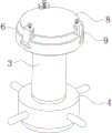
FIG. 2 is a side view of the mounting position of the supporting circular table of the present invention;
FIG. 3 is a front view of the mounting structure of the supporting circular table of the present invention;
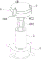
FIG. 4 is a cross-sectional view of the support platform of the present invention;
FIG. 5 is a disassembled structure view of the supporting circular table and the lifting column of the present invention;
FIG. 6 is a disassembled view of the support platform of the present invention;
in the figure: a desktop hardness machine 1; detecting the handle 2; a lifting column 3; a lifting handle 4; a detection head 5; a supporting circular table 6; a working boss 601; a mounting base 602; anti-rotation keys 603; a card slot 604; hardness table 7; detecting the sample 8; reversely pulling the fixed claw 9; a lock nut 901; a compression plate 902; a shaft 903; vertical plate 904.
Detailed Description
Example 1
As shown in fig. 1 to 6, the durometer pallet for detecting the thin steel plate and the detection method thereof include a supporting circular table 6, a working boss 601 is arranged above the supporting circular table 6, the diameter of the working boss 601 is smaller than that of the supporting circular table 6, a mounting base 602 is arranged below the supporting circular table 6, the mounting base 602 is arranged on a lifting column 3 of a table type hardness tester 1, a plurality of movable and adjustable reverse-pulling fixing claws 9 are arranged on the periphery of the supporting circular table 6, the working boss 601 is used for placing a detection sample 8, and when the durometer pallet is used, claws of the reverse-pulling fixing claws 9 abut against the upper surface of the detection sample 8. According to the structure, the supporting circular truncated cone 6, the working boss 601 and the mounting base 602 form the meter tray, the contact area between the detected sample 8 for hardness detection and the supporting circular truncated cone 6 is greatly reduced, the supporting area of the working boss 601 is changed and measured when a thin material is detected, so that the supporting force is not concentrated enough to enable the material to be bent and deformed, the influence is eliminated, the accuracy of detecting the thin material by using a table-type sclerometer is improved, the adaptability is strong, and the meter tray is suitable for popularization and use.
In order to prevent that the thin steel plate from appearing bending deformation's the condition in the detection, adopt the jack catch that reversely draws stationary dog 9 to pull detection sample 8 reverse, prevent that 8 circumferences of detection sample from taking place bending deformation, this structure adapts to circular detection sample 8, mainly uses on the detection of saw disc, carries out effectual detection to the hardness of saw disc, support 6 both ends of round platform connect work boss 601 and installation base 602 respectively, form via the high-quality carbon steel material processing after quenching and tempering, the diameter of work boss 601 about 10mm, support its diameter of round platform 6 and be far greater than the diameter of work boss.
The detection handle 2 controls the lifting column 3 to ascend to the position of the detection head 5, the distance between the detection head 5 and the detection sample 8 is adjusted, the detection handle 2 is pressed down, the adjustment detection head 5 presses the detection sample 8, and the hardness meter 7 displays the hardness value.
In the preferred scheme, a plurality of clamping grooves 604 with inverted T-shaped structures are uniformly arranged on the circumference of the supporting round platform 6, and the reverse-pull fixing claws 9 are arranged inside the clamping grooves 604. With this configuration, as shown in fig. 6, the reverse-pull holding claws 9 can slide in the slots 604 to adjust the distance between the plurality of reverse-pull holding claws 9, and the reverse-pull holding claws 9 can be rotated to remove the test sample 8.
In the preferred scheme, the reverse-pull fixing claw 9 comprises a vertical plate 904, a transversely bent claw is arranged at the upper end of the vertical plate 904, a locking structure is arranged on the claw, and the lower end of the vertical plate 904 is connected with a shaft 903. With this structure, as shown in fig. 6, the vertical plate 904 is connected to the pawl at the upper side and to the shaft 903 at the lower side.
In a preferred embodiment, the vertical plate 904 and the shaft 903 are disposed in the slot 604 and can rotate or/and slide in the slot 604. By the structure, the distance between the multiple reverse-pulling fixing claws 9 can be adjusted, detection samples 8 with different diameters can be detected, and the reverse-pulling fixing claws 9 can be detached conveniently in a rotating mode after the detection is finished.
In the preferred scheme, the locking structure on the claw is as follows: the clamping jaw is provided with a locking nut 901, a pressing plate 902 is arranged below the clamping jaw, the locking nut 901 penetrates through the clamping jaw to be rotatably connected with the pressing plate 902, the locking nut 901 is in threaded connection with the clamping jaw, and the pressing plate 902 is used for abutting against the upper end face of the detection sample 8. With the structure, the locking nut 901 rotates to enable the pressing plate 902 to abut against the upper end face of the detection sample 8, so that the detection samples 8 with different thicknesses can be conveniently detected.
In the preferred scheme, the working boss 601 is clamped with the supporting circular truncated cone 6, or is in threaded connection with the supporting circular truncated cone 6, or is welded with the supporting circular truncated cone 6. From this structure, the structure as an organic whole is welded with support round platform 6 to the preferred work boss 601 of this scheme, perhaps directly adopts the lathe car to come out, joint, perhaps threaded connection, mainly conveniently changes different work bosses 601.
In the preferred scheme, an anti-rotation structure is arranged between the mounting base 602 below the supporting circular truncated cone 6 and the lifting column 3. With this structure, the supporting circular truncated cone 6 is prevented from rotating during detection.
In a preferred embodiment, the rotation-preventing structure is a plurality of rotation-preventing keys 603, and the rotation-preventing keys 603 are disposed inside the key slot between the mounting base 602 and the lifting column 3. With the structure, a commonly used anti-rotation structure is used.
Example 2
As further described with reference to embodiment 1, as shown in fig. 1 to 6, a plurality of rotation preventing keys 603 are installed inside the lifting column 3 of the table hardness tester 1, and the supporting circular truncated cone 6 is inserted into the lifting column 3 and is prevented from rotating by the plurality of rotation preventing keys 603.
The surface of the supporting circular truncated cone 6 is provided with a working boss 601.
The detection sample 8 to be detected is placed on the working boss 601, the lifting handle 4 is adjusted to enable the lifting column 3 to ascend, the detection sample 8 is enabled to be close to the detection head 5 and to abut against the detection head 5 until the pointer of the hardness tester 7 slightly moves.
Rotating the housing of the hardness meter 7 causes the pointer to point to the 0 scale.
The detection handle 2 is pressed down, the detection head 5 rebounds after being pressed down, and the supporting force is concentrated due to the fact that the supporting area of the working boss 601 changes and is not large enough to enable the material to bend and deform when the thin material is detected.
Hardness table 7 shows the hardness values of the thin test sample 8.
Example 3
Further described with reference to embodiments 1 and 2, as shown in fig. 1 to 6, the steps of mounting and adjusting the supporting circular truncated cone 6 are the same as the steps S1 to S2.
The test specimen 8 to be tested is placed on the working platform 601.
The clamping groove 604 on the circumference of the supporting circular truncated cone 6 is clamped into the reverse-pull fixing claw 9, the pressing plate 902 of the reverse-pull fixing claw 9 is rotatably adjusted to abut against the upper surface of the detection sample 8 to be detected through the locking nut 901, and the position of the detection sample 8 is positioned.
The lifting handle 4 is adjusted to enable the lifting column 3 to ascend, so that the detection sample 8 is close to the detection head 5 and is abutted against the detection head 5 until the pointer of the hardness tester 7 slightly moves.
The detection handle 2 is pressed down, the detection head 5 rebounds after being pressed down, and the supporting force is concentrated due to the fact that the supporting area of the working boss 601 changes and is not large enough to enable the material to bend and deform when the thin material is detected.
Hardness table 7 shows the hardness values of the thin test sample 8.
The above-described embodiments are merely preferred embodiments of the present invention, and should not be construed as limiting the present invention, and the scope of the present invention is defined by the claims, and equivalents including technical features described in the claims. I.e., equivalent alterations and modifications within the scope hereof, are also intended to be within the scope of the invention.
Claims (10)
1. The utility model provides a detect sclerometer tray of slim steel sheet which characterized by: the device comprises a supporting circular truncated cone (6), wherein a working boss (601) is arranged above the supporting circular truncated cone (6), the diameter of the working boss (601) is smaller than that of the supporting circular truncated cone (6), an installation base (602) is arranged below the supporting circular truncated cone (6), the installation base (602) is arranged on a lifting column (3) of a table type hardness machine (1), and a plurality of movably adjustable reverse-pulling fixing claws (9) are arranged on the periphery of the supporting circular truncated cone (6);
the working boss (601) is used for placing a detection sample (8), and when the working boss is used, the clamping jaws of the plurality of reverse-pull fixed claws (9) abut against the upper surface of the detection sample (8).
2. The durometer tray for inspecting thin steel plates as claimed in claim 1, wherein: the supporting circular truncated cone comprises a supporting circular truncated cone (6), wherein a plurality of clamping grooves (604) with inverted T-shaped structures are uniformly formed in the periphery of the supporting circular truncated cone, and a reverse-pull fixing claw (9) is arranged in each clamping groove (604).
3. The durometer tray for inspecting thin steel plates as claimed in claim 1, wherein: the reverse-pull fixing claw (9) comprises a vertical plate (904), a transversely bent claw is arranged at the upper end of the vertical plate (904), a locking structure is arranged on the claw, and the lower end of the vertical plate (904) is connected with a shaft (903).
4. The durometer tray of claim 3, wherein: the vertical plate (904) and the shaft (903) are arranged in the clamping groove (604) and can rotate or/and slide in the clamping groove (604).
5. The durometer tray of claim 3, wherein: the locking structure on the claw is as follows: the clamping jaw is provided with a locking nut (901), a pressing plate (902) is arranged below the clamping jaw, the locking nut (901) penetrates through the clamping jaw to be rotatably connected with the pressing plate (902), and the locking nut (901) is in threaded connection with the clamping jaw;
the pressure plate (902) is used for abutting against the upper end face of the detection sample (8).
6. The durometer tray for inspecting thin steel plates as claimed in claim 1, wherein: the working boss (601) is clamped with the supporting circular truncated cone (6), or is in threaded connection or welded.
7. The durometer tray for inspecting thin steel plates as claimed in claim 1, wherein: an anti-rotation structure is arranged between the mounting base (602) below the supporting round platform (6) and the lifting column (3).
8. The durometer tray of claim 7, wherein: the anti-rotation structure is a plurality of anti-rotation keys (603), and the anti-rotation keys (603) are arranged inside a key groove between the mounting base (602) and the lifting column (3).
9. The method of inspecting a durometer tray for a thin steel plate according to any one of claims 1 to 8, wherein: the detection method comprises the following steps:
s1, installing a plurality of anti-rotation keys (603) in a lifting column (3) of a table type hardness machine (1), inserting a supporting circular truncated cone (6) into the lifting column (3) and preventing rotation through the plurality of anti-rotation keys (603);
s2, installing a working boss (601) on the surface of the supporting circular truncated cone (6);
s3, placing a detection sample (8) to be detected on the working boss (601), adjusting the lifting handle (4) to lift the lifting column (3), so that the detection sample (8) is close to the detection head (5) and abuts against the detection head (5) until the pointer of the hardness tester (7) slightly moves;
s4, rotating the shell of the hardometer (7) to enable the pointer to point to 0 scale;
s5, pressing the detection handle (2), enabling the detection head (5) to rebound after being pressed down, and when detecting the thin material, the supporting force is concentrated due to the fact that the supporting area of the working boss (601) changes and is insufficient for enabling the material to bend and deform;
s6, a hardness table (7) shows the hardness value of the thin detection sample (8).
10. The method of inspecting a durometer tray for a thin steel plate according to any one of claims 1 to 8, wherein: detecting a circular test sample (8);
the detection method comprises the following steps:
a1, the steps of mounting and adjusting the supporting circular truncated cone (6) are the same as the steps S1-S2;
a2, placing a detection sample (8) to be detected on a working boss (601);
a3, clamping a reverse-pull fixing claw (9) in a clamping groove (604) on the periphery of a supporting circular truncated cone (6), and rotatably adjusting a pressing plate (902) of the reverse-pull fixing claw (9) to abut against the upper surface of a detection sample (8) to be detected through a locking nut (901) to position the position of the detection sample (8);
a4, adjusting a lifting handle (4) to lift a lifting column (3) to enable a detection sample (8) to be close to a detection head (5) and abut against the detection head (5) until a pointer of a hardness tester (7) slightly deflects;
a5, pressing down a detection handle (2), enabling a detection head (5) to rebound after being pressed down, and when a thin material is detected, the supporting force is concentrated due to the fact that the supporting area of a working boss (601) changes and is insufficient for the material to bend and deform;
a6, hardness table (7) shows the hardness value of the thin test sample (8).
Priority Applications (1)
| Application Number | Priority Date | Filing Date | Title |
|---|---|---|---|
| CN202010916381.3A CN112255091B (en) | 2020-09-03 | 2020-09-03 | Hardness meter tray for detecting thin steel plate and detection method thereof |
Applications Claiming Priority (1)
| Application Number | Priority Date | Filing Date | Title |
|---|---|---|---|
| CN202010916381.3A CN112255091B (en) | 2020-09-03 | 2020-09-03 | Hardness meter tray for detecting thin steel plate and detection method thereof |
Publications (2)
| Publication Number | Publication Date |
|---|---|
| CN112255091A true CN112255091A (en) | 2021-01-22 |
| CN112255091B CN112255091B (en) | 2022-03-29 |
Family
ID=74224848
Family Applications (1)
| Application Number | Title | Priority Date | Filing Date |
|---|---|---|---|
| CN202010916381.3A Active CN112255091B (en) | 2020-09-03 | 2020-09-03 | Hardness meter tray for detecting thin steel plate and detection method thereof |
Country Status (1)
| Country | Link |
|---|---|
| CN (1) | CN112255091B (en) |
Cited By (1)
| Publication number | Priority date | Publication date | Assignee | Title |
|---|---|---|---|---|
| CN114112752A (en) * | 2021-11-30 | 2022-03-01 | 四川海英电子科技有限公司 | Hardness testing device and method for intelligent printed board of automobile |
Citations (6)
| Publication number | Priority date | Publication date | Assignee | Title |
|---|---|---|---|---|
| CN1556386A (en) * | 2004-01-06 | 2004-12-22 | 武汉大学 | Fully digital Vickers hardness tester with convertible scale for test results |
| CN205593867U (en) * | 2016-03-28 | 2016-09-21 | 昆山福尔瑞精密模具有限公司 | Hardness detector |
| CN207502330U (en) * | 2017-12-08 | 2018-06-15 | 重庆柳开机械铸造有限公司 | One kind is used to examine scleroscopic mechanics properties testing instrument |
| CN109540660A (en) * | 2019-01-14 | 2019-03-29 | 南昌航空大学 | Adjustable hardness test fixture |
| CN111220490A (en) * | 2018-11-26 | 2020-06-02 | 青海大学 | Method for testing hardness of metal sheet sample |
| CN213148534U (en) * | 2020-08-10 | 2021-05-07 | 黑旋风锯业股份有限公司 | Hardness detector tray |
-
2020
- 2020-09-03 CN CN202010916381.3A patent/CN112255091B/en active Active
Patent Citations (6)
| Publication number | Priority date | Publication date | Assignee | Title |
|---|---|---|---|---|
| CN1556386A (en) * | 2004-01-06 | 2004-12-22 | 武汉大学 | Fully digital Vickers hardness tester with convertible scale for test results |
| CN205593867U (en) * | 2016-03-28 | 2016-09-21 | 昆山福尔瑞精密模具有限公司 | Hardness detector |
| CN207502330U (en) * | 2017-12-08 | 2018-06-15 | 重庆柳开机械铸造有限公司 | One kind is used to examine scleroscopic mechanics properties testing instrument |
| CN111220490A (en) * | 2018-11-26 | 2020-06-02 | 青海大学 | Method for testing hardness of metal sheet sample |
| CN109540660A (en) * | 2019-01-14 | 2019-03-29 | 南昌航空大学 | Adjustable hardness test fixture |
| CN213148534U (en) * | 2020-08-10 | 2021-05-07 | 黑旋风锯业股份有限公司 | Hardness detector tray |
Cited By (1)
| Publication number | Priority date | Publication date | Assignee | Title |
|---|---|---|---|---|
| CN114112752A (en) * | 2021-11-30 | 2022-03-01 | 四川海英电子科技有限公司 | Hardness testing device and method for intelligent printed board of automobile |
Also Published As
| Publication number | Publication date |
|---|---|
| CN112255091B (en) | 2022-03-29 |
Similar Documents
| Publication | Publication Date | Title |
|---|---|---|
| CN202533335U (en) | Multi-head creep testing device for miniature samples | |
| CN102519803B (en) | Multi-head miniature test specimen creep experiment device and test method | |
| CN104897481B (en) | Bending detection device and detection method | |
| CN102159933B (en) | Continuous or instrumented indentation device with convex bearing surface and use thereof, particularly for metal sheet indentation | |
| CN111323311A (en) | Uniaxial compression deformation detection device and method and system applying same | |
| CN112255091B (en) | Hardness meter tray for detecting thin steel plate and detection method thereof | |
| CN109556971B (en) | Cold spraying sample bending performance test device capable of directly reading bending angle | |
| CN217561218U (en) | Pipe hardness testing tool | |
| CN213148534U (en) | Hardness detector tray | |
| CN201780235U (en) | Thin metal board bending test device | |
| CN118090494B (en) | Hardness detection device of valve body foundry goods | |
| CN111458063B (en) | U-shaped spring clip elastic force testing system and elastic force testing method | |
| CN209945591U (en) | Elastic sheet elasticity detector | |
| CN113176026A (en) | Device for measuring residual stress by indentation method and using method thereof | |
| CN220188228U (en) | An acrylic plate toughness and compression testing device | |
| CN212859201U (en) | Clamp for detecting medical bone plate forging | |
| CN219015944U (en) | Hardness test equipment | |
| CN113358507B (en) | An integrated calibration device for Rockwell hardness tester and its working method | |
| CN211402002U (en) | Hardness tester convenient for testing cylindrical surface of cylinder | |
| CN211374315U (en) | Special fixture for measuring mechanical property sample of metal plate by indentation method | |
| CN220356845U (en) | Stainless steel fastener intensity detection device | |
| CN219674962U (en) | Rapid detection mechanism for through hole and flatness of thin piece | |
| CN112362469A (en) | Small punch test device | |
| CN218673387U (en) | Pressure gauge hoop cam type detection tool | |
| CN213657769U (en) | Utensil is examined in special use of a steering system uide bushing |
Legal Events
| Date | Code | Title | Description |
|---|---|---|---|
| PB01 | Publication | ||
| PB01 | Publication | ||
| SE01 | Entry into force of request for substantive examination | ||
| SE01 | Entry into force of request for substantive examination | ||
| GR01 | Patent grant | ||
| GR01 | Patent grant |