CN112253845A - A construction method for underground pipeline laying and a pipeline laying device - Google Patents
A construction method for underground pipeline laying and a pipeline laying device Download PDFInfo
- Publication number
- CN112253845A CN112253845A CN202010946626.7A CN202010946626A CN112253845A CN 112253845 A CN112253845 A CN 112253845A CN 202010946626 A CN202010946626 A CN 202010946626A CN 112253845 A CN112253845 A CN 112253845A
- Authority
- CN
- China
- Prior art keywords
- pipe
- connecting rod
- section
- top plate
- fixing plate
- Prior art date
- Legal status (The legal status is an assumption and is not a legal conclusion. Google has not performed a legal analysis and makes no representation as to the accuracy of the status listed.)
- Granted
Links
Images



Classifications
-
- F—MECHANICAL ENGINEERING; LIGHTING; HEATING; WEAPONS; BLASTING
- F16—ENGINEERING ELEMENTS AND UNITS; GENERAL MEASURES FOR PRODUCING AND MAINTAINING EFFECTIVE FUNCTIONING OF MACHINES OR INSTALLATIONS; THERMAL INSULATION IN GENERAL
- F16L—PIPES; JOINTS OR FITTINGS FOR PIPES; SUPPORTS FOR PIPES, CABLES OR PROTECTIVE TUBING; MEANS FOR THERMAL INSULATION IN GENERAL
- F16L1/00—Laying or reclaiming pipes; Repairing or joining pipes on or under water
- F16L1/024—Laying or reclaiming pipes on land, e.g. above the ground
- F16L1/028—Laying or reclaiming pipes on land, e.g. above the ground in the ground
- F16L1/036—Laying or reclaiming pipes on land, e.g. above the ground in the ground the pipes being composed of sections of short length
Landscapes
- Engineering & Computer Science (AREA)
- General Engineering & Computer Science (AREA)
- Mechanical Engineering (AREA)
- Sewage (AREA)
- Excavating Of Shafts Or Tunnels (AREA)
Abstract
The invention discloses a construction method for laying underground pipelines, which comprises the following steps: pulling the back-expanding head, the pipe connector, the first section of pipe and the fixing plate into a soil body; the fixed plate is disassembled, and the pulling device pushes the pull rod reversely, or the pulling device pushes the pull rod reversely firstly and then disassembles the fixed plate; mounting a second section of pipe on the rear side of the first section of pipe, and arranging a fixing plate on the rear side of the second section of pipe; the traction device pulls the back expanding head and tightly presses and sleeves the first section of pipe and the second section of pipe, then the traction device pulls the back expanding head, the first section of pipe and the second section of pipe into the soil body, and the steps are repeated until all the pipes are pulled into the soil body.
Description
[ technical field ] A method for producing a semiconductor device
The invention relates to the field of buildings, in particular to a construction method for laying underground pipelines, and also relates to a pipeline laying device.
[ background of the invention ]
As shown in fig. 1, in the trenchless underground pipeline laying construction, a first working well 6 and a second working well 7 are respectively excavated on the ground at two ends of a specified route, a traction device 3 is arranged near the first working well 6, a pipeline laying device 1 is arranged in the second working well 7, the tail part of the pipeline laying device 1 is used for fixing a pipe 5, the pipeline laying device 1 is pulled by the traction device 3 through a pull rod 4 to reach the first working well 6 along the set route, meanwhile, a plurality of pipes 5 are sequentially arranged at the tail part of the pipeline laying device 1 in the second working well 7 end to end, and when the pipeline laying device 1 is pulled into the first working well 6, the pipes 5 are just laid on the specified route.
A section of matching section which is mutually sleeved is arranged between every two adjacent pipes 5, when one pipe 5 is installed, a jacking device is needed to press the pipe 5 which is installed later to the pipe 5 which is installed earlier so that the pipe 5 and the pipe 5 are mutually sleeved, then the pipe 5 is fixed, then the pipeline laying device provided with the pipe 5 is pulled forwards through the traction device 3 until all the pipes 5 are pulled into the channel 2 to be repaired, and finally the steps are sequentially repeated until the whole channel 2 to be repaired is laid. The traditional construction method needs to arrange a jacking device capable of jacking the pipe 5, fixedly install the jacking device and remove the jacking device after the construction is finished, so that the whole construction process has the disadvantages of multiple steps, low construction efficiency, multiple working procedures, large occupied space and large workload of constructors.
[ summary of the invention ]
The invention aims to overcome the defects of the prior art, provides a construction method for laying underground pipelines, has the advantages of concise steps in the whole construction process, improvement on construction efficiency, small occupied space and small workload of constructors by using the construction method, and also provides a pipeline laying device for implementing the construction method.
The invention is realized by the following technical scheme:
a construction method for underground pipe laying, comprising the steps of:
A. the back expansion head is arranged in a second working well, and the pulling device pulls the back expansion head into a soil body through a pull rod;
B. arranging a pipe adapter at the rear side of the back expansion head and sleeving the pipe adapter on the connecting rod in a sliding manner;
C. installing a first section of pipe on the pipe adapter, arranging a fixing plate at the rear side of the first section of pipe, and clamping and fixing the first section of pipe by the fixing plate and the pipe adapter;
D. the traction device pulls the back expansion head and pulls the first section of the pipe into the soil body;
E. the fixed plate is disassembled, the pulling device pushes the pull rod reversely, or the pulling device pushes the pull rod reversely first and then the fixed plate is disassembled;
F. mounting a second section of pipe on the rear side of the first section of pipe, and arranging a fixing plate on the rear side of the second section of pipe;
G. the traction device pulls the back-expanding head and tightly presses and sleeves the first section of pipe and the second section of pipe, and then the traction device pulls the back-expanding head, the first section of pipe and the second section of pipe into a soil body;
H. and repeating the steps E-G until all the pipes are drawn into the soil body.
According to the construction method, the top plate is arranged on the traction device and at the rear side of the pipe adaptor, and the top plate is arranged on the connecting rod and can abut against the rear part of the pipe adaptor when the connecting rod moves forwards.
According to the construction method, the connecting rod is formed by splicing a plurality of connecting rod monomers end to end.
The invention also provides a pipeline laying device, which comprises a back-expanding head used for connecting the traction device, wherein the back side of the back-expanding head is connected with a connecting rod, the back side of the back-expanding head is provided with a pipe adapter used for connecting pipes, the pipe adapter is sleeved on the connecting rod and can slide back and forth on the connecting rod, the back side of the pipe adapter is provided with a fixing plate which can press the pipes to the pipe adapter so as to clamp and fix the pipes, the back side of the pipe adapter and the connecting rod is provided with a top plate, the top plate abuts against the back part of the pipe adapter when the connecting rod moves forwards, a gap L1 is reserved between the back-expanding head and the pipe adapter, and the gap L1 is greater than or equal to the length L2 of the sleeving parts of the two pipes.
According to the pipe laying device, the pipe adapter is rotatably connected to the connecting rod, and the top plate is rotatably connected to the connecting rod.
In the pipe laying device, the pipe adaptor is provided with the abutting part which protrudes to the rear side and abuts against the top plate when the top plate moves forwards.
According to the pipeline laying device, the bearing is arranged in the middle of the top plate, the bearing outer ring is connected with the top plate, and the bearing inner ring is connected with the connecting rod in an interference fit manner.
In the pipe-laying apparatus, the bearing is a thrust bearing.
According to the pipeline laying device, the pipe adapter is provided with the slurry inlet communicated with the inner cavity of the pipe, the fixing plate is provided with the slurry outlet communicated with the inner cavity of the pipe, and the connecting rod and the spiral blade are arranged between the pipe adapter and the fixing plate.
Compared with the prior art, the invention has the following advantages:
1. the construction method can tightly press and sleeve two adjacent pipes without additionally arranging jacking equipment for pushing the pipes, thereby improving the construction efficiency, occupying small space and having small workload of constructors.
2. In the step G of the construction method, only the traction device is required to pull the fixing plate, then the traction device keeps the traction action until the pipe is pulled to the soil body, and in the traditional construction method, the jacking equipment for pushing the pipe needs to be installed in the step, and the jacking equipment is detached after the pipe is sleeved, so that the construction method is more convenient and fast compared with the traditional construction method.
3. The top plate is arranged on the connecting rod and can abut against the rear part of the pipe adapter when the connecting rod moves forwards, so that the pipe is prevented from being damaged due to pressure generated between the fixing plate and the pipe adapter.
[ description of the drawings ]
FIG. 1 is a first schematic illustration of the construction process of the present invention;
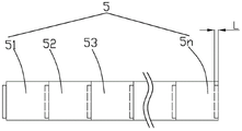
FIG. 2 is a front view of the tubing of the present invention;
FIG. 3 is a second schematic illustration of the construction process of the present invention;
FIG. 4 is a third schematic illustration of the construction process of the present invention;
FIG. 5 is a fourth schematic illustration of the construction process of the present invention;
FIG. 6 is a cross-sectional view of the pipe laying apparatus of the present invention;
FIG. 7 is a partial cross-sectional view of the pipe laying apparatus of the present invention.
[ detailed description ] embodiments
The invention is further described below with reference to the accompanying drawings:
as shown in fig. 1 to 6, a construction method for underground pipe laying, comprising the steps of:
A. the back expansion head 11 is arranged in the second working well 7, the pulling device 3 pulls the back expansion head 11 to the soil body through the pull rod 4, and the back expansion head 11 is jacked in the soil body and excavates a channel so that the subsequent pipe 5 can enter.
B. The pipe adapter 12 is arranged at the rear side of the back expansion head 11 and is sleeved on the connecting rod 14 in a sliding manner.
C. The first tube 51 is mounted on the tube adapter 12, the fixing plate 13 is disposed behind the first tube 51, the fixing plate 13 and the tube adapter 12 clamp and fix the first tube 51, and as an embodiment, the fixing plate 13 is mounted and fixed on the connecting rod 14, so as to compress the tube 5.
D. The pulling device 3 pulls the back-reaming head 11 and pulls the first tube length 51 into the soil mass.
E. The fixed plate 13 is disassembled, the pulling device 3 reversely pushes the pull rod 4, the pull rod 4 pushes the back expansion head 11 to move backwards, the back expansion head 11 drives the connecting rod 14 to move backwards, and the moving distance of the two is determined by a gap L1 between the pipe material connector 12 and the back expansion head 11.
F. A second joint member 52 is attached to the rear side of the first joint member 51, and the fixing plate 13 is disposed on the rear side of the second joint member 52.
G. The pulling device 3 pulls the back-reaming head 11 and tightly sleeves the first pipe section 51 and the second pipe section 52, and then the pulling device 3 pulls the back-reaming head 11, the first pipe section 51 and the second pipe section 52 into the soil body.
H. The steps of E-G are repeated until all the pipes 5 are drawn into the soil.
By using the construction method, two adjacent pipes 5 can be compressed and sleeved on the premise of not additionally arranging a jacking device for pushing the pipes to be sleeved, so that the complex steps of installing and disassembling the jacking device and manually operating the jacking device are omitted, the construction efficiency is improved, the occupied space is small, and the workload of constructors is small.
Preferably, as shown in fig. 6 and 7, the pulling device 3 is provided with a top plate 15 at the rear side of the tube adaptor 12, the top plate 15 is provided on the connecting rod 14 and can abut against the rear part of the tube adaptor 12 when the connecting rod 14 moves forwards, when the connecting rod 14 moves backwards, the tube adaptor 12 is not moved, and when the connecting rod 14 moves forwards, the tube adaptor 12 can be driven to move forwards, so as to prevent the tube 5 from being squeezed and damaged when the fixing plate 13 moves forwards.
In step B, a gap L1 may be left between the tube adaptor 12 and the back-expansion head 11, or the back-expansion head 11 and the pull rod 4 may slide a certain distance by a sliding connection structure. Preferably, the gap L1 between the tube adaptor 12 and the back-reaming head 11 is the same as the length L2 of the sleeved portion of the two adjacent tubes 5, so that when the connecting rod 14 moves backwards until the back-reaming head 11 abuts against the tube adaptor 12, the connecting rod 14 moves by just the length L of the sleeved portion of the two adjacent tubes 5, and only the fixing plate 13 needs to be mounted against the second tube 52, and after the second tube 52 is sleeved with the first tube 51, the top plate 15 abuts against the back of the tube adaptor 12. If the gap L1 between the pipe adaptor 12 and the back-expansion head 11 is not consistent with the length L2 of the sleeved part of two adjacent pipes 5, the moving distance of the connecting rod 14 needs to be calculated during construction to calculate the installation position of the fixing plate 13.
Preferably, as shown in fig. 6, the connecting rod 14 is formed by splicing a plurality of connecting rod single bodies 141 end to end, so that the connecting rod single bodies 141 can be continuously installed in the second working well 7, and the space required by installation is saved.
As shown in fig. 6 and 7, the present invention further provides a pipe laying device, comprising a back-expanding head 11 for connecting a pulling device 3, a connecting rod 14 connected to the back side of the back-expanding head 11, a pipe adapter 12 arranged at the back side of the back-expanding head 11 for connecting a pipe 5, the pipe adapter 12 being sleeved on the connecting rod 14 and capable of sliding back and forth on the connecting rod 14, a fixing plate 13 arranged at the back side of the pipe adapter 12 and capable of pressing the pipe 5 towards the pipe adapter 12 to clamp and fix the pipe 5, a top plate 15 arranged on the connecting rod 14 and at the back side of the pipe adapter 12, the top plate 15 abutting against the back of the pipe adapter 12 when the connecting rod 14 moves forward, because the pipe adapter 12 is slidably sleeved on the connecting rod 14, the connecting rod 14 can move backward relative to the pipe adapter 12, after a second section of the pipe 5 is installed and the fixing plate 13 is reinstalled, connecting rod 14 moves forward, and connecting rod 14 moves forward just drives roof 15 and supports and lean on tubular product adapter 12 and promote the tubular product adapter and move forward, prevents to produce pressure between fixed plate 13 and the tubular product adapter 12, and such pipe laying device can be applied to foretell construction method to reach the effect that the construction is convenient, the efficiency of construction is high.
Since the pulling device 3 is usually driven by the pull rod 4 to rotate and move the back-reaming head 11 around the axis in the actual construction process, as shown in fig. 6 and 7, the tube adapter 12 is rotatably connected to the connecting rod 14, the top plate 15 is rotatably connected to the connecting rod 14, and more specifically, the tube adapter 12 is slidably sleeved on the connecting rod 14, the top plate 15 is connected with the connecting rod 14 in an interference fit manner through a bearing 151, and the bearing 151 is preferably a thrust bearing, so that the forehead plate 15 can rotate relative to the connecting rod 14 without affecting the connecting rod 14 to drive the top plate 15 to move axially.
Preferably, as shown in fig. 6 and 7, the pipe adaptor 12 is provided with a slurry inlet 121 communicated with an inner cavity 500 of the pipe 5, the fixing plate 13 is provided with a slurry outlet 131 communicated with the inner cavity 500 of the pipe 5, and the connecting rod 14 is provided with a helical blade 16 between the pipe adaptor 12 and the fixing plate 13, so that when the connecting rod 14 rotates, the helical blade 16 can be driven to rotate, and as long as the rotating direction is set, a part of soil mass in the inner cavity 500 of the pipe 5 can be effectively pushed backwards, and finally the soil mass is discharged from the slurry outlet 131.
In addition, in the steps a to C, since the actual construction may be limited by factors such as environment, equipment and personnel, the pipe adaptor 12 in the step B and the first section of pipe 51 in the step C may be installed and connected with the fixing plate 13 in the construction, and then the step a is completed, so that the sequence of installing the parts is substantially different.
The foregoing is merely an example of the present invention and common general knowledge of known specific structures and features of the embodiments is not described herein in any greater detail. It should be noted that, for those skilled in the art, without departing from the structure of the present invention, several changes and modifications can be made, which should also be regarded as the protection scope of the present invention, and these will not affect the effect of the implementation of the present invention and the practical applicability of the invention. The scope of the claims of the present application shall be determined by the contents of the claims, and the description of the embodiments and the like in the specification shall be used to explain the contents of the claims.
Claims (10)
1. A construction method for underground pipeline laying is characterized in that: the method comprises the following steps:
A. the back expansion head (11) is arranged in a second working well (7), and the back expansion head (11) is pulled into soil by the pulling device (3) through the pull rod (4);
B. arranging a pipe adapter (12) at the rear side of the back expansion head (11) and sleeving a connecting rod (14) in a sliding manner;
C. a first pipe (51) is arranged on the pipe connector (12), a fixing plate (13) is arranged on the rear side of the first pipe (51), and the fixing plate (13) and the pipe connector (12) clamp and fix the first pipe (51);
D. the traction device (3) pulls the back expansion head (11) and pulls the first pipe (51) into the soil body;
E. the fixed plate (13) is disassembled, the pulling device (3) reversely pushes the pull rod (4), or the pulling device (3) reversely pushes the pull rod (4) firstly and then the fixed plate (13) is disassembled;
F. a second pipe section (52) is arranged on the rear side of the first pipe section (51), and the fixing plate (13) is arranged on the rear side of the second pipe section (52);
G. the pulling device (3) pulls the back expansion head (11) and tightly sleeves the first pipe section (51) and the second pipe section (52), and then the pulling device (3) pulls the back expansion head (11), the first pipe section (51) and the second pipe section (52) into a soil body;
H. and repeating the steps E-G until all the pipes (5) are drawn into the soil body.
2. The construction method according to claim 1, characterized in that: the pipe connector is characterized in that a top plate (15) is arranged on the traction device (3) and on the rear side of the pipe connector (12), the top plate (15) is arranged on the connecting rod (14) and can abut against the rear part of the pipe connector (12) when the connecting rod (14) moves forwards.
3. The construction method according to claim 1, characterized in that: the connecting rod (14) is formed by splicing a plurality of connecting rod monomers (141) end to end.
4. A pipe laying apparatus characterized by: the pipe connecting device comprises a back-expanding head (11) used for connecting a traction device (3), wherein the back side of the back-expanding head (11) is connected with a connecting rod (14), a pipe connector (12) used for connecting a pipe (5) is arranged on the back side of the back-expanding head (11), the pipe connector (12) is sleeved on the connecting rod (14) and can slide back and forth on the connecting rod (14), a fixing plate (13) capable of pressing the pipe (5) to the pipe connector (12) to clamp the pipe (5) is arranged on the back side of the pipe connector (12), a top plate (15) is arranged on the connecting rod (14) and on the back side of the pipe connector (12), and the top plate (15) abuts against the back part of the pipe connector (12) when the connecting rod (14) moves forwards.
5. The pipe laying device according to claim 4, wherein: the pipe connector (12) is rotatably connected to the connecting rod (14), and the top plate (15) is rotatably connected to the connecting rod (14).
6. The pipe laying device according to claim 4, wherein: the pipe adaptor (12) is provided with an abutting part (122) which protrudes towards the rear side and abuts against the top plate (15) when the top plate (15) moves forwards.
7. The pipe laying device of claim 5, wherein: the middle part of the top plate (15) is provided with a bearing (151), the outer ring of the bearing (151) is connected with the top plate (15), and the inner ring of the bearing (151) is connected with the connecting rod (14) in an interference fit manner.
8. The pipe laying device of claim 7, wherein: the bearing (151) is a thrust bearing.
9. The pipe laying device of claim 5, wherein: a gap L1 is reserved between the back expansion head (11) and the pipe adaptor (12), and the gap L1 is larger than or equal to the length L2 of the sleeving parts of the two pipes (5).
10. The pipe laying device of claim 5, wherein: the pipe adapter (12) is provided with a slurry inlet (121) communicated with an inner cavity (500) of the pipe (5), the fixing plate (13) is provided with a slurry discharge port (131) communicated with the inner cavity (500) of the pipe (5), and the connecting rod (14) is provided with a helical blade (16) between the pipe adapter (12) and the fixing plate (13).
Priority Applications (1)
| Application Number | Priority Date | Filing Date | Title |
|---|---|---|---|
| CN202010946626.7A CN112253845B (en) | 2020-09-10 | 2020-09-10 | A construction method for laying underground pipelines and a pipeline laying device |
Applications Claiming Priority (1)
| Application Number | Priority Date | Filing Date | Title |
|---|---|---|---|
| CN202010946626.7A CN112253845B (en) | 2020-09-10 | 2020-09-10 | A construction method for laying underground pipelines and a pipeline laying device |
Publications (2)
| Publication Number | Publication Date |
|---|---|
| CN112253845A true CN112253845A (en) | 2021-01-22 |
| CN112253845B CN112253845B (en) | 2025-03-11 |
Family
ID=74231571
Family Applications (1)
| Application Number | Title | Priority Date | Filing Date |
|---|---|---|---|
| CN202010946626.7A Active CN112253845B (en) | 2020-09-10 | 2020-09-10 | A construction method for laying underground pipelines and a pipeline laying device |
Country Status (1)
| Country | Link |
|---|---|
| CN (1) | CN112253845B (en) |
Cited By (1)
| Publication number | Priority date | Publication date | Assignee | Title |
|---|---|---|---|---|
| CN114294472A (en) * | 2022-01-12 | 2022-04-08 | 深圳市骏鹏润实业有限公司 | Water supply and drainage engineering pipeline laying equipment and method thereof |
Citations (3)
| Publication number | Priority date | Publication date | Assignee | Title |
|---|---|---|---|---|
| US6305880B1 (en) * | 1997-01-09 | 2001-10-23 | Wrb Company, Inc. | Device and method for trenchless replacement of underground pipe |
| CN108194758A (en) * | 2018-02-27 | 2018-06-22 | 广东管博管道技术科技有限公司 | A kind of pipeline is quiet to draw fragmentation to repair structure |
| CN212745307U (en) * | 2020-09-10 | 2021-03-19 | 广东智慧碧管管道技术科技有限公司 | Pipeline laying device |
-
2020
- 2020-09-10 CN CN202010946626.7A patent/CN112253845B/en active Active
Patent Citations (3)
| Publication number | Priority date | Publication date | Assignee | Title |
|---|---|---|---|---|
| US6305880B1 (en) * | 1997-01-09 | 2001-10-23 | Wrb Company, Inc. | Device and method for trenchless replacement of underground pipe |
| CN108194758A (en) * | 2018-02-27 | 2018-06-22 | 广东管博管道技术科技有限公司 | A kind of pipeline is quiet to draw fragmentation to repair structure |
| CN212745307U (en) * | 2020-09-10 | 2021-03-19 | 广东智慧碧管管道技术科技有限公司 | Pipeline laying device |
Cited By (1)
| Publication number | Priority date | Publication date | Assignee | Title |
|---|---|---|---|---|
| CN114294472A (en) * | 2022-01-12 | 2022-04-08 | 深圳市骏鹏润实业有限公司 | Water supply and drainage engineering pipeline laying equipment and method thereof |
Also Published As
| Publication number | Publication date |
|---|---|
| CN112253845B (en) | 2025-03-11 |
Similar Documents
| Publication | Publication Date | Title |
|---|---|---|
| CN103181043B (en) | Lay the method that multiple continuous print cable section connects with the cable forming long length | |
| CN212745307U (en) | Pipeline laying device | |
| AU622675B2 (en) | Device for the in situ repair of a pipe | |
| CN112253845B (en) | A construction method for laying underground pipelines and a pipeline laying device | |
| CN217760995U (en) | High-efficient type muddy water balance push pipe construction equipment | |
| KR102499153B1 (en) | Pneumatic underground pipeline penetration and continuity tester | |
| CN108953759A (en) | Self-balancing is two-way to eat pipe replacement restorative procedure and device | |
| CN220323598U (en) | Pipeline front shaper for optical cable air blowing | |
| CN209762517U (en) | Building pipeline reinforcing structure | |
| CN220216094U (en) | Pipeline plastic repair equipment | |
| JP2002369326A (en) | Pipe laying pressure feed head and pipe laying method using the same | |
| KR20050093749A (en) | The method of dual excavating for a tunnel and its apparatus | |
| CN119340725A (en) | A tensile waterproof explosion-proof cable connector | |
| CN117345275A (en) | A shield tunnel segment stratum grouting reinforcement device | |
| JP2004316810A (en) | Earthquake-proof tube propulsion construction method and propulsive force transmission device | |
| CN223374947U (en) | Coupling | |
| JPS6151715B2 (en) | ||
| CN217630348U (en) | Town road pipeline quick assembly disassembly structure | |
| CN222437382U (en) | A mechanical guide device for trenchless underground pipeline repair | |
| CN224218105U (en) | Split type cable joint | |
| CN218914186U (en) | A pipeline repair and reinforcement device and its repair and reinforcement structure | |
| US7374368B2 (en) | Method and apparatus for slip-lining | |
| CN219432725U (en) | Pipeline connecting piece of quick connection pipeline | |
| CN220337733U (en) | Pipeline connector for pipeline transformation | |
| CN211276263U (en) | Internal expansion and external contraction buckling device |
Legal Events
| Date | Code | Title | Description |
|---|---|---|---|
| PB01 | Publication | ||
| PB01 | Publication | ||
| SE01 | Entry into force of request for substantive examination | ||
| SE01 | Entry into force of request for substantive examination | ||
| GR01 | Patent grant | ||
| GR01 | Patent grant | ||
| TR01 | Transfer of patent right | ||
| TR01 | Transfer of patent right |
Effective date of registration: 20260413 Address after: 621700 Sichuan Province Mianyang City Jiangyou City Dongxing Town Xin Su Village Group 6 No. 14 Patentee after: He Wenwen Country or region after: China Address before: 523000 Guangdong Province Dongguan City Houti Town Kangle North Road No. 31 Patentee before: Guangdong smart Bi Pipe Technology Co.,Ltd. Country or region before: China |