CN112242594A - Battery and device - Google Patents
Battery and device Download PDFInfo
- Publication number
- CN112242594A CN112242594A CN202011507137.8A CN202011507137A CN112242594A CN 112242594 A CN112242594 A CN 112242594A CN 202011507137 A CN202011507137 A CN 202011507137A CN 112242594 A CN112242594 A CN 112242594A
- Authority
- CN
- China
- Prior art keywords
- battery
- battery cell
- electrode
- case
- conductive member
- Prior art date
- Legal status (The legal status is an assumption and is not a legal conclusion. Google has not performed a legal analysis and makes no representation as to the accuracy of the status listed.)
- Granted
Links
Images


Classifications
-
- H—ELECTRICITY
- H01—ELECTRIC ELEMENTS
- H01M—PROCESSES OR MEANS, e.g. BATTERIES, FOR THE DIRECT CONVERSION OF CHEMICAL ENERGY INTO ELECTRICAL ENERGY
- H01M10/00—Secondary cells; Manufacture thereof
- H01M10/42—Methods or arrangements for servicing or maintenance of secondary cells or secondary half-cells
- H01M10/48—Accumulators combined with arrangements for measuring, testing or indicating the condition of cells, e.g. the level or density of the electrolyte
- H01M10/482—Accumulators combined with arrangements for measuring, testing or indicating the condition of cells, e.g. the level or density of the electrolyte for several batteries or cells simultaneously or sequentially
-
- H—ELECTRICITY
- H01—ELECTRIC ELEMENTS
- H01M—PROCESSES OR MEANS, e.g. BATTERIES, FOR THE DIRECT CONVERSION OF CHEMICAL ENERGY INTO ELECTRICAL ENERGY
- H01M10/00—Secondary cells; Manufacture thereof
- H01M10/05—Accumulators with non-aqueous electrolyte
- H01M10/052—Li-accumulators
-
- H—ELECTRICITY
- H01—ELECTRIC ELEMENTS
- H01M—PROCESSES OR MEANS, e.g. BATTERIES, FOR THE DIRECT CONVERSION OF CHEMICAL ENERGY INTO ELECTRICAL ENERGY
- H01M10/00—Secondary cells; Manufacture thereof
- H01M10/05—Accumulators with non-aqueous electrolyte
- H01M10/052—Li-accumulators
- H01M10/0525—Rocking-chair batteries, i.e. batteries with lithium insertion or intercalation in both electrodes; Lithium-ion batteries
-
- H—ELECTRICITY
- H01—ELECTRIC ELEMENTS
- H01M—PROCESSES OR MEANS, e.g. BATTERIES, FOR THE DIRECT CONVERSION OF CHEMICAL ENERGY INTO ELECTRICAL ENERGY
- H01M10/00—Secondary cells; Manufacture thereof
- H01M10/05—Accumulators with non-aqueous electrolyte
- H01M10/054—Accumulators with insertion or intercalation of metals other than lithium, e.g. with magnesium or aluminium
-
- H—ELECTRICITY
- H01—ELECTRIC ELEMENTS
- H01M—PROCESSES OR MEANS, e.g. BATTERIES, FOR THE DIRECT CONVERSION OF CHEMICAL ENERGY INTO ELECTRICAL ENERGY
- H01M10/00—Secondary cells; Manufacture thereof
- H01M10/42—Methods or arrangements for servicing or maintenance of secondary cells or secondary half-cells
- H01M10/425—Structural combination with electronic components, e.g. electronic circuits integrated to the outside of the casing
-
- H—ELECTRICITY
- H01—ELECTRIC ELEMENTS
- H01M—PROCESSES OR MEANS, e.g. BATTERIES, FOR THE DIRECT CONVERSION OF CHEMICAL ENERGY INTO ELECTRICAL ENERGY
- H01M10/00—Secondary cells; Manufacture thereof
- H01M10/42—Methods or arrangements for servicing or maintenance of secondary cells or secondary half-cells
- H01M10/48—Accumulators combined with arrangements for measuring, testing or indicating the condition of cells, e.g. the level or density of the electrolyte
- H01M10/486—Accumulators combined with arrangements for measuring, testing or indicating the condition of cells, e.g. the level or density of the electrolyte for measuring temperature
-
- H—ELECTRICITY
- H01—ELECTRIC ELEMENTS
- H01M—PROCESSES OR MEANS, e.g. BATTERIES, FOR THE DIRECT CONVERSION OF CHEMICAL ENERGY INTO ELECTRICAL ENERGY
- H01M50/00—Constructional details or processes of manufacture of the non-active parts of electrochemical cells other than fuel cells, e.g. hybrid cells
- H01M50/20—Mountings; Secondary casings or frames; Racks, modules or packs; Suspension devices; Shock absorbers; Transport or carrying devices; Holders
- H01M50/204—Racks, modules or packs for multiple batteries or multiple cells
- H01M50/207—Racks, modules or packs for multiple batteries or multiple cells characterised by their shape
- H01M50/209—Racks, modules or packs for multiple batteries or multiple cells characterised by their shape adapted for prismatic or rectangular cells
-
- H—ELECTRICITY
- H01—ELECTRIC ELEMENTS
- H01M—PROCESSES OR MEANS, e.g. BATTERIES, FOR THE DIRECT CONVERSION OF CHEMICAL ENERGY INTO ELECTRICAL ENERGY
- H01M50/00—Constructional details or processes of manufacture of the non-active parts of electrochemical cells other than fuel cells, e.g. hybrid cells
- H01M50/20—Mountings; Secondary casings or frames; Racks, modules or packs; Suspension devices; Shock absorbers; Transport or carrying devices; Holders
- H01M50/298—Mountings; Secondary casings or frames; Racks, modules or packs; Suspension devices; Shock absorbers; Transport or carrying devices; Holders characterised by the wiring of battery packs
-
- H—ELECTRICITY
- H01—ELECTRIC ELEMENTS
- H01M—PROCESSES OR MEANS, e.g. BATTERIES, FOR THE DIRECT CONVERSION OF CHEMICAL ENERGY INTO ELECTRICAL ENERGY
- H01M50/00—Constructional details or processes of manufacture of the non-active parts of electrochemical cells other than fuel cells, e.g. hybrid cells
- H01M50/50—Current conducting connections for cells or batteries
- H01M50/502—Interconnectors for connecting terminals of adjacent batteries; Interconnectors for connecting cells outside a battery casing
- H01M50/503—Interconnectors for connecting terminals of adjacent batteries; Interconnectors for connecting cells outside a battery casing characterised by the shape of the interconnectors
-
- H—ELECTRICITY
- H01—ELECTRIC ELEMENTS
- H01M—PROCESSES OR MEANS, e.g. BATTERIES, FOR THE DIRECT CONVERSION OF CHEMICAL ENERGY INTO ELECTRICAL ENERGY
- H01M50/00—Constructional details or processes of manufacture of the non-active parts of electrochemical cells other than fuel cells, e.g. hybrid cells
- H01M50/50—Current conducting connections for cells or batteries
- H01M50/502—Interconnectors for connecting terminals of adjacent batteries; Interconnectors for connecting cells outside a battery casing
- H01M50/507—Interconnectors for connecting terminals of adjacent batteries; Interconnectors for connecting cells outside a battery casing comprising an arrangement of two or more busbars within a container structure, e.g. busbar modules
-
- H—ELECTRICITY
- H01—ELECTRIC ELEMENTS
- H01M—PROCESSES OR MEANS, e.g. BATTERIES, FOR THE DIRECT CONVERSION OF CHEMICAL ENERGY INTO ELECTRICAL ENERGY
- H01M50/00—Constructional details or processes of manufacture of the non-active parts of electrochemical cells other than fuel cells, e.g. hybrid cells
- H01M50/50—Current conducting connections for cells or batteries
- H01M50/502—Interconnectors for connecting terminals of adjacent batteries; Interconnectors for connecting cells outside a battery casing
- H01M50/509—Interconnectors for connecting terminals of adjacent batteries; Interconnectors for connecting cells outside a battery casing characterised by the type of connection, e.g. mixed connections
- H01M50/51—Connection only in series
-
- H—ELECTRICITY
- H01—ELECTRIC ELEMENTS
- H01M—PROCESSES OR MEANS, e.g. BATTERIES, FOR THE DIRECT CONVERSION OF CHEMICAL ENERGY INTO ELECTRICAL ENERGY
- H01M50/00—Constructional details or processes of manufacture of the non-active parts of electrochemical cells other than fuel cells, e.g. hybrid cells
- H01M50/50—Current conducting connections for cells or batteries
- H01M50/543—Terminals
- H01M50/547—Terminals characterised by the disposition of the terminals on the cells
- H01M50/548—Terminals characterised by the disposition of the terminals on the cells on opposite sides of the cell
-
- H—ELECTRICITY
- H01—ELECTRIC ELEMENTS
- H01M—PROCESSES OR MEANS, e.g. BATTERIES, FOR THE DIRECT CONVERSION OF CHEMICAL ENERGY INTO ELECTRICAL ENERGY
- H01M50/00—Constructional details or processes of manufacture of the non-active parts of electrochemical cells other than fuel cells, e.g. hybrid cells
- H01M50/50—Current conducting connections for cells or batteries
- H01M50/569—Constructional details of current conducting connections for detecting conditions inside cells or batteries, e.g. details of voltage sensing terminals
-
- H—ELECTRICITY
- H01—ELECTRIC ELEMENTS
- H01M—PROCESSES OR MEANS, e.g. BATTERIES, FOR THE DIRECT CONVERSION OF CHEMICAL ENERGY INTO ELECTRICAL ENERGY
- H01M50/00—Constructional details or processes of manufacture of the non-active parts of electrochemical cells other than fuel cells, e.g. hybrid cells
- H01M50/50—Current conducting connections for cells or batteries
- H01M50/572—Means for preventing undesired use or discharge
- H01M50/574—Devices or arrangements for the interruption of current
- H01M50/583—Devices or arrangements for the interruption of current in response to current, e.g. fuses
-
- H—ELECTRICITY
- H01—ELECTRIC ELEMENTS
- H01M—PROCESSES OR MEANS, e.g. BATTERIES, FOR THE DIRECT CONVERSION OF CHEMICAL ENERGY INTO ELECTRICAL ENERGY
- H01M50/00—Constructional details or processes of manufacture of the non-active parts of electrochemical cells other than fuel cells, e.g. hybrid cells
- H01M50/50—Current conducting connections for cells or batteries
- H01M50/572—Means for preventing undesired use or discharge
- H01M50/584—Means for preventing undesired use or discharge for preventing incorrect connections inside or outside the batteries
- H01M50/588—Means for preventing undesired use or discharge for preventing incorrect connections inside or outside the batteries outside the batteries, e.g. incorrect connections of terminals or busbars
-
- G—PHYSICS
- G01—MEASURING; TESTING
- G01R—MEASURING ELECTRIC VARIABLES; MEASURING MAGNETIC VARIABLES
- G01R31/00—Arrangements for testing electric properties; Arrangements for locating electric faults; Arrangements for electrical testing characterised by what is being tested not provided for elsewhere
- G01R31/36—Arrangements for testing, measuring or monitoring the electrical condition of accumulators or electric batteries, e.g. capacity or state of charge [SoC]
- G01R31/382—Arrangements for monitoring battery or accumulator variables, e.g. SoC
-
- G—PHYSICS
- G01—MEASURING; TESTING
- G01R—MEASURING ELECTRIC VARIABLES; MEASURING MAGNETIC VARIABLES
- G01R31/00—Arrangements for testing electric properties; Arrangements for locating electric faults; Arrangements for electrical testing characterised by what is being tested not provided for elsewhere
- G01R31/36—Arrangements for testing, measuring or monitoring the electrical condition of accumulators or electric batteries, e.g. capacity or state of charge [SoC]
- G01R31/396—Acquisition or processing of data for testing or for monitoring individual cells or groups of cells within a battery
-
- H—ELECTRICITY
- H01—ELECTRIC ELEMENTS
- H01M—PROCESSES OR MEANS, e.g. BATTERIES, FOR THE DIRECT CONVERSION OF CHEMICAL ENERGY INTO ELECTRICAL ENERGY
- H01M2200/00—Safety devices for primary or secondary batteries
- H01M2200/10—Temperature sensitive devices
- H01M2200/103—Fuse
-
- H—ELECTRICITY
- H01—ELECTRIC ELEMENTS
- H01M—PROCESSES OR MEANS, e.g. BATTERIES, FOR THE DIRECT CONVERSION OF CHEMICAL ENERGY INTO ELECTRICAL ENERGY
- H01M2220/00—Batteries for particular applications
- H01M2220/20—Batteries in motive systems, e.g. vehicle, ship, plane
-
- H—ELECTRICITY
- H01—ELECTRIC ELEMENTS
- H01M—PROCESSES OR MEANS, e.g. BATTERIES, FOR THE DIRECT CONVERSION OF CHEMICAL ENERGY INTO ELECTRICAL ENERGY
- H01M50/00—Constructional details or processes of manufacture of the non-active parts of electrochemical cells other than fuel cells, e.g. hybrid cells
- H01M50/10—Primary casings, jackets or wrappings of a single cell or a single battery
- H01M50/116—Primary casings, jackets or wrappings of a single cell or a single battery characterised by the material
- H01M50/117—Inorganic material
- H01M50/119—Metals
-
- H—ELECTRICITY
- H01—ELECTRIC ELEMENTS
- H01M—PROCESSES OR MEANS, e.g. BATTERIES, FOR THE DIRECT CONVERSION OF CHEMICAL ENERGY INTO ELECTRICAL ENERGY
- H01M50/00—Constructional details or processes of manufacture of the non-active parts of electrochemical cells other than fuel cells, e.g. hybrid cells
- H01M50/20—Mountings; Secondary casings or frames; Racks, modules or packs; Suspension devices; Shock absorbers; Transport or carrying devices; Holders
- H01M50/249—Mountings; Secondary casings or frames; Racks, modules or packs; Suspension devices; Shock absorbers; Transport or carrying devices; Holders specially adapted for aircraft or vehicles, e.g. cars or trains
-
- Y—GENERAL TAGGING OF NEW TECHNOLOGICAL DEVELOPMENTS; GENERAL TAGGING OF CROSS-SECTIONAL TECHNOLOGIES SPANNING OVER SEVERAL SECTIONS OF THE IPC; TECHNICAL SUBJECTS COVERED BY FORMER USPC CROSS-REFERENCE ART COLLECTIONS [XRACs] AND DIGESTS
- Y02—TECHNOLOGIES OR APPLICATIONS FOR MITIGATION OR ADAPTATION AGAINST CLIMATE CHANGE
- Y02E—REDUCTION OF GREENHOUSE GAS [GHG] EMISSIONS, RELATED TO ENERGY GENERATION, TRANSMISSION OR DISTRIBUTION
- Y02E60/00—Enabling technologies; Technologies with a potential or indirect contribution to GHG emissions mitigation
- Y02E60/10—Energy storage using batteries
Abstract
The embodiment of the invention provides a battery and a device. A battery, comprising: the battery pack comprises at least two battery units, a battery unit and a battery pack, wherein the battery units are provided with a shell and two electrode connecting parts which are arranged on two sides of the shell and have opposite polarities; a conductive member disposed at one side of the case, the conductive member being for electrically connecting one of the two electrode connection parts of the first battery cell and the case of one of the first battery cell and the second battery cell; and a signal detection part disposed at the other side of the case, the signal detection part having a signal detection line for electrically connecting the other of the two electrode connection parts of the first battery cell and the case of one of the first battery cell and the second battery cell. The embodiment of the invention can simplify the wiring mode of the signal detection circuit, improve the reliability of the signal detection circuit and further improve the safety performance of the battery.
Description
Technical Field
The invention relates to the technical field of energy storage equipment, in particular to a battery and a device.
Background
With the increasingly improved technology of electric automobiles, the electric automobiles are closer to the lives of people, and meanwhile, the performance requirements of the electric automobiles on batteries for providing energy are higher and higher.
At present, in order to increase the energy storage capacity of a battery, a plurality of battery cells are generally arranged in the battery, and the plurality of battery cells are arranged in parallel in the battery. In order to ensure the safety of the battery, electrical parameters (such as voltage or temperature) of a plurality of battery units need to be collected and detected, and a signal detection component for collecting and detecting the electrical parameters has the problem of poor reliability caused by complex wiring.
Therefore, a new battery and device are needed.
Disclosure of Invention
The embodiment of the invention provides a battery and a device, aiming at solving the problem of poor reliability caused by complex wiring of a signal detection component in the battery.
An embodiment of the first aspect of the invention provides a battery comprising: the battery pack comprises at least two battery units, a battery unit and a battery pack, wherein the battery units are provided with a shell and two electrode connecting parts which are arranged on two sides of the shell and have opposite polarities; a conductive member disposed at one side of the case, the conductive member being for electrically connecting one of the two electrode connection parts of the first battery cell and the case of one of the first battery cell and the second battery cell; and the signal detection part is arranged on the other side of the shell and is provided with a signal detection circuit, the signal detection circuit is used for electrically connecting the other electrode connecting part of the first battery unit and the shell of one of the first battery unit and the second battery unit, and the signal detection circuit and the conductive part are electrically connected to the shell of the same battery unit, so that the signal detection circuit can form a detection loop with the two electrode connecting parts of the first battery unit through the shell and the conductive part of the same battery unit, and the detection of the temperature or voltage signal of the first battery unit is realized.
According to an embodiment of the first aspect of the present invention, further comprising: a first bus member provided at one side of the case, the first bus member being for electrically connecting electrode connection parts of the first and second battery cells to realize series connection; the conductive member is used to electrically connect the first bus member and the housing.
The first bus bar part is provided to enable the series connection of the first battery cell and the second battery cell, and the first bus bar part has electrical parameters of two electrode connections on one side of the first battery cell and the second battery cell. The conductive part is connected with the first bus part and the shell, the electrical parameter information of the two electrode connecting parts can be transmitted to the other side of the shell through the conductive part and the shell, and the signal detection circuit can detect the temperature or voltage signals of the first battery unit and the second battery unit on the other side of the shell, so that the circuit arrangement of the whole detection circuit is further simplified, and the reliability of the detection circuit is improved.
According to any one of the foregoing embodiments of the first aspect of the present invention, the conductive member is formed by extending outward from one side of the first bus member. That is, the conductive member is integrally formed with the first bus bar member, so that the structures of the conductive member and the first bus bar member can be simplified, and the stability and reliability of the connection between the conductive member and the first bus bar member can be improved.
According to any one of the preceding embodiments of the first aspect of the present invention, the conductive member includes a first pin and a second pin connected to each other, the first pin being for electrically connecting the first bus member, and the second pin being for electrically connecting the housing. This allows the conductive member to be connected to the first bus bar member and the case without interfering with each other, and can simplify the assembly of the battery.
According to any one of the embodiments of the first aspect of the present invention, the first pin and the second pin are separately provided, and the battery further includes a connection member for electrically connecting the first pin and the second pin.
According to any one of the preceding embodiments of the first aspect of the present invention, the connecting member is provided with a first fusing portion for fusing when the current reaches a threshold value to form an open circuit between the first pin and the second pin. This can improve the safety of the battery.
According to any one of the preceding embodiments of the first aspect of the present invention, the two electrode connections comprise a first electrode connection and a second electrode connection, the battery unit further comprises a third battery unit connected in series with the second battery unit, and the first electrode connection and the second electrode connection are alternately arranged in sequence on the same side of the housing; the first bus member is used for connecting a first electrode connection part of the first battery cell and a second electrode connection part of the second battery cell; the battery further comprises a second bus member arranged on the other side of the housing, the second bus member is used for connecting the first electrode connecting part of the second battery unit and the second electrode connecting part of the third battery unit, and the signal detection circuit is used for electrically connecting the second electrode connecting part of the first battery unit, the second bus member and the housing.
On the same side of the housing, the first electrode connecting parts and the second electrode connecting parts are alternately distributed in sequence, so that the first bus member located on one side of the housing and the second bus member located on the other side of the housing can be connected with different electrode connecting parts of different battery units, for example, the first bus member is connected with the first electrode connecting part of the first battery unit and the second electrode connecting part of the second battery unit, the second bus member is connected with the first electrode connecting part of the second battery unit and the second electrode connecting part of the third battery unit, and more than three battery units can be connected in series through the first bus member and the second bus member.
In addition, the first electrode connection part of the first battery cell forms a detection circuit with the second electrode connection part of the first battery cell through the first bus member, the conductive member, the case of the same battery cell, the signal detection line, so that the signal detection member can detect a temperature or voltage signal of the first battery cell.
The second electrode connection part of the second battery unit is connected to the first bus member, the first electrode connection part of the second battery unit is connected to the second bus member, and the second electrode connection part of the second battery unit forms a detection loop through the first bus member, the conductive member, the housing of the same battery unit, the signal detection line, the second bus member, and the first electrode connection part of the second battery unit, so that the signal detection member can detect a temperature or voltage signal of the second battery unit.
According to any one of the preceding embodiments of the first aspect of the present invention, the conductive member is provided with a second fusing portion for fusing when the current reaches a threshold value to break the electrode connecting portion and the housing. This can improve the safety of the battery.
According to any one of the foregoing embodiments of the first aspect of the present invention, the second fusing portion is formed by partial cross-sectional contraction of the conductive member.
In these embodiments, the second fusing part has a small partial cross-section. When the current reaches a threshold value, the second fusing part fuses before other parts of the conductive part. So that the conductive member is broken by the position of the second fusing part and the electrical connection between the electrode connecting part and the case is broken. In addition, the second fusing part is formed by partial section contraction of the conductive component, the structure of the conductive component can be simplified, a fuse does not need to be arranged in the conductive component, the processing molding and the installation of the conductive component are convenient, and the manufacturing and installation cost of the battery is reduced.
According to any one of the embodiments of the first aspect of the present invention, the electrode connecting portion is disposed to protrude from the outer surface of the case in the first direction;
the shell is provided with a first connecting part, the conductive part is provided with a second connecting part, at least one of the first connecting part and the second connecting part extends along a first direction, and the first connecting part and the second connecting part are mutually connected to enable the conductive part to be connected to the shell. The height difference of the electrode connecting part extending out of the outer surface of the shell can be compensated through the first connecting part and/or the second connecting part, so that the connection between the conductive part and the shell is more stable.
According to any one of the embodiments of the first aspect of the present invention, the first connecting portion protrudes from the outer surface of the housing along the first direction;
the second connecting portion is lapped on the surface of the first connecting portion, which is deviated from the shell, or the second connecting portion is arranged around the periphery of the first connecting portion.
Embodiments of the second aspect of the present invention provide an apparatus comprising a battery according to any one of the embodiments of the first aspect, the battery being configured to provide electrical energy.
In a battery provided in an embodiment of the first aspect of the invention, the battery includes a battery cell, a conductive member, and a signal detection member. The battery cell has a case and two electrode connection parts having opposite polarities, the first battery cell and the second battery cell are connected in series with each other, and the conductive member is used to connect one of the electrode connection parts of the first battery cell with the case of one of the first battery cell and the second battery cell, so that the case carries an electric signal of the electrode connection part. The signal detection circuit of the signal detection part is electrically connected with the other electrode connecting part of the first battery unit and the shell, and the signal detection circuit and the conductive part are connected with the same shell. That is, one of the electrode connection parts of the first battery cell located at one side of the case can be connected to the signal detection line through the case and the conductive member, and the signal detection line is also connected to the other electrode connection part of the first battery cell located at the other side of the case. The signal detection line can thus form a detection loop between the conductive member and the two electrode connection portions of the case and the first battery cell, so that the signal detection member can detect a temperature or voltage signal of the first battery cell.
In the embodiment of the invention, the signal detection part is arranged at the other side of the shell, the signal detection circuit can be connected to the two electrode connecting parts positioned at the two sides of the shell in the first battery unit at the same side of the shell, and the signal detection circuit does not need to be arranged across the two sides of the shell. Therefore, the embodiment of the invention can simplify the wiring mode of the signal detection circuit, improve the reliability of the signal detection circuit and further improve the safety performance of the battery.
Drawings
Other features, objects and advantages of the invention will become apparent from the following detailed description of non-limiting embodiments with reference to the accompanying drawings in which like or similar reference characters refer to the same or similar parts.
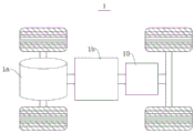
FIG. 1 is a schematic structural diagram of a vehicle according to an embodiment of the present invention;
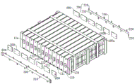
fig. 2 is a schematic structural diagram of a battery provided in an embodiment of the present invention;
fig. 3 is an exploded view of a battery according to an embodiment of the present invention;
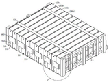
fig. 4 is a schematic structural diagram of a second side of a battery according to an embodiment of the present invention;
fig. 5 is a schematic structural diagram of a battery provided in an embodiment of the invention at another viewing angle;
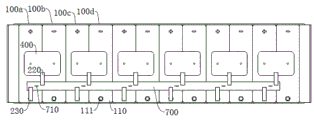
fig. 6 is a schematic structural diagram of a first side of a battery according to an embodiment of the present invention;
fig. 7 is a schematic structural diagram of a battery according to another embodiment of the present invention;
fig. 8 is a schematic view of a first side of a battery according to another embodiment of the present invention;
FIG. 9 is an enlarged partial view of FIG. 7 at I;
fig. 10 is a schematic structural view of a battery according to still another embodiment of the present invention;
fig. 11 is a schematic view of a first side of a battery according to yet another embodiment of the present invention;
FIG. 12 is another embodiment of a schematic view of a portion of the enlarged structure of FIG. 7 at I;
fig. 13 is a partial enlarged schematic view of fig. 7 showing still another embodiment of the structure.
Description of reference numerals:
1. a vehicle; 1a, a motor; 1b, a controller;
10. a battery; 11. a side plate; 12. fixing belts; 13. a battery cell; 13a, an electrode terminal;
100. a battery cell; 100a, a first battery cell; 100b, a second battery cell 100c, a third battery cell; 100d, a fourth battery cell; 110. a housing; 111. a first connection portion; 120. an electrode connecting portion; 121. a first electrode connection portion; 122. a second electrode connection part;
200. a conductive member; 210. a second fusing part; 220. a first pin; 230. a second pin; 240. a second connecting portion;
300. a signal detection section; 310. a signal detection circuit;
400. a first bus member;
500. a second bus member;
600. a third bus member;
700. a connecting member; 710. a first fusing part.
Detailed Description
Features and exemplary embodiments of various aspects of the present invention will be described in detail below. In the following detailed description, numerous specific details are set forth in order to provide a thorough understanding of the present invention. It will be apparent, however, to one skilled in the art that the present invention may be practiced without some of these specific details. The following description of the embodiments is merely intended to provide a better understanding of the present invention by illustrating examples of the present invention. In the drawings and the following description, at least some well-known structures and techniques have not been shown in detail in order to avoid unnecessarily obscuring the present invention; also, the dimensions of some of the structures may be exaggerated for clarity. Furthermore, the described features, structures, or characteristics may be combined in any suitable manner in one or more embodiments.
In the description of the present invention, it is to be noted that, unless otherwise specified, "a plurality" means two or more; the terms "upper," "lower," "left," "right," "inner," "outer," and the like, as used herein, refer to an orientation or positional relationship indicated for convenience in describing the invention and to simplify description, but do not indicate or imply that the referenced device or element must have a particular orientation, be constructed and operated in a particular orientation, and thus should not be construed as limiting the invention. Furthermore, the terms "first," "second," and the like are used for descriptive purposes only and are not to be construed as indicating or implying relative importance.
The directional terms appearing in the following description are intended to be illustrative in all directions, and are not intended to limit the specific construction of embodiments of the present invention. In the description of the present invention, it should also be noted that, unless otherwise explicitly specified or limited, the terms "mounted" and "connected" are to be interpreted broadly, e.g., as either a fixed connection, a removable connection, or an integral connection; can be directly connected or indirectly connected. The specific meaning of the above terms in the present invention can be understood as appropriate to those of ordinary skill in the art.
In the present application, the battery cell may include a lithium ion secondary battery, a lithium ion primary battery, a lithium sulfur battery, a sodium lithium ion battery, a sodium ion battery, a magnesium ion battery, or the like, which is not limited in the embodiments of the present application. The battery cell may be a cylinder, a flat body, a rectangular parallelepiped, or other shapes, which is not limited in the embodiments of the present application. The battery cells are generally divided into three types in an encapsulation manner: the cylindrical battery monomer, the square battery monomer and the soft package battery monomer are not limited in the embodiment of the application.
Reference to a battery in embodiments of the present application refers to a single physical module that includes one or more battery cells to provide higher voltage and capacity. For example, the battery referred to in the present application may include a battery module or a battery pack, etc. Batteries generally include a case for enclosing one or more battery cells. The box can avoid liquid or other foreign matters to influence the charging or discharging of battery monomer.
The battery monomer comprises an electrode assembly and electrolyte, wherein the electrode assembly comprises a positive plate, a negative plate and an isolating membrane. The battery cell mainly depends on metal ions moving between the positive plate and the negative plate to work. The positive plate includes anodal mass flow body and anodal active substance layer, and anodal active substance layer coats in anodal mass flow body's surface, and the mass flow body protrusion in the mass flow body of the anodal active substance layer of coating has not coated, and the mass flow body of the anodal active substance layer of coating is as anodal utmost point ear. Taking a lithium ion battery as an example, the material of the positive electrode current collector may be aluminum, and the positive electrode active material may be lithium cobaltate, lithium iron phosphate, ternary lithium, lithium manganate, or the like. The negative pole piece includes negative current collector and negative pole active substance layer, and the negative pole active substance layer coats in the surface of negative current collector, and the mass flow body protrusion in the mass flow body of coating negative pole active substance layer of uncoated negative pole active substance layer, the mass flow body of uncoated negative pole active substance layer is as negative pole utmost point ear. The material of the negative electrode current collector may be copper, and the negative electrode active material may be carbon, silicon, or the like. In order to ensure that the fuse is not fused when a large current is passed, the number of the positive electrode tabs is multiple and the positive electrode tabs are stacked together, and the number of the negative electrode tabs is multiple and the negative electrode tabs are stacked together. The material of the isolation film can be PP or PE, etc. In addition, the electrode assembly may have a winding structure or a lamination structure, and the embodiment of the present application is not limited thereto. The positive electrode tab and the negative electrode tab of the battery monomer are respectively and electrically connected with two electrode terminals with opposite polarities on the battery monomer so as to output electric energy.
At present, in order to improve the space utilization rate of the battery pack, a plurality of battery cells in the battery pack are generally arranged in a lying manner, that is, electrode terminals of the battery cells are located at two sides of the battery cells in the horizontal direction. The detection circuit for collecting the temperature or voltage signal of the battery cell needs to be connected to two electrode terminals of the battery cell to form a detection loop with the two electrode terminals. When the free electrode terminals of battery are located at the two sides of the battery in the horizontal direction, the detection circuit needs to be arranged at the two sides of the battery, so that the wiring of the detection circuit is complex, the reliability of the detection circuit is reduced, the cost of the detection circuit is high, and the safety performance of the battery is reduced.
The present invention has been made to solve the above-mentioned problems. For a better understanding of the present invention, the battery and the device according to the embodiment of the present invention will be described in detail with reference to fig. 1 to 13.
The embodiment of the first aspect of the present application provides an electric device using a battery as a power source. The electric device can be, but is not limited to, a vehicle, a ship, an aircraft or the like.
The technical scheme described in the embodiment of the application is applicable to various devices using batteries, such as mobile phones, portable devices, notebook computers, battery cars, electric toys, electric tools, electric vehicles, ships, spacecrafts and the like, and the spacecrafts comprise airplanes, rockets, space shuttles, spacecrafts and the like.
It should be understood that the technical solutions described in the embodiments of the present application are not limited to be applied to the above-described devices, but may also be applied to all devices using batteries, and for brevity of description, the following embodiments are all described by taking an electric vehicle as an example.
Referring to fig. 1, one embodiment of the present application provides a vehicle 1. The vehicle 1 may be a fuel automobile, a gas automobile, or a new energy automobile. The new energy automobile can be a pure electric automobile, a hybrid electric automobile or a range-extended automobile and the like.
In an embodiment of the present application, the vehicle 1 may include a motor 1a, a controller 1b, and a battery 10. The controller 1b is used to control the battery 10 to supply power to the motor 1 a. The motor 1a is connected to wheels through a transmission mechanism, thereby driving the vehicle 1 to travel. The battery 10 may serve as a driving power source for the vehicle 1, instead of or in part in place of fuel or natural gas to provide driving power for the vehicle 1.
In one example, the battery 10 may be provided at the bottom or the front or rear of the vehicle 1. The battery 10 may be used to power the vehicle 1. In one example, the battery 10 may be used as an operating power source of the vehicle 1 for a circuit system of the vehicle 1. Alternatively, the battery 10 may be used for operational power requirements for start-up, navigation and operation of the vehicle 1.
Referring to fig. 2 and fig. 3, fig. 2 is a schematic structural diagram of a battery 10 according to an embodiment of the present invention. Fig. 3 is an exploded view of a battery 10 according to an embodiment of the present invention.
According to the battery 10 provided by the embodiment of the present invention, the battery 10 includes: at least two battery cells 100, the battery cells 100 having a case 110 and two electrode connecting parts 120 disposed at both sides of the case 110 and having opposite polarities, the battery cells 100 including a first battery cell 100a and a second battery cell 100b connected in series; a conductive member 200 disposed at one side of the case 110, the conductive member 200 for electrically connecting one of the two electrode connection parts 120 of the first battery cell 100a and the case 110 of one of the first and second battery cells 100a and 100 b; and a signal detection part 300 disposed at the other side of the case 110, the signal detection part 300 having a signal detection line 310, the signal detection line 310 being used to electrically connect the other of the two electrode connection parts 120 of the first battery cell 100a and the case 110 of one of the first battery cell 100a and the second battery cell 100b, and the signal detection line 310 and the conductive member 200 being electrically connected to the case 110 of the same battery cell 100, so that the signal detection line 310 can form a detection loop with the two electrode connection parts 120 of the first battery cell 100a through the case 110 and the conductive member 200 of the same battery cell 100, to realize detection of the temperature or voltage signal of the first battery cell 100 a.
In the battery 10 provided in the embodiment of the first aspect of the invention, the battery 10 includes the battery cell 100, the conductive member 200, and the signal detection member 300. The battery cell 100 has a case 110 and two electrode connections 120 having opposite polarities, the first battery cell 100a and the second battery cell 100b are connected in series with each other, and the conductive member 200 serves to connect one of the electrode connections 120 of the first battery cell 100a with the case 110 of one of the first battery cell 100a and the second battery cell 100b, so that the case 110 carries an electrical signal of the electrode connection 120. The signal detection line 310 of the signal detection member 300 is electrically connected to the other electrode connection part 120 of the first battery cell 100a and the case 110, and the signal detection line 310 and the conductive member 200 are connected to the same case 110. The signal detection part 300 may be a Printed Circuit Board (PCB) or a flexible circuit board (FPC), and the signal detection line 310 may be a metal conductive foil, such as a copper foil or an aluminum foil, disposed on the PCB or the FPC. One of the electrode connecting parts 120 of the first battery cell 100a located at one side of the case 110 can be connected to the signal detection line 310 through the case 110 and the conductive member 200, and the signal detection line 310 is also connected to the other electrode connecting part 120 of the first battery cell 100a located at the other side of the case 110. The signal detection line 310 can form a detection loop between the conductive member 200 and the case 110 and the two electrode connection parts 120 of the first battery cell 100a, so that the signal detection member 300 can detect a temperature or voltage signal of the first battery cell 100 a.
In the embodiment of the present invention, the signal detection part 300 is disposed at the other side of the case 110, the signal detection line 310 may be connected to the two electrode connection parts 120 of the first battery cell 100a at both sides of the case 110 at the same side of the case 110, and the signal detection line 310 does not need to be disposed across both sides of the case 110. Therefore, the embodiment of the present invention can simplify the wiring manner of the signal detection line 310, improve the reliability of the signal detection line 310, and further improve the safety performance of the battery 10.
In addition, in the battery 10 according to the embodiment of the present invention, the case 110 of the battery cell 100 is connected to the electrode connecting portion 120 through the conductive member 200, and thus, compared to the case 110 directly connected to the electrode connecting portion 120 of the battery cell 100, it is possible to improve the safety problem caused by the insulation failure between the electrode connecting portion 120 and the case 110, and to improve the safety performance of the battery 10.
The battery unit 100 may include one battery cell 13. Or the battery unit 100 includes two or more battery cells 13 connected in parallel with each other. When the battery unit 100 includes one battery cell 13, the case 110 of the battery unit 100 is the case 110 of the battery cell 13, and the electrode connection part 120 is the electrode terminal 13a of the battery cell 13. When the battery unit 100 includes two or more battery cells 13 connected in parallel, the case 110 of the battery unit 100 may be the case 110 of any one of the two or more battery cells 13 connected in parallel, the electrode connection part 120 of the battery unit 100 may be the electrode terminal 13a of any one of the battery cells 13, or the electrode connection part 120 of the battery unit 100 may be an electrode terminal group formed of the electrode terminals 13a of the two or more battery cells 13 having the same polarity and connected in parallel.
The embodiment of the present invention takes the battery unit 100 including one battery cell 13 as an example. In this case, the case 110 of the battery unit 100 is the case 110 of the battery cell 13, and the electrode connecting portion 120 of the battery unit 100 is the electrode terminal 13a of the battery cell 13.
When the battery unit 100 includes one battery cell 13, the battery 10 includes at least two battery cells 13, the battery cell 13 has a housing 110 and electrode terminals 13a disposed at both sides of the housing 110 and having opposite polarities, and the battery cell 13 includes a first battery cell and a second battery cell connected in series. The conductive member 200 is used to connect one of the electrode terminals 13a of the first battery cell and the case 110 of one of the first battery cell and the second battery cell, for example, the conductive member 200 is used to connect one of the electrode terminals 13a of the first battery cell and the case 110 of the second battery cell. The signal detection line 310 of the signal detection member 300 is used to connect the other electrode terminal 13a of the first battery cell and the case 110 of the second battery cell.
Accordingly, one of the electrode terminals 13a of the first battery cell forms a detection loop through the conductive member 200, the case 110 of the second battery cell 100b, the signal detection line 310, and the other electrode terminal 13a of the first battery cell, so that the signal detection member 300 can detect a temperature or voltage signal of the first battery cell through the signal detection line 310.
In other embodiments, the conductive member 200 may be further connected to one of the electrode terminals 13a of the first battery cell and the case 110 of the first battery cell, and the signal detection line 310 connects the other electrode terminal 13a of the first battery cell and the case 110 of the first battery cell. The signal detection line 310 forms a detection loop between the conductive member 200 and the case 110 of the first battery cell and the two electrode terminals 13a of the first battery cell, so that the signal detection member 300 can detect a temperature or voltage signal of the first battery cell through the signal detection line 310.
In the embodiment of the present invention, the electrical signal on the electrode terminal 13a located at one side of the case 110 is transmitted to the other side of the case 110 through the conductive member 200 and the case 110, so that the signal detection line 310 can connect the two electrode terminals 13a of the first battery cell at the other side of the case 110. Therefore, the signal detection line 310 does not need to be disposed across the two sides of the case 110, so that the wiring manner of the signal detection line 310 can be simplified, the reliability of the signal detection line 310 can be improved, and the safety performance of the battery 10 can be improved.
The two sides of the housing 110 are, for example, two sides of the housing 110 in the length direction (X direction in fig. 2), the two sides of the housing 110 include a first side and a second side, the conductive member 200 is located at the first side, and the signal detection member 300 is located at the second side. That is, one side of the housing 110 is a first side, and the other side of the housing 110 is a second side.
Referring to fig. 4 to fig. 6, fig. 4 is a schematic structural diagram of a second side of a battery 10 according to an embodiment of the invention. Fig. 5 is a schematic structural diagram of a battery 10 according to another view angle. Fig. 6 is a schematic structural diagram of a first side of a battery 10 according to an embodiment of the present invention.
According to the battery 10 provided by the embodiment of the present invention, the battery 10 further includes: a first bus member 400 provided at a first side of the case 110, the first bus member 400 electrically connecting the electrode connection parts 120 of the first and second battery cells 100a and 100b to realize series connection; the conductive member 200 is used to electrically connect the first bus member 400 and the case 110.
It is understood that the conductive member 200 may be coupled to the case 110 of the first battery cell 100a or the case 110 of the second battery cell 100b in this embodiment, and the case 110 to which the signal detection line 310 is coupled is identical to the case 110 to which the conductive member 200 is coupled. When the conductive member 200 is attached to the case 110 of the first battery cell 100a, for example, the signal detection line 310 is also attached to the case 110 of the first battery cell 100 a; when the conductive member 200 is coupled to the case 110 of the second battery cell 100b, the signal detection line 310 is also coupled to the case 110 of the second battery cell 100 b.
In these alternative embodiments, the series connection of the first battery cell 100a and the second battery cell 100b can be achieved by providing the first bus member 400, the first bus member 400 being connected to the two electrode connection parts 120 of the first sides of the first battery cell 100a and the second battery cell 100 b. The conductive member 200 is coupled to the first bus member 400 and the case 110, and can transmit electrical parameter information of the electrode connection part 120 on the first side on the first battery cell 100a and the second battery cell 100b to the second side of the case 110 through the conductive member 200 and the case 110. The signal detection circuit 310 can detect the temperature or voltage signals of the first battery unit 100a and the second battery unit 100b on the second side of the housing 110, thereby further simplifying the circuit layout of the whole detection circuit and improving the reliability of the detection circuit.
The number of battery cells 100 in the battery 10 may be three or more, and the battery cell 100 may further include a third battery cell 100c connected in series with the second battery cell 100 b. The two electrode connections 120 on the same battery cell 100 include a first electrode connection 121, for example, a positive electrode connection, and a second electrode connection 122, for example, a negative electrode connection.
The conductive member 200 is connected to the case 110 of one of the first and second battery cells 100a and 100 b. When the case 110 is an aluminum case, for example, the conductive member 200 is connected to the case 110 where the positive electrode connection portion is located. That is, the positive electrode connection part of the battery cell 100 is connected to the case 110 thereof, so that the case 110 itself is positively charged, and the corrosion of the aluminum can be improved. In other embodiments, such as where the housing 110 is a steel can, the conductive member 200 is attached to the housing 110 where the negative electrode connection is located. That is, the negative electrode connection part of the battery cell 100 is connected to the case 110 thereof, so that the case 110 itself is negatively charged, and the corrosion of the steel can be improved.
In the embodiment of the present invention, the material of the case 110 is aluminum, the case 110 is an aluminum case, the first electrode connecting portion 121 is a positive electrode connecting portion, and the second electrode connecting portion 122 is a negative electrode connecting portion. The conductive member 200 is coupled to the first bus member 400 and the case 110 of the first battery cell 100 a.
With reference to fig. 2 to 6, when three or more battery cells 100 are arranged in parallel along the thickness direction (i.e., the Y direction in fig. 2), the first electrode connecting portions 121 and the second electrode connecting portions 122 are alternately arranged on the same side of the casing 110. The first bus member 400 is used to connect the first electrode connection part 121 of the first battery cell 100a and the second electrode connection part 122 of the second battery cell 100 b.
The battery 10 further includes a second bus member 500 disposed at the second side of the case 110, the second bus member 500 for connecting the first electrode connection part 121 of the second battery cell 100b and the second electrode connection part 122 of the third battery cell 100c, and a signal detection line 310 for electrically connecting the second electrode connection part 122 of the first battery cell 100a, the second bus member 500, and the case 110.
In these alternative embodiments, the first electrode connecting parts 121 and the second electrode connecting parts 122 are alternately arranged in sequence on the same side of the housing 110, such that the first bus member 400 located on the first side of the housing 110 and the second bus member 500 located on the second side of the housing 110 can connect different electrode connecting parts 120 of different battery units 100, for example, the first bus member 400 connects the first electrode connecting part 121 of the first battery unit 100a and the second electrode connecting part 122 of the second battery unit 100b, and the second bus member 500 connects the first electrode connecting part 121 of the second battery unit 100b and the second electrode connecting part 122 of the third battery unit 100c, so that three or more battery units 100 can be connected in series through the first bus member 400 and the second bus member 500.
In the embodiment of the present invention, the first electrode connection part 121 of the first battery cell 100a forms a detection loop through the first bus member 400, the conductive member 200, the case 110 of the first battery cell 100a, the signal detection line 310, and the second electrode connection part 122 of the first battery cell 100a, so that the signal detection member 300 can detect a temperature or voltage signal of the first battery cell 100 a.
The second electrode connection part 122 of the second battery cell 100b is connected to the first bus member 400, the first electrode connection part 121 of the second battery cell 100b is connected to the second bus member 500, and the second electrode connection part 122 of the second battery cell 100b forms a detection circuit through the first bus member 400, the conductive member 200, the case 110 of the first battery cell 100a, the signal detection line 310, the second bus member 500, and the first electrode connection part 121 of the second battery cell 100b, so that the signal detection member 300 can detect a temperature or voltage signal of the second battery cell 100 b.
Alternatively, when the first battery cell 100a is located at one end of a plurality of battery cells 100 arranged side by side, that is, when the other battery cells 100 except the first battery cell 100a among the plurality of battery cells 100 are all located at the same side of the first battery cell 100a in the Y direction, the second electrode connection part 122 of the first battery cell 100a may be directly connected to the signal detection line 310, or the first battery cell 100a may be connected to the signal detection line 310 through a third bus member 600, the third bus member 600 being used to connect the second electrode connection part 122 of the first battery cell 100a to the signal detection line 310.
Unlike the first and second bus members 400 and 500, the third bus member 600 is used to connect the electrode connection parts 120 of one battery cell 100.
When the other battery cells 100 are further provided on the side of the first battery cell 100a facing away from the second battery cell 100b, the number of the second bus members 500 is plural. The second electrode connection part 122 of the first battery cell 100a and the first electrode connection part 121 of the other battery cell 100 located on the side of the first battery cell 100a away from the second battery cell 100b are connected to each other by another second bus member 500, and the second bus member 500 is connected to the signal detection line 310.
When the third battery cell 100c is located at one end of the plurality of battery cells 100 arranged side by side, that is, when the other battery cells 100 are not arranged on the side of the third battery cell 100c facing away from the first and second battery cells 100a and 100b, the first electrode connection part 121 of the third battery cell 100c may be connected to the case 110 of one of the second and third battery cells 100b and 100c through the conductive member 200. For example, the first electrode connection part 121 is a positive electrode connection part, the case 110 is an aluminum case, the first electrode connection part 121 of the third battery cell 100c may be connected to the case 110 of the third battery cell 100c through the conductive member 200, and the second electrode connection part 122 of the third battery cell 100c is connected to the signal detection line 310 through the second bus member 500.
When another battery cell 100 (for example, a fourth battery cell 100 d) is further provided on a side of the third battery cell 100c away from the second battery cell 100b and the first battery cell 100a, the number of the first bus members 400 is two or more, the first electrode connection portion 121 of the third battery cell 100c and the second electrode connection portion 122 of the fourth battery cell 100d are connected to another first bus member 400, and the first bus member 400 is connected to the case 110 of the third battery cell 100c through the conductive member 200. The signal detection line 310 is connected to each other through the case 110 of the third battery cell 100c, the first bus member 400, and the first electrode connection part 121 of the third battery cell 100c, and the signal detection line 310 is connected to each other through the second bus member 500 and the second electrode connection part 122 of the third battery cell 100c, so that the signal detection line 310 forms a detection loop with the first electrode connection part 121 and the second electrode connection part 122 of the third battery cell 100 c.
With continued reference to fig. 2 to 6, fig. 2 to 6 show 12 battery units 100 arranged in series, each battery unit 100 includes one battery cell 13, and therefore the battery 10 of the embodiment of the invention includes 12 battery cells 13 arranged in series.
The battery 10 includes 6 first bus members 400 and 6 conductive members 200, each first bus member 400 is connected to the first electrode connection part 121 and the second electrode connection part 122 of the adjacent two battery cells 100, respectively, and each conductive member 200 is connected to each first bus member 400 and the case 110, respectively. The battery 10 includes 5 second bus members 500 and 2 third bus members 600. Among them, the third bus member 600 connects only the electrode connection parts 120 of the battery cells 100 located at the ends in the arrangement direction, and the second bus member 500 and the first bus member 400 connect to the electrode connection parts 120 of the adjacent two battery cells 100.
In other embodiments, the battery unit 100 may further include more than two battery cells 13 connected in parallel with each other. For example, when the battery 10 includes 12 battery cells 13, one battery unit 100 may include 2 battery cells 13 arranged in parallel. The battery 10 includes 6 battery cells 100. The battery 10 may include 3 first bus members 400, 3 conductive members 200, 2 second bus members 500, and 2 third bus members 600 at this time. The material of the first, second, and third bus members 400, 500, and 600 may be aluminum or copper.
The first bus member 400 is provided in various ways, and the first bus member 400 is, for example, a wire. Alternatively, the first bus member 400 has a plate shape and covers the two electrode connection parts 120 of the first and second battery cells 100a and 100b, so that the first bus member 400 is connected to the two electrode connection parts 120 of the first and second battery cells 100a and 100 b.
There are various ways of connecting the first bus member 400 and the conductive member 200, and with continued reference to fig. 5 and 6, in alternative embodiments, the first bus member 400 and the conductive member 200 are provided separately. The conductive member 200 may be made of aluminum or copper, and the conductive member 200 may be fixed to the case 110 by welding the first bus member 400. The conductive member 200 includes a first pin 220 and a second pin 230 connected to each other, the first pin 220 being electrically connected to the first bus member 400, and the second pin 230 being electrically connected to the housing 110.
In these alternative embodiments, the conductive member 200 includes the first pin 220 and the second pin 230 that connect the first bus member 400 and the case 110, respectively, so that the connection of the conductive member 200 to both the first bus member 400 and the case 110 does not interfere with each other, enabling the assembly of the battery 10 to be simplified.
Optionally, the battery 10 further includes a connection member 700, the first pin 220 and the second pin 230 are separately disposed, and the connection member 700 is used to electrically connect the first pin 220 and the second pin 230.
In these alternative embodiments, the connection member 700 connects the first pin 220 and the second pin 230 so that the housing 110 can be electrically connected with the first bus member 400. In addition, when the battery 10 includes three or more battery cells 100 and the conductive member 200 is two or more, the first pin 220 and the second pin 230 of the two or more conductive members 200 may be connected to the same connection member 700, enabling the arrangement of the circuits within the battery 10 to be simplified.
For example, with continued reference to fig. 5 and 6, when the battery 10 includes 12 battery cells 100, each battery cell 100 includes one battery cell 13, and the 12 battery cells 100 are connected to each other by the 6 conductive members 200, the first pins 220 and the second pins 230 of the 6 conductive members 200 may be connected to each other by the same connecting member 700.
Optionally, the connection member 700 is provided with a first fuse 710, and the first fuse 710 is used for fusing when the current reaches a threshold value so as to form an open circuit between the first pin 220 and the second pin 230.
In these alternative embodiments, the connection member 700 is provided with the first fuse 710, and the first fuse 710 can be disconnected when the current reaches the threshold value, so that the first pin 220 and the second pin 230 are disconnected, thereby improving the safety performance of the battery 10.
The first fusing part 710 may be provided in various ways, and for example, the first fusing part 710 is a fuse built in the connection member 700. When the battery 10 includes a plurality of conductive members 200, the first pins 220 and the second pins 230 of the plurality of conductive members 200 are connected to each other by the same connecting member 700. The number of the first fuse portions 710 is plural, and each of the first fuse portions 710 is disposed between the first pin 220 and the second pin 230 of each of the conductive members 200.
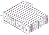
Referring to fig. 7 and 8 together, fig. 7 is a schematic structural diagram of a battery 10 according to another embodiment of the present invention. Fig. 8 is a schematic diagram of a first side of a battery 10 according to another embodiment of the present invention.
In other alternative embodiments, the first bus member 400 and the conductive member 200 may be integrally formed. The conductive member 200 is bounded by a dashed box in fig. 8, which does not constitute a structural limitation of the battery 10 in the embodiment of the present invention. The conductive member 200 is formed by extending outward from one side of the first bus member 400, for example, the conductive member 200 is formed by extending outward from one side of the first bus member 400 in the height direction (Z direction in fig. 2). This can simplify the structures of the conductive member 200 and the first bus member 400, and improve the stability and reliability of the connection between the conductive member 200 and the first bus member 400.
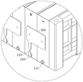
Referring to fig. 9, fig. 9 is a schematic view of a partial enlarged structure at I in fig. 7.
According to the battery 10 provided by the embodiment of the present invention, the conductive member 200 may be provided with a second fusing part 210, and the second fusing part 210 is fused when the current reaches a threshold value to break the electrode connecting part 120 and the case 110. When the current on the conductive member 200 reaches a threshold value, the second fusing part 210 fuses, so that the electrode connecting part 120 and the case 110 are disconnected, which can improve the safety of the battery 10.
Alternatively, the second fusing part 210 is formed by partially shrinking a section of the conductive member 200.
In these alternative embodiments, the second fuse portion 210 has a small partial cross-section. When the current reaches the threshold value, the second fusing part 210 may be fused prior to other portions of the conductive member 200. So that the conductive member 200 is disconnected by the position of the second fuse portion 210 and the electrical connection between the electrode connection portion 120 and the case 110 is broken.
In addition, the second fusing part 210 is formed by partially shrinking the cross-section of the conductive member 200, so that the structure of the conductive member 200 can be simplified, a fuse does not need to be disposed in the conductive member 200, the conductive member 200 can be easily formed and mounted, and the manufacturing and mounting costs of the battery 10 can be reduced.
In other embodiments, the second fuse portion 210 may also be a fuse built into the conductive member 200, for example.
Referring to fig. 7 and 8, when the conductive member 200 and the first bus member 400 are integrally formed, the conductive member 200 has a plate shape, the second fusing part 210 is formed by shrinking a partial section of the conductive member 200, and the width of the second fusing part 210 is smaller than the width of the other positions on the conductive member 200. The second fuse portion 210 is small in size, and when the current on the conductive member 200 reaches a threshold value, the second fuse portion 210 fuses before other portions of the conductive member 200 to form an open circuit.
When the conductive member 200 includes the first pin 220 and the second pin 230, the first pin 220 and the second pin 230 are connected to each other by the connection member 700, and the first fuse portion 710 is provided on the connection member 700, the conductive member 200 may be further provided with the second fuse portion 210. The second fuse portion 210 may be disposed on the first pin 220 and/or the second pin 230. The safety performance of the battery 10 can be further improved by the first and second fusing parts 710 and 210.
Referring to fig. 10 and 11 together, fig. 10 is a schematic structural diagram of a battery 10 according to another embodiment of the present invention. Fig. 11 shows a schematic structural diagram of a first side of a battery 10 according to yet another embodiment of the present invention.
In still other embodiments, the conductive member 200 is a metal wire, such as an aluminum wire or a copper wire. The conductive member 200 is connected between the first bus member 400 and the case 110. For example, one end of the conductive member 200 is connected to the first bus member 400 through a bonding process, and the other end of the conductive member 200 is connected to the case 110 through a bonding process. The sectional area of the wire is small, and when the current on the conductive member 200 reaches a threshold current, the wire can be broken, thereby breaking the circuit between the first bus member 400 and the case 110, and improving the safety of the battery 10.
The electrode connecting part 120 of the battery cell 100 is generally protruded from the outer surface of the case 110, and when the conductive member 200 is connected to the electrode connecting part 120, a certain height difference may exist between the conductive member 200 and the outer surface of the case 110, and the height difference may affect the stability of the connection of the conductive member 200 and the case 110.
With continued reference to fig. 9, in some alternative embodiments, the electrode connecting portion 120 extends from the outer surface of the housing 110 along a first direction (X direction in fig. 2); the case 110 is provided with a first connection portion 111, the conductive member 200 is provided with a second connection portion 240, at least one of the first connection portion 111 and the second connection portion 240 extends in a first direction, and the first connection portion 111 and the second connection portion 240 are connected to each other to connect the conductive member 200 to the case 110.
In these alternative embodiments, the difference in height of the electrode connection part 120 protruding from the outer surface of the case 110 can be compensated by the first connection part 111 and/or the second connection part 240, so that the connection of the conductive member 200 and the case 110 is more stable.
The first connection portion 111 and the second connection portion 240 are disposed in various ways, for example, the first connection portion 111 protrudes from the outer surface of the housing 110, and the second connection portion 240 is overlapped on the surface of the first connection portion 111 facing away from the housing 110. This can simplify the structure of the conductive member 200 and facilitate the assembly of the conductive member 200.
In these embodiments, optionally, the height of the first connection portion 111 protruding from the outer surface of the housing 110 is equal to or similar to the height of the electrode connection portion 120 protruding from the outer surface of the housing 110, so that the first connection portion 111 can compensate for the height difference of the electrode connection portion 120 protruding from the outer surface of the housing 110.
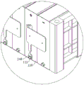
Referring to fig. 12, fig. 12 is another embodiment of a partial enlarged structural diagram at I in fig. 7.
In another embodiment, the first connecting portion 111 protrudes from the outer surface of the housing 110, and the second connecting portion 240 is disposed around the circumference of the first connecting portion 111, so that the stability of the connection between the first connecting portion 111 and the second connecting portion 240 can be improved.
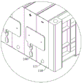
Referring to fig. 13, fig. 13 is a schematic diagram of a partial enlarged structure at I in fig. 7 according to another embodiment.
In still another embodiment, the second connection part 240 is formed by bending the conductive member 200 in a direction close to the surface of the case 110, so that the second connection part 240 can compensate for a height difference in which the electrode connection part 120 protrudes from the outer surface of the case 110.
In some alternative embodiments, the first connection portion 111 protrudes from the outer surface of the housing 110, and the second connection portion 240 is formed by bending the conductive member 200 in a direction close to the first connection portion 111, and the first connection portion 111 and the second connection portion 240 jointly compensate for a height difference of the electrode connection portion 120 protruding from the outer surface of the housing 110.
Optionally, the battery 10 further includes a side plate 11 and a fixing band 12, the side plate 11 is located on both sides of the plurality of battery units 100 in the thickness direction (i.e., Y direction in fig. 2), and the fixing band 12 surrounds the side plate 11 and the plurality of battery units 100.
The present invention may be embodied in other specific forms without departing from its spirit or essential characteristics. For example, the algorithms described in the specific embodiments may be modified without departing from the basic spirit of the invention. The present embodiments are therefore to be considered in all respects as illustrative and not restrictive, the scope of the invention being indicated by the appended claims rather than by the foregoing description, and all changes which come within the meaning and range of equivalency of the claims are therefore intended to be embraced therein.
Claims (12)
1. A battery, comprising:
the battery pack comprises at least two battery units and a battery pack, wherein the battery units are provided with a shell and two electrode connecting parts which are arranged on two sides of the shell and have opposite polarities, and each battery unit comprises a first battery unit and a second battery unit which are connected in series;
a conductive member disposed at one side of the case, the conductive member being for electrically connecting one of the two electrode connection parts of the first battery cell and the case of one of the first battery cell and the second battery cell;
the signal detection part is arranged on the other side of the shell and is provided with a signal detection circuit, the signal detection circuit is used for electrically connecting the other electrode connecting part of the first battery unit and the shell of the first battery unit and the second battery unit, and the signal detection circuit and the conductive part are electrically connected with the shell of the same battery unit, so that the signal detection circuit and the two electrode connecting parts of the first battery unit can form a detection loop through the shell and the conductive part of the same battery unit to realize the detection of the temperature or voltage signal of the first battery unit.
2. The battery of claim 1, further comprising:
a first bus member provided at one side of the case, the first bus member electrically connecting the electrode connection parts of the first and second battery cells to realize series connection;
the conductive member is used to electrically connect the first bus member and the housing.
3. The battery of claim 2, wherein the conductive member is formed by extending outward from one side of the first bus member.
4. The battery of claim 2, wherein the conductive member includes a first pin and a second pin connected to each other, the first pin for electrically connecting the first bus member, the second pin for electrically connecting the housing.
5. The battery of claim 4, wherein the first pin and the second pin are provided separately, the battery further comprising a connecting member for electrically connecting the first pin and the second pin.
6. The battery of claim 5, wherein the connecting member is provided with a first fuse for fusing when a current reaches a threshold value to form an open circuit between the first pin and the second pin.
7. The battery according to claim 2,
the two electrode connecting parts comprise a first electrode connecting part and a second electrode connecting part, the battery unit further comprises a third battery unit connected with the second battery unit in series, and the first electrode connecting part and the second electrode connecting part are sequentially and alternately distributed on the same side of the shell;
the first bus member is used to connect a first electrode connection part of the first battery cell and the second electrode connection part of the second battery cell;
the battery further includes a second bus member disposed at the other side of the case, the second bus member being used to connect the first electrode connection part of the second battery cell and the second electrode connection part of the third battery cell, and the signal detection line being used to electrically connect the second electrode connection part of the first battery cell, the second bus member, and the case.
8. The battery according to claim 1, wherein the conductive member is provided with a second fusing portion for fusing when a current reaches a threshold value to form an open circuit between the electrode connecting portion and the case.
9. The battery according to claim 8, wherein the second fusing portion is formed by partial cross-sectional contraction of the conductive member.
10. The battery according to claim 1,
the electrode connecting part extends out of the outer surface of the shell along a first direction;
the shell is provided with a first connecting portion, the conductive member is provided with a second connecting portion, at least one of the first connecting portion and the second connecting portion extends along the first direction, and the first connecting portion and the second connecting portion are connected with each other to connect the conductive member to the shell.
11. The battery according to claim 10,
the first connecting part is arranged to protrude out of the outer surface of the shell along the first direction;
the second connecting portion is lapped on the surface of the first connecting portion, which is deviated from the shell, or the second connecting portion is arranged around the periphery of the first connecting portion.
12. A device comprising a battery as claimed in any one of claims 1 to 11 for providing electrical energy.
Priority Applications (6)
| Application Number | Priority Date | Filing Date | Title |
|---|---|---|---|
| CN202011507137.8A CN112242594B (en) | 2020-12-18 | 2020-12-18 | Battery and device |
| PCT/CN2021/081760 WO2022126883A1 (en) | 2020-12-18 | 2021-03-19 | Battery and apparatus |
| JP2022538376A JP2023502545A (en) | 2020-12-18 | 2021-03-19 | Battery and device |
| KR1020227022174A KR102475576B1 (en) | 2020-12-18 | 2021-03-19 | battery and device |
| EP21904823.8A EP4068492A4 (en) | 2020-12-18 | 2021-03-19 | Battery and apparatus |
| US17/847,203 US20220336874A1 (en) | 2020-12-18 | 2022-06-23 | Battery and device |
Applications Claiming Priority (1)
| Application Number | Priority Date | Filing Date | Title |
|---|---|---|---|
| CN202011507137.8A CN112242594B (en) | 2020-12-18 | 2020-12-18 | Battery and device |
Publications (2)
| Publication Number | Publication Date |
|---|---|
| CN112242594A true CN112242594A (en) | 2021-01-19 |
| CN112242594B CN112242594B (en) | 2021-04-13 |
Family
ID=74175348
Family Applications (1)
| Application Number | Title | Priority Date | Filing Date |
|---|---|---|---|
| CN202011507137.8A Active CN112242594B (en) | 2020-12-18 | 2020-12-18 | Battery and device |
Country Status (6)
| Country | Link |
|---|---|
| US (1) | US20220336874A1 (en) |
| EP (1) | EP4068492A4 (en) |
| JP (1) | JP2023502545A (en) |
| KR (1) | KR102475576B1 (en) |
| CN (1) | CN112242594B (en) |
| WO (1) | WO2022126883A1 (en) |
Cited By (1)
| Publication number | Priority date | Publication date | Assignee | Title |
|---|---|---|---|---|
| WO2022126883A1 (en) * | 2020-12-18 | 2022-06-23 | 江苏时代新能源科技有限公司 | Battery and apparatus |
Citations (5)
| Publication number | Priority date | Publication date | Assignee | Title |
|---|---|---|---|---|
| JP2004152706A (en) * | 2002-11-01 | 2004-05-27 | Shin Kobe Electric Mach Co Ltd | Battery pack |
| JP2004362958A (en) * | 2003-06-05 | 2004-12-24 | Matsushita Electric Ind Co Ltd | Cell module |
| CN102354774A (en) * | 2011-09-23 | 2012-02-15 | 深圳先进储能材料国家工程研究中心有限公司 | Battery power supply device |
| CN103608946A (en) * | 2011-06-27 | 2014-02-26 | 株式会社Lg化学 | Battery module and battery assembly including same |
| CN206490144U (en) * | 2015-12-30 | 2017-09-12 | 奥沛特能源有限公司 | Battery component |
Family Cites Families (12)
| Publication number | Priority date | Publication date | Assignee | Title |
|---|---|---|---|---|
| JP4193328B2 (en) * | 2000-05-19 | 2008-12-10 | 新神戸電機株式会社 | Battery assembly, battery assembly and battery module |
| JP5128739B2 (en) * | 2001-09-03 | 2013-01-23 | 三洋電機株式会社 | Battery pack manufacturing method |
| JP3706576B2 (en) * | 2001-12-27 | 2005-10-12 | 三洋電機株式会社 | Power supply |
| DE102008010828A1 (en) * | 2008-02-23 | 2009-08-27 | Daimler Ag | Battery with several single cells |
| JP5825991B2 (en) * | 2011-11-21 | 2015-12-02 | 矢崎総業株式会社 | Wire cabling structure for storage batteries |
| KR101696001B1 (en) * | 2012-03-23 | 2017-01-12 | 삼성에스디아이 주식회사 | Secondary bttery module |
| US10244621B2 (en) * | 2013-08-28 | 2019-03-26 | Ford Global Technologies, Llc | Flex circuit system for a battery assembly of an electrified vehicle |
| KR101735875B1 (en) * | 2013-11-20 | 2017-05-15 | 삼성에스디아이 주식회사 | Secondary battery module |
| WO2017047258A1 (en) * | 2015-09-14 | 2017-03-23 | 日立オートモティブシステムズ株式会社 | Battery pack |
| JP6581958B2 (en) * | 2016-12-09 | 2019-09-25 | 矢崎総業株式会社 | Voltage detection structure and voltage detection module |
| DE102018212710A1 (en) * | 2018-07-31 | 2020-02-06 | Robert Bosch Gmbh | Electrical energy store, device and / or vehicle and method for producing an electrical energy store |
| CN112242594B (en) * | 2020-12-18 | 2021-04-13 | 江苏时代新能源科技有限公司 | Battery and device |
-
2020
- 2020-12-18 CN CN202011507137.8A patent/CN112242594B/en active Active
-
2021
- 2021-03-19 EP EP21904823.8A patent/EP4068492A4/en active Pending
- 2021-03-19 KR KR1020227022174A patent/KR102475576B1/en active IP Right Grant
- 2021-03-19 JP JP2022538376A patent/JP2023502545A/en active Pending
- 2021-03-19 WO PCT/CN2021/081760 patent/WO2022126883A1/en unknown
-
2022
- 2022-06-23 US US17/847,203 patent/US20220336874A1/en active Pending
Patent Citations (5)
| Publication number | Priority date | Publication date | Assignee | Title |
|---|---|---|---|---|
| JP2004152706A (en) * | 2002-11-01 | 2004-05-27 | Shin Kobe Electric Mach Co Ltd | Battery pack |
| JP2004362958A (en) * | 2003-06-05 | 2004-12-24 | Matsushita Electric Ind Co Ltd | Cell module |
| CN103608946A (en) * | 2011-06-27 | 2014-02-26 | 株式会社Lg化学 | Battery module and battery assembly including same |
| CN102354774A (en) * | 2011-09-23 | 2012-02-15 | 深圳先进储能材料国家工程研究中心有限公司 | Battery power supply device |
| CN206490144U (en) * | 2015-12-30 | 2017-09-12 | 奥沛特能源有限公司 | Battery component |
Cited By (2)
| Publication number | Priority date | Publication date | Assignee | Title |
|---|---|---|---|---|
| WO2022126883A1 (en) * | 2020-12-18 | 2022-06-23 | 江苏时代新能源科技有限公司 | Battery and apparatus |
| JP2023502545A (en) * | 2020-12-18 | 2023-01-24 | 江▲蘇▼▲時▼代新能源科技有限公司 | Battery and device |
Also Published As
| Publication number | Publication date |
|---|---|
| JP2023502545A (en) | 2023-01-24 |
| US20220336874A1 (en) | 2022-10-20 |
| EP4068492A1 (en) | 2022-10-05 |
| KR20220108124A (en) | 2022-08-02 |
| EP4068492A4 (en) | 2023-08-02 |
| KR102475576B1 (en) | 2022-12-08 |
| CN112242594B (en) | 2021-04-13 |
| WO2022126883A1 (en) | 2022-06-23 |
Similar Documents
| Publication | Publication Date | Title |
|---|---|---|
| EP3346517B1 (en) | Battery system | |
| US20240106084A1 (en) | Battery cell, battery, power consumption device, and method and device for producing battery cell | |
| KR20170140694A (en) | Battery module, battery pack comprising the battery module and vehicle comprising the battery pack | |
| CN216085053U (en) | Battery and electric equipment | |
| CN214589171U (en) | Battery and power consumption device | |
| CN218414641U (en) | End cover assembly, battery and electric equipment | |
| CN112242594B (en) | Battery and device | |
| US20230395952A1 (en) | Battery cell, battery and electrical device | |
| CN112259872A (en) | Battery, electric equipment and manufacturing method of battery | |
| CN115425372B (en) | Electrode pole piece, electrode component, battery monomer, battery and consumer | |
| CN217768705U (en) | Pole piece structure, electric core subassembly, battery monomer, battery and power consumption device | |
| US20230275287A1 (en) | Battery, power consumption device, and method and device for producing battery | |
| CN216872190U (en) | Battery and consumer | |
| WO2023133748A1 (en) | Battery module, battery, electrical device, and method and device for preparing battery | |
| US20230026926A1 (en) | Battery, power consumption device, and method and device for producing battery | |
| CN115084782A (en) | Electrode assembly, battery cell, battery and power consumption device | |
| CN115968515A (en) | Battery, electric equipment, method and equipment for preparing battery | |
| US20240006687A1 (en) | Battery, electric device, and method and device for preparing battery cell | |
| CN215496869U (en) | End cover assembly, battery monomer, battery and consumer | |
| CN217158566U (en) | Battery and electric equipment | |
| CN220510204U (en) | Connection assembly, battery and electricity utilization device | |
| US11830996B1 (en) | Battery, power consuming apparatus, and method and apparatus for manufacturing battery | |
| CN216213725U (en) | Battery cell, battery and consumer | |
| EP4071922A1 (en) | Battery, electric apparatus, battery preparation method and battery preparation apparatus | |
| US20230361436A1 (en) | Battery, electric device, and manufacturing method and manufacturing device of battery |
Legal Events
| Date | Code | Title | Description |
|---|---|---|---|
| PB01 | Publication | ||
| PB01 | Publication | ||
| SE01 | Entry into force of request for substantive examination | ||
| SE01 | Entry into force of request for substantive examination | ||
| GR01 | Patent grant | ||
| GR01 | Patent grant |