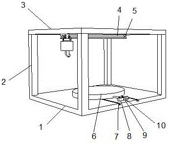
Movable track for movable laser cleaning equipment
Technical Field
The invention relates to the technical field of laser cleaning equipment, in particular to a movable track for movable laser cleaning equipment.
Background
The laser cleaning industry has various cleaning modes, and most of the cleaning modes are cleaning by using chemical agents and mechanical methods. Nowadays, the requirements of environmental protection regulations in China are more and more strict, and people are more and more aware of environment protection and safety, the types of chemicals which can be used in industrial production and cleaning become less and less. How to find a cleaner and non-damaging cleaning method is a problem which has to be considered. Laser cleaning has the characteristics of no grinding, no contact, no thermal effect, suitability for objects made of various materials and the like, and is considered to be the most reliable and effective solution. Meanwhile, the laser cleaning can solve the problem which cannot be solved by adopting the traditional cleaning mode.
When the existing mobile laser cleaning equipment on the market is used, due to the fact that no matched track is arranged, the position of the laser cleaning equipment needs to be changed repeatedly in the cleaning process, the cleaning mode is low in efficiency, and the use of the existing industrial equipment cannot be met. For this reason, we propose a moving track for a mobile laser cleaning apparatus.
Disclosure of Invention
The invention mainly solves the technical problems in the prior art and provides a movable track for movable laser cleaning equipment.
In order to achieve the purpose, the invention adopts the following technical scheme that the movable rail for the movable laser cleaning equipment comprises a bottom plate, wherein the bottom plate is a rectangular plate, four corners of the upper end of the bottom plate are vertically and upwards fixedly provided with support rods, the support rods are rectangular long rods, the upper ends of four groups of support rods are fixedly provided with a top plate in parallel, the top plate is a rectangular plate, the shape and the specification of the top plate are consistent with those of the bottom plate, the middle position of the lower end of the top plate is fixedly provided with the movable rail, the movable rail is an arc-shaped rail, sliding grooves are respectively formed in the inner ring and the outer ring of the movable rail, the sliding grooves are arc-shaped grooves with rectangular cross sections, the middle position of the upper end of the bottom plate is provided with a fixed table, the fixed table is a circular table, two groups of adjusting grooves are parallelly formed in the front side of, the fixed table is connected inside the adjusting groove in a sliding manner through two groups of trapezoidal sliding blocks, the front side of the upper end of the bottom plate is fixedly provided with a fixed block corresponding to the position of the fixed table, the fixed block is a rectangular block, the middle position of the fixed block is provided with a threaded hole, the inner part of the threaded hole is connected with an adjusting screw rod in a threaded manner, the adjusting screw rod is a long rod with threads at the excircle, one end of the adjusting screw rod close to the fixed table is fixedly connected with the fixed table through a bearing, a rotating disk is fixedly arranged at one end of the adjusting screw rod at the front side of the fixed block, the rotating disk is a circular plate, the inner parts of the two groups of sliding grooves are symmetrically connected with sliding clamping blocks in a sliding manner, the sliding clamping blocks are arc-shaped blocks, a fixed support is fixedly arranged below the two groups of sliding clamping blocks, the fixed support is of, the lower end of the fixed bracket is fixedly provided with a movable box which is a cylindrical hollow box, the middle position of the lower end of the movable box is provided with a middle hole, the middle hole is a rectangular groove, the inside of the middle hole is vertically and slidably connected with a telescopic rod, the telescopic rod is a rectangular long rod, the middle position of the top end inside the movable box is fixedly provided with a motor, a lower end rotor of the motor is fixedly provided with a rotating shaft, the rotating shaft is a cylindrical rod, the lower end of the rotating shaft is fixedly provided with a fixed rotating disk in parallel, the fixed rotating disk is a circular plate, the lower end of the fixed rotating disk is fixedly provided with an extrusion ring, the lower end surface of the extrusion ring is a spiral annular block, the top of one end inside the movable box is fixedly provided with a supporting plate in parallel, the supporting plate is a circular plate, the upper end of the edge, the empty avoiding groove is a rectangular groove, the middle position in the empty avoiding groove is movably connected with an extrusion wheel through a rotating shaft, the extrusion wheel is a round wheel, the highest point of the extrusion wheel is tightly attached to the lower end face of an extrusion ring, the four corners of the lower end of a supporting plate are vertically and downwards fixedly provided with springs, one end of each spring, which is far away from the supporting plate, is fixedly connected with the bottom end in the moving box, one side face, which is close to the circle center position of a moving track, of a telescopic rod is provided with a side groove, the side groove is a rectangular groove, the upper end and the lower end in the side groove are respectively and fixedly provided with a magnetic block, each magnetic block is a rectangular block with magnetism, the inner part of each side groove is vertically and slidably connected with a moving magnetic rod, each moving magnetic rod is a rectangular long rod with magnetism, the surface, which is close to two groups of magnetic blocks, of the moving magnetic rod, the one end fixed mounting that the side groove was kept away from to the removal magnetic pole has the removal shell, and the removal shell is the rectangular block, and the front of removal shell has been seted up and has been rocked the groove, rocks the groove and be the rectangular channel, and there is laser emission pole in the inside intermediate position of rocking the groove through pivot movable mounting, and laser emission pole has the laser emission head at the one end fixed mounting who rocks the groove outside, and the terminal fixed mounting of laser emission pole has the gangbar, and the gangbar is cylindrical stock, rocks the inside bottom in groove and has seted up the arc wall.
Preferably, the arc-shaped groove is an arc-shaped groove, the arc center of the arc-shaped groove coincides with the rotating shaft at the middle position of the laser emitting rod, and one end, away from the laser emitting rod, of the linkage rod is movably provided with a swinging wheel and the swinging wheel is connected inside the arc-shaped groove in a sliding mode.
Preferably, the bottom end of the inside of the sliding chute is arc-shaped, a circle of supporting auxiliary wheel is movably mounted through a rotating shaft, the supporting auxiliary wheel is a round wheel, a balance rod is arranged at the upper end of the inside of the sliding chute in parallel, and the balance rod is an annular rod with a rectangular cross section.
Preferably, a row of compression springs are fixedly installed at the upper end of the balance rod at equal intervals, and one ends of the compression springs, far away from the balance rod, are fixedly connected with the top end of the inner side of the sliding groove.
Preferably, the lower end of the balancing rod is movably provided with a row of auxiliary extrusion wheels at equal intervals through a rotating shaft, and the auxiliary extrusion wheels are round wheels with the same shape and specification as the supporting auxiliary wheels.
Advantageous effects
The invention provides a movable track for movable laser cleaning equipment. The method has the following beneficial effects:
(1) this portable laser cleaning equipment is with removing track, the work piece that will clear up is placed and is fixed through anchor clamps in the upper end of fixed station, it is rotatory to make the rotary disk drive adjusting screw through rotatory rotary disk, adjusting screw passes through the screw hole screw-thread fit removal of screw thread and fixed block intermediate position, adjusting screw can the back-and-forth movement this moment, adjusting screw and fixed station pass through the bearing and connect, adjusting screw can drive the fixed station back-and-forth movement this moment, the fixed station passes through the up end back-and-forth movement of the sliding connection of two sets of sliders of lower extreme and adjustment tank at the bottom plate, adjust the position of whole fixed station, conveniently adjust the front and back position that the fixed station upper end needs the washing work piece, the skew is gone beyond the working range of whole cleaning equipment and is leaded to the.
(2) This portable laser cleaning equipment is with removing the track, two sets of slip clamp piece slide in the inside of both sides spout, the slip clamp piece drives fixed bolster and removes the case and through removing the track semicircular in shape slip, removes the case this moment and passes through the telescopic link and drive laser emission pole and laser emission head and be annular removal and call annular clearance to whole work piece to make the work piece once fix can remove the case and realize clearing up the latter half circle of work piece comprehensively, improved equipment work efficiency greatly.
(3) This portable laser cleaning equipment is with removing the track, makes laser emitting rod and laser emitting head can be slowly at the uniform velocity the removal through adding removal track and spout, increases the stability of whole device, guarantees that laser emitting rod and laser emitting head can reach the effect of clearance on a large scale when removing, improves whole cleaning equipment's efficiency.
(4) The movable track for the laser cleaning equipment comprises a motor, a rotating shaft, a supporting plate, an extrusion rod, an extrusion wheel, an extrusion ring, a fixed rotating disc, a supporting plate, a motor, a fixed rotating disc, an extrusion ring, a supporting plate, an extrusion rod, an extrusion ring, a middle hole and an extrusion ring, wherein the rotating shaft is driven to rotate by the fixed rotating disc, the supporting plate moves upwards under the action of the elastic force of two groups of springs, the supporting plate drives the extrusion rod to move upwards at the moment, the extrusion wheel and the lower end face of the extrusion ring are tightly extruded to ensure that the extrusion ring can be extruded by the extrusion wheel and the lower end face of the extrusion ring during rotation, the whole supporting plate can periodically change the height, so that the expansion rod is driven to periodically slide upwards and downwards through the middle hole, when the extrusion wheel moves to the position with the longest, guarantee abluent clean degree, and the movable box telescopic link can periodically reciprocate when being the annular removal and relapse laser irradiation vibrations to certain position, guarantee abluent clean degree.
(5) When the telescopic rod moves up and down, the movable magnetic rod can also move up and down along with the telescopic rod, the moving magnetic force rod can be suspended in the side groove by the magnetic repulsion of the moving magnetic force rod and the two groups of magnetic blocks, when the telescopic rod moves up and down, the movable magnetic rod can vibrate downwards periodically under the repulsion of the magnetic force of the two groups of magnetic blocks, at the moment, the movable magnetic rod drives the movable shell to vibrate up and down repeatedly, the laser emitting rod overturns through the rotating shaft at the middle position when the movable shell vibrates, the laser emitting head at the front end of the laser emitting rod and the swinging wheel swing up and down in opposite directions, therefore, the whole laser emitting head and the laser emitting rod can periodically swing up and down at high frequency in a small vertical area to perform sector cleaning, each part of a workpiece can be repeatedly washed with high intensity, and the condition that the cleaning is not complete due to less times of cleaning the position with heavy local stains is avoided.
(6) The movable type laser cleaning equipment is provided with a movable track, two groups of sliding clamping blocks are connected inside a sliding groove in a sliding mode, the lower end face of each sliding clamping block can be tightly attached to a supporting auxiliary wheel by arranging the supporting auxiliary wheel, the lower end face of each sliding clamping block is in contact with the supporting auxiliary wheel when the sliding clamping blocks slide inside the sliding groove, the lower end face of each sliding clamping block can be reduced by adding the supporting auxiliary wheel, friction force sliding in contact with the sliding groove is generated, the supporting auxiliary wheel assists the sliding clamping blocks to move, a balance rod moves downwards under the elastic action of an extrusion spring, the auxiliary extrusion wheel is driven to move downwards through the movement of the balance rod to extrude the upper end face of each sliding clamping block, the auxiliary extrusion wheel and the supporting auxiliary wheel fix the sliding clamping blocks inside the sliding groove, the problem that the sliding clamping blocks cannot bump up and down when sliding inside the sliding groove is guaranteed, the auxiliary extrusion wheel and the supporting auxiliary wheel clamp the sliding clamping blocks to clamp the sliding clamping blocks, and guarantee And (4) sex.
(7) This portable laser cleaning equipment is with removing track, make when foreign matter or impurity appear inside the spout through adding the extrusion spring, the tight piece extrusion of slip clamp can make the tight piece rebound of slip clamp above impurity, the tight piece of slip clamp makes progress the extrusion wheel of supplementary extrusion and makes balancing pole extrusion spring shrink this moment, can guarantee through adding the extrusion spring that the tight piece up end of slip clamp leaves the distance of buffering, the tight piece of whole slip clamp can appear card shell or the too big condition that leads to the damage of wearing and tearing takes place when preventing the inside foreign matter that appears of spout.
Drawings
FIG. 1 is an overall schematic view of the present invention;
FIG. 2 is a detailed view of the moving track of the present invention;
FIG. 3 is a schematic view of the interior of the travel box of the present invention;
FIG. 4 is a detailed view of the extrusion ring of the present invention;
FIG. 5 is a detailed view of the interior of the mobile housing of the present invention;
fig. 6 is a detailed view of the inside of the chute of the present invention.
Illustration of the drawings:
1 bottom plate, 2 supporting rods, 3 top plate, 4 moving track, 5 sliding grooves, 6 fixed table, 7 adjusting groove, 8 fixed block, 9 adjusting screw, 10 rotating disc, 11 sliding clamping block, 12 fixed support, 13 moving box, 14 telescopic rod, 15 motor, 16 rotating shaft, 17 fixed rotating disc, 18 extrusion ring, 19 supporting plate, 20 extrusion rod, 21 middle hole, 22 spring, 23 clearance groove, 24 extrusion wheel, 25 side groove, 26 magnetic block, 27 moving magnetic rod, 28 moving shell, 29 shaking groove, 30 arc groove, 31 laser emission rod, 32 laser emission head, 33 linkage rod, 34 swinging wheel, 35 supporting auxiliary wheel, 36 balancing rod, 37 extrusion spring and 38 auxiliary extrusion wheel.
Detailed Description
In order to make the technical means, the creation characteristics, the achievement purposes and the effects of the invention easy to understand, the invention is further described with the specific embodiments.
Example (b): a movable track for a movable laser cleaning device is shown in figures 1-6 and comprises a bottom plate 1, wherein the bottom plate 1 is a rectangular plate, four corners of the upper end of the bottom plate 1 are vertically upwards fixedly provided with support rods 2, the support rods 2 are rectangular long rods, the upper ends of four groups of support rods 2 are fixedly provided with a top plate 3 in parallel, the top plate 3 is a rectangular plate, the shape and the specification of the top plate 3 are consistent with those of the bottom plate 1, the middle position of the lower end of the top plate 3 is fixedly provided with a movable track 4, the movable track 4 is an arc track, the inner ring and the outer ring of the movable track 4 are respectively provided with a sliding chute 5, the sliding chute 5 is an arc-shaped groove with a rectangular cross section, the middle position of the upper end of the bottom plate 1 is provided with a fixed table 6, the fixed table 6 is a circular table, the front side of the upper end of the bottom plate 1 is provided with two groups of adjusting grooves 7, the fixed table 6 is connected inside the adjusting groove 7 in a sliding manner through two groups of trapezoidal sliding blocks, the front side of the upper end of the bottom plate 1 is fixedly provided with a fixed block 8 corresponding to the position of the fixed table 6, the fixed block 8 is a rectangular block, the middle position of the fixed block 8 is provided with a threaded hole, the inner thread of the threaded hole is connected with an adjusting screw 9, the adjusting screw 9 is a long rod with threads arranged at the excircle, one end of the adjusting screw 9 close to the fixed table 6 is fixedly connected with the fixed table 6 through a bearing, one end of the adjusting screw 9 at the front side of the fixed block 8 is fixedly provided with a rotating disk 10, the rotating disk 10 is a circular plate, the inner parts of the two groups of sliding grooves 5 are symmetrically and slidably connected with sliding clamping blocks 11, the sliding clamping blocks 11 are arc-shaped blocks, a fixed support 12 is fixedly arranged below the, the upper ends of arc-shaped rods on two side edges of a fixed support 12 are fixedly connected with one end face of each of two groups of sliding clamping blocks 11, the lower end of the fixed support 12 is fixedly provided with a movable box 13, the movable box 13 is a cylindrical hollow box, the middle position of the lower end of the movable box 13 is provided with a middle hole 21, the middle hole 21 is a rectangular groove, the inside of the middle hole 21 is vertically and slidably connected with an expansion link 14, the expansion link 14 is a rectangular long rod, the middle position of the top end inside the movable box 13 is fixedly provided with a motor 15, a lower end rotor of the motor 15 is fixedly provided with a rotating shaft 16, the rotating shaft 16 is a cylindrical rod, the lower end of the rotating shaft 16 is fixedly provided with a fixed rotating disk 17 in parallel, the fixed rotating disk 17 is a circular plate, the lower end of the fixed rotating disk 17 is fixedly provided with an extrusion ring 18, the extrusion ring 18 is, the supporting plate 19 is a circular plate, the upper end of the edge of the supporting plate 19 is vertically and upwards fixedly provided with an extrusion rod 20, the extrusion rod 20 is a rectangular rod, the middle position of the upper end of the extrusion rod 20 is provided with an empty avoiding groove 23, the empty avoiding groove 23 is a rectangular groove, the middle position inside the empty avoiding groove 23 is movably connected with an extrusion wheel 24 through a rotating shaft, the extrusion wheel 24 is a circular wheel, the highest point of the extrusion wheel 24 is tightly attached to the lower end face of the extrusion ring 18, the four corners of the lower end of the supporting plate 19 are vertically and downwards fixedly provided with springs 22, one end of each spring 22 far away from the supporting plate 19 is fixedly connected with the bottom end inside the movable box 13, one side face of the telescopic rod 14 close to the circle center position of the movable track 4 is provided with a side groove 25, the side groove 25 is a rectangular groove, the upper end and the lower end inside the side groove 25 are fixedly provided with magnetic blocks 26, each magnetic block 26 is a rectangular block, the movable magnetic rod 27 is a magnetic rectangular long rod, the surfaces of the movable magnetic rod 27 and the two groups of magnetic blocks 26, which are close to each other, are opposite to the magnetic poles of the magnetic blocks 26, the movable magnetic rod 27 is suspended and slidably connected inside the side groove 25, one end of the movable magnetic rod 27, which is far away from the side groove 25, is fixedly provided with a movable shell 28, the movable shell 28 is a rectangular block, the front surface of the movable shell 28 is provided with a shaking groove 29, the shaking groove 29 is a rectangular groove, the middle position inside the shaking groove 29 is movably provided with a laser emission rod 31 through a rotating shaft, one end of the laser emission rod 31, which is outside the shaking groove 29, is fixedly provided with a laser emission head 32, the laser emission rod 31 and the laser emission head 32 are in the prior art, so that the description is omitted, the tail end of the laser emission rod 31 is fixedly provided with a linkage rod 33, the linkage rod 33 is a cylindrical long rod, the inner bottom, arc wall 30 is the coincidence of the pivot of arc center and laser emission pole 31 intermediate position of arc wall and arc wall 30, the one end that laser emission pole 31 was kept away from to gangbar 33 has rocking wheel 34 and rocking wheel 34 sliding connection in the inside of arc wall 30 through pivot movable mounting, the inside bottom of spout 5 is the arc and has the round through pivot movable mounting to support auxiliary wheel 35, it is circular wheel to support auxiliary wheel 35, the inside upper end parallel arrangement of spout 5 has balancing pole 36, balancing pole 36 is the annular pole that the cross section is the rectangle, the upper end equidistance fixed mounting of balancing pole 36 has one row of extrusion spring 37, the one end that balancing pole 36 was kept away from to extrusion spring 37 and the inboard top fixed connection of spout 5, the lower extreme equidistance of balancing pole 36 has one row of supplementary extrusion wheels 38 through pivot movable mounting, supplementary extrusion wheel 38 is the circular wheel unanimous with the supporting auxiliary wheel 35 shape specification.
The working principle of the invention is as follows:
when the cleaning device is used, a workpiece to be cleaned is placed at the upper end of the fixed table 6 and is fixed through the fixture, the rotating disc 10 is rotated to enable the rotating disc 10 to drive the adjusting screw rod 9 to rotate, the adjusting screw rod 9 moves in a threaded matching mode with a threaded hole in the middle position of the fixed block 8 through threads, the adjusting screw rod 9 can move back and forth at the moment, the adjusting screw rod 9 is connected with the fixed table 6 through a bearing, the adjusting screw rod 9 can drive the fixed table 6 to move back and forth at the moment, the fixed table 6 is connected with the upper end face of the bottom plate 1 to move back and forth through the two groups of sliders at the lower end and the sliding connection of the adjusting groove 7, the position of the whole fixed table 6 is adjusted, the front and back positions of the workpiece to be cleaned at the upper end of the fixed table.
Two sets of slip clamp piece 11 slide in the inside of both sides spout 5, and slip clamp piece 11 drives fixed bolster 12 and movable box 13 and is the semicircular in shape slip through moving track 4, and movable box 13 drives laser emission pole 31 and laser emission head 32 through telescopic link 14 and is the annular removal to whole work piece title annular clearance this moment to make the work piece once fix can remove movable box 13 and realize clearing up the latter half circle of work piece comprehensively, improved equipment work efficiency greatly.
Make laser emission pole 31 and laser emission head 32 can slowly be at the uniform velocity the removal through adding removal track 4 and spout 5, increase the stability of whole device, guarantee that laser emission pole 31 and laser emission head 32 can reach the effect of clearance on a large scale when removing, improve whole cleaning equipment's efficiency.
The motor 15 drives the rotating shaft 16 to rotate under the control of an external controller, the rotating shaft 16 drives the extrusion ring 18 to rotate through the fixed rotating disk 17, the support plate 19 moves upwards under the action of the elastic force of the two groups of springs 22, at the moment, the support plate 19 drives the extrusion rod 20 to move upwards, the extrusion wheel 24 is tightly extruded with the lower end surface of the extrusion ring 18, so that the extrusion ring 18 can be extruded with the lower end surface of the extrusion ring 18 through the extrusion wheel 24 when rotating, the whole support plate 19 can be periodically changed in height, the telescopic rod 14 is driven to periodically slide up and down through the middle hole 21, when the extrusion wheel 24 moves to the position with the longest length of the extrusion ring 18, the extrusion wheel 24 can be contacted with the lower end surface of the fixed rotating disk 17 under the elastic action of the two groups of springs 22 to perform next extrusion, the whole telescopic rod 14 can periodically move up and down through the addition of the extrusion ring 18, guarantee abluent clean degree, and the movable box 13 telescopic link 14 can reciprocate periodically when being the annular removal and carry out the vibrations of laser irradiation repeatedly to certain position, guarantee abluent clean degree.
When the telescopic rod 14 moves up and down, the moving magnetic rod 27 also moves up and down along with the telescopic rod 14, the moving magnetic rods 27 can be suspended inside the side slots 25 by the magnetic repulsion of the moving magnetic rods 27 with the two sets of magnetic blocks 26, when the telescopic rod 14 moves up and down, the moving magnetic rod 27 will periodically vibrate downward under the magnetic repulsion of the two groups of magnetic blocks 26, and at the same time, the moving magnetic rod 27 drives the moving shell 28 to repeatedly vibrate up and down, the laser emitting rod 31 is turned over through the rotating shaft at the middle position when the moving shell 28 vibrates, the laser emitting head 32 at the front end of the laser emitting rod 31 and the swinging wheel 34 swing up and down in opposite directions, therefore, the whole laser emitting head 32 and the laser emitting rod 31 can periodically swing up and down at high frequency in a small vertical area to perform sector cleaning, each part of a workpiece can be repeatedly washed with high intensity, and the condition that the cleaning is incomplete due to the fact that the cleaning times of the position with heavy local stains are few is avoided.
The two groups of sliding clamping blocks 11 are connected inside the sliding chute 5 in a sliding manner, the lower end face of each sliding clamping block 11 can be tightly attached to the supporting auxiliary wheel 35 by arranging the supporting auxiliary wheel 35, the lower end face of each sliding clamping block 11 is in contact with the supporting auxiliary wheel 35 when the sliding clamping block 11 slides inside the sliding chute 5, the lower end face of each sliding clamping block 11 can be reduced by adding the supporting auxiliary wheel 35, the friction force of the sliding clamping block 11 in contact sliding with the sliding chute 5 is reduced, the supporting auxiliary wheel 35 assists the sliding clamping block 11 to move, the balance rod 36 moves downwards under the action of the elastic force of the extrusion spring 37, the auxiliary extrusion wheel 38 is driven by the movement of the balance rod 36 to move downwards to extrude the upper end face of the sliding clamping block 11, and at the moment, the auxiliary extrusion wheel 38 and the supporting auxiliary wheel 35 extrude the sliding clamping block 11 inside the sliding chute 5 to be fixed, so that the problem, the auxiliary pressing wheel 38 and the supporting auxiliary wheel 35 are used for clamping the sliding clamping block 11, so that the sliding clamping block 11 can keep smooth performance during sliding.
Make when the inside foreign matter that appears of spout 5 or impurity through adding extrusion spring 37, the extrusion of the tight piece of slip clamp 11 can make the tight piece of slip clamp 11 upwards move on impurity, and the tight piece of slip clamp 11 upwards extrudees supplementary pinch roller 38 and makes balancing pole 36 extrusion spring 37 upwards contract this moment, can guarantee through adding extrusion spring 37 that the tight piece 11 up end of slip clamp leaves the distance of buffering, and the tight piece of the tight piece 11 of the whole slip clamp can appear card shell or wear out too greatly and lead to the condition of damage to take place when preventing the inside foreign matter that appears of spout 5.
The foregoing shows and describes the general principles and broad features of the present invention and advantages thereof. It will be understood by those skilled in the art that the present invention is not limited to the embodiments described above, which are described in the specification and illustrated only to illustrate the principle of the present invention, but that various changes and modifications may be made therein without departing from the spirit and scope of the present invention, which fall within the scope of the invention as claimed. The scope of the invention is defined by the appended claims and equivalents thereof.