CN112196469B - Pile expanding equipment for bridge pile foundation - Google Patents
Pile expanding equipment for bridge pile foundation Download PDFInfo
- Publication number
- CN112196469B CN112196469B CN202011124270.5A CN202011124270A CN112196469B CN 112196469 B CN112196469 B CN 112196469B CN 202011124270 A CN202011124270 A CN 202011124270A CN 112196469 B CN112196469 B CN 112196469B
- Authority
- CN
- China
- Prior art keywords
- pile
- guide cylinder
- expanding guide
- expanding
- pile expanding
- Prior art date
- Legal status (The legal status is an assumption and is not a legal conclusion. Google has not performed a legal analysis and makes no representation as to the accuracy of the status listed.)
- Active
Links
- 238000001125 extrusion Methods 0.000 claims abstract description 5
- 238000003756 stirring Methods 0.000 claims description 7
- 230000003014 reinforcing effect Effects 0.000 claims description 5
- 230000000087 stabilizing effect Effects 0.000 claims 1
- 239000002689 soil Substances 0.000 abstract description 15
- 238000009434 installation Methods 0.000 abstract description 6
- 230000003028 elevating effect Effects 0.000 description 5
- 238000010276 construction Methods 0.000 description 3
- 239000003381 stabilizer Substances 0.000 description 2
- 238000006467 substitution reaction Methods 0.000 description 2
- 230000009286 beneficial effect Effects 0.000 description 1
- 238000010586 diagram Methods 0.000 description 1
- 230000004048 modification Effects 0.000 description 1
- 238000012986 modification Methods 0.000 description 1
Images


Classifications
-
- E—FIXED CONSTRUCTIONS
- E21—EARTH OR ROCK DRILLING; MINING
- E21B—EARTH OR ROCK DRILLING; OBTAINING OIL, GAS, WATER, SOLUBLE OR MELTABLE MATERIALS OR A SLURRY OF MINERALS FROM WELLS
- E21B7/00—Special methods or apparatus for drilling
- E21B7/28—Enlarging drilled holes, e.g. by counterboring
-
- E—FIXED CONSTRUCTIONS
- E21—EARTH OR ROCK DRILLING; MINING
- E21B—EARTH OR ROCK DRILLING; OBTAINING OIL, GAS, WATER, SOLUBLE OR MELTABLE MATERIALS OR A SLURRY OF MINERALS FROM WELLS
- E21B10/00—Drill bits
- E21B10/26—Drill bits with leading portion, i.e. drill bits with a pilot cutter; Drill bits for enlarging the borehole, e.g. reamers
-
- E—FIXED CONSTRUCTIONS
- E21—EARTH OR ROCK DRILLING; MINING
- E21B—EARTH OR ROCK DRILLING; OBTAINING OIL, GAS, WATER, SOLUBLE OR MELTABLE MATERIALS OR A SLURRY OF MINERALS FROM WELLS
- E21B10/00—Drill bits
- E21B10/62—Drill bits characterised by parts, e.g. cutting elements, which are detachable or adjustable
-
- E—FIXED CONSTRUCTIONS
- E21—EARTH OR ROCK DRILLING; MINING
- E21B—EARTH OR ROCK DRILLING; OBTAINING OIL, GAS, WATER, SOLUBLE OR MELTABLE MATERIALS OR A SLURRY OF MINERALS FROM WELLS
- E21B15/00—Supports for the drilling machine, e.g. derricks or masts
- E21B15/003—Supports for the drilling machine, e.g. derricks or masts adapted to be moved on their substructure, e.g. with skidding means; adapted to drill a plurality of wells
-
- E—FIXED CONSTRUCTIONS
- E21—EARTH OR ROCK DRILLING; MINING
- E21B—EARTH OR ROCK DRILLING; OBTAINING OIL, GAS, WATER, SOLUBLE OR MELTABLE MATERIALS OR A SLURRY OF MINERALS FROM WELLS
- E21B19/00—Handling rods, casings, tubes or the like outside the borehole, e.g. in the derrick; Apparatus for feeding the rods or cables
- E21B19/08—Apparatus for feeding the rods or cables; Apparatus for increasing or decreasing the pressure on the drilling tool; Apparatus for counterbalancing the weight of the rods
- E21B19/081—Screw-and-nut feed mechanisms
-
- E—FIXED CONSTRUCTIONS
- E21—EARTH OR ROCK DRILLING; MINING
- E21B—EARTH OR ROCK DRILLING; OBTAINING OIL, GAS, WATER, SOLUBLE OR MELTABLE MATERIALS OR A SLURRY OF MINERALS FROM WELLS
- E21B19/00—Handling rods, casings, tubes or the like outside the borehole, e.g. in the derrick; Apparatus for feeding the rods or cables
- E21B19/10—Slips; Spiders ; Catching devices
-
- E—FIXED CONSTRUCTIONS
- E21—EARTH OR ROCK DRILLING; MINING
- E21B—EARTH OR ROCK DRILLING; OBTAINING OIL, GAS, WATER, SOLUBLE OR MELTABLE MATERIALS OR A SLURRY OF MINERALS FROM WELLS
- E21B7/00—Special methods or apparatus for drilling
- E21B7/02—Drilling rigs characterised by means for land transport with their own drive, e.g. skid mounting or wheel mounting
- E21B7/024—Drilling rigs characterised by means for land transport with their own drive, e.g. skid mounting or wheel mounting having means for adapting to inclined terrain; having means for stabilizing the vehicle while drilling
Landscapes
- Engineering & Computer Science (AREA)
- Life Sciences & Earth Sciences (AREA)
- Geology (AREA)
- Mining & Mineral Resources (AREA)
- Physics & Mathematics (AREA)
- Environmental & Geological Engineering (AREA)
- Fluid Mechanics (AREA)
- General Life Sciences & Earth Sciences (AREA)
- Geochemistry & Mineralogy (AREA)
- Mechanical Engineering (AREA)
- Placing Or Removing Of Piles Or Sheet Piles, Or Accessories Thereof (AREA)
- Piles And Underground Anchors (AREA)
Abstract
The invention discloses pile expanding equipment for a bridge pile foundation, which comprises a frame body and a pile expanding guide cylinder, wherein the upper end part of the frame body is provided with a lifting mechanism, the side wall of the middle part of the pile expanding guide cylinder is provided with a connecting sleeve body sleeved on the pile expanding guide cylinder, the end part of a lower arm of an installation support is connected with the side wall of the connecting sleeve body through a universal joint, the upper end part of the pile expanding guide cylinder is provided with a toggle ring assembly sleeved outside the pile expanding guide cylinder, the bottom end part of the pile expanding guide cylinder is provided with an eccentric rotating shaft and a lower support, the eccentric rotating shaft is rotatably installed on the pile expanding guide cylinder, and an adjusting toggle assembly for toggling the eccentric rotating shaft to rotate and adjust. The pile foundation hole expanding device is simple in structure, the diameter of a pile foundation hole is increased by utilizing outward expanding rotation of the bottom of the pile expanding guide cylinder, the bottom aperture of the pile foundation hole is increased by extruding soil on the inner wall of the bottom of the pile foundation hole through outward rotation of the extrusion roller, the soil compactness is increased, and therefore the pile body strength is effectively improved when the pile body is poured, and the pile foundation hole expanding device is convenient to use.
Description
Technical Field
The invention relates to the technical field of bridges, in particular to pile expanding equipment for a bridge pile foundation.
Background
The pile foundation is a deep foundation (see the figure) consisting of piles and pile bearing platforms (bearing platforms for short) connected with the pile tops or a single pile foundation connected with the pile foundation by columns, and is called the pile foundation for short. If the pile body is completely buried in the soil and the bottom surface of the bearing platform is contacted with the soil body, the pile body is called a low bearing platform pile foundation; when the upper part of the pile body is exposed out of the ground and the bottom of the pile cap is positioned above the ground, the pile body is called a high pile cap pile foundation. Building pile foundations are typically low cap pile foundations. In high-rise buildings, pile foundations are widely applied.
The bridge pile foundation construction is an important part in the whole bridge engineering construction, and the quality of the engineering quality is in direct proportion to the quality of the whole bridge. Because the pile foundation is mainly buried deeply below the earth's surface, in order to realize effective pile expansion and ensure high stability of the foundation pile after pile expansion, the bottom of a pile pit needs to be expanded, and the existing pile expansion equipment directly utilizes a larger spiral column to rotate to take out soil in the hole, so that the piling equipment has a larger size and poor stability after pile hole pouring.
Disclosure of Invention
The invention aims to provide pile expanding equipment for a bridge pile foundation, and the aim is achieved.
In order to achieve the purpose, the invention provides the following technical scheme:
a pile expanding device for a bridge pile foundation comprises a machine frame body and a pile expanding guide cylinder, wherein the upper end part of the machine frame body is provided with a lifting mechanism, the lifting mechanism is provided with an installation support, the position of the installation support is adjusted through the lifting mechanism, the side wall of the middle part of the pile expanding guide cylinder is provided with a connecting sleeve body sleeved on the pile expanding guide cylinder, the end part of the lower arm of the installation support is connected with the side wall of the connecting sleeve body through a universal connecting joint, the upper end part of the pile expanding guide cylinder is provided with a toggle ring assembly sleeved outside the pile expanding guide cylinder, the top end part of the installation support is provided with a rotating hanger and a pile expanding motor, the rotating hanger is connected with the output end of the pile expanding motor at the top part and the bottom of the rotating hanger is connected with the side wall of the toggle ring assembly, the bottom end part of the pile expanding guide cylinder is provided with an eccentric rotating shaft and a lower, the pile expanding guide cylinder is characterized in that an adjusting and shifting assembly for shifting the eccentric rotating shaft to rotate and adjusting the position of the lower support is arranged in the pile expanding guide cylinder, the shifting ring assembly comprises an outer ring body and an inner ring body, the inner ring body is fixed on the rotating hanging frame, the outer ring body is rotatably installed on the rotating hanging frame and is driven to rotate by a clamping motor arranged on the rotating hanging frame, a plurality of clamping rods with one ends hinged to the inner ring body are arranged on the inner wall of the inner ring body, a push-pull rod with the end portion hinged to the side portion of each clamping rod is arranged on the side portion of each clamping rod.
On the basis of the technical scheme, the invention also provides the following optional technical scheme:
in one alternative: the lifting mechanism comprises a lifting screw rod arranged on the lifting mechanism and two lifting screw sleeves arranged on the lifting screw rod in a screw sleeve mode, the lifting screw rod is driven to rotate by a motor, the side parts of the two lifting screw sleeves are connected with the lifting mechanism support arm in a sliding mode through guide rails, and the side parts of the two lifting screw sleeves are fixedly connected with the mounting support.
In one alternative: the adjusting and stirring assembly comprises an adjusting screw rod, an adjusting motor and a rotating gear, the adjusting screw rod is arranged inside the pile expanding guide barrel, the adjusting screw rod is connected with the side wall inside the pile expanding guide barrel in a rotating mode, the adjusting motor drives the adjusting screw rod to rotate, an adjusting screw sleeve in screw fit with the adjusting screw rod is arranged on the adjusting screw rod, the side portion of the adjusting screw sleeve is fixedly connected to a transverse rack which slides on the bottom wall of the pile expanding guide barrel, and the rotating gear is arranged on an eccentric rotating shaft and meshed with the transverse rack.
In one alternative: the rack body is also provided with a plurality of side reinforcing rods, and two ends of each side reinforcing rod are respectively and fixedly connected with the side part of the lifting mechanism and the upper end face of the rack body.
In one alternative: frame body bottom four corners department all is provided with the removal gyro wheel and frame body middle part is provided with the cylinder block, the cylinder block bottom is provided with stable bottom plate.
In one alternative: and a plurality of convex edges are arranged on the inner wall of the clamping rod.
Compared with the prior art, the invention has the following beneficial effects:
the device can order about the rotation of club-footed guide cylinder through adjusting to stir the subassembly, thereby club-footed guide cylinder rotation drives club-footed guide cylinder and rotates around its axis and can make the club-footed motor remove to the club-footed guide cylinder bottom outside, thereby can push pile foundation hole bottom lateral wall soil to the avris and increase its bottom space, club-footed motor drives simultaneously and rotates the gallows and rotate and order about to stir the rotation of subassembly of toggle and utilize club-footed guide cylinder and universal joint's connection to stir club-footed guide cylinder and rotate around rotating the gallows center, and the bottom of club-footed guide cylinder can extrude soil wall to the outside once more and increase the space, extrude soil and increase the closely knit nature of downthehole wall soil and increase pile body firmness. The pile foundation hole expanding device is simple in structure, the diameter of a pile foundation hole is increased by utilizing outward expanding rotation of the bottom of the pile expanding guide cylinder, the bottom aperture of the pile foundation hole is increased by extruding soil on the inner wall of the bottom of the pile foundation hole through outward rotation of the extrusion roller, the soil compactness is increased, and therefore the pile body strength is effectively improved when the pile body is poured, and the pile foundation hole expanding device is convenient to use.
Drawings
FIG. 1 is a schematic structural diagram of the present invention.
Fig. 2 is a schematic view of the bottom structure of the pile expanding guide of the present invention.
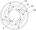
Fig. 3 is a schematic structural view of a toggle ring assembly of the present invention.
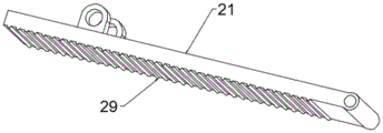
FIG. 4 is a schematic view of the structure of the clamping rod of the present invention.
Notations for reference numerals: the pile expanding device comprises a frame body 1, a lifting mechanism 2, a pile expanding guide cylinder 3, a mounting bracket 4, a connecting sleeve body 5, a universal connecting joint 7, a toggle ring assembly 8, a rotary hanger 9, a pile expanding motor 10, a lower bracket 11, an extrusion roller 12, an eccentric rotating shaft 13, a rotating gear 14, a transverse rack 15, an adjusting screw rod 16, an adjusting motor 17, a connecting rod 18, an inner ring body 19, an outer ring body 20, a clamping rod 21, a push-pull rod 22, a lifting screw rod 23, a lifting screw sleeve 24, a side reinforcing rod 25, a moving roller 26, a cylinder body 27, a stable bottom plate 28, a convex edge 29, an adjusting screw sleeve 30 and a clamping motor 31.
Detailed Description
The present invention will be described in detail with reference to the following embodiments, wherein like or similar elements are designated by like reference numerals throughout the several views, and wherein the shape, thickness or height of the various elements may be expanded or reduced in practice. The examples are given solely for the purpose of illustration and are not intended to limit the scope of the invention. Any obvious modifications or variations can be made to the present invention without departing from the spirit or scope of the present invention.
Example 1
Referring to fig. 1 to 3, in an embodiment of the present invention, a pile expanding apparatus for a bridge pile foundation includes a frame body 1 and a pile expanding guide cylinder 3, an elevating mechanism 2 is disposed at an upper end of the frame body 1, an installing support 4 whose position is adjusted by the elevating mechanism is disposed on the elevating mechanism 2, a connecting sleeve 5 sleeved on a middle side wall of the pile expanding guide cylinder 3 is disposed on a middle side wall of the pile expanding guide cylinder 3, a lower arm end of the installing support 4 is connected to a side wall of the connecting sleeve 5 through a universal joint 7, a toggle ring assembly 8 sleeved outside the pile expanding guide cylinder 3 is disposed at an upper end of the pile expanding guide cylinder 3, a rotating hanger 9 and a pile expanding motor 10 are disposed at a top end of the installing support 4, a top end of the rotating hanger 9 is connected to an output end of the pile expanding motor 10, a bottom of the rotating hanger 9 is connected to a side wall of the toggle ring assembly 8, an eccentric rotating shaft 13 and a lower support 11 are disposed at a bottom end of The side part of the lower support 11 is fixedly connected with the side part of the eccentric rotating shaft 13 through a connecting rod 18, and an adjusting and stirring component for stirring the eccentric rotating shaft 13 to rotate and adjusting the position of the lower support 11 is arranged in the pile-expanding guide cylinder 3;
when in use, the lifting mechanism is utilized to drive the mounting bracket 4 to move downwards so that the pile expanding guide cylinder 3 extends into the pile foundation hole, after the bottom of the pile expanding guide barrel 3 contacts the bottom of the pile foundation hole, the pile expanding guide barrel 3 can be driven to rotate by adjusting the toggle assembly, the pile expanding guide barrel 3 rotates to drive the pile expanding guide barrel 3 to rotate around the axis of the pile expanding guide barrel 3, so that the extrusion roller can move to the outer side of the bottom of the pile expanding guide barrel 3, thereby extruding the soil on the sidewall of the bottom of the pile foundation hole to the side to increase the bottom space, simultaneously driving the rotary hanger 9 to rotate by the pile expanding motor 10, driving the toggle ring assembly 8 to rotate by the rotary hanger 9, and utilizing the connection between the pile expanding guide barrel 3 and the universal joint 7 to toggle the pile expanding guide barrel 3 to rotate around the center of the rotary hanger 9, the bottom of the pile-expanding guide cylinder 3 can extrude the soil wall outwards again to increase the space, and the soil is extruded to increase the compactness of the soil on the inner wall of the hole so as to increase the firmness of the pile body;
the lifting mechanism comprises a lifting screw rod 23 arranged on the lifting mechanism 2 and two lifting screw sleeves 24 spirally sleeved on the lifting screw rod 23, the lifting screw rod 23 is driven by a motor to rotate, the side parts of the two lifting screw sleeves 24 are connected with the support arm of the lifting mechanism 2 in a sliding manner through a guide rail, the side parts of the two lifting screw sleeves 24 are fixedly connected with the mounting bracket 4, the lifting screw rod 23 is driven by the motor to rotate, and the mounting bracket 4 can be driven to lift by utilizing the spiral matching of the lifting screw rod 23 and the lifting screw sleeves 24 so that the pile extension guide barrel 3 can extend into a pile foundation hole;
the adjusting and shifting assembly comprises an adjusting screw rod 16, an adjusting motor 17 and a rotating gear 14 which are arranged inside the pile expanding guide barrel 3, the adjusting screw rod 16 is rotatably connected with the side wall inside the pile expanding guide barrel 3 and driven to rotate by the adjusting motor 17, an adjusting threaded sleeve 30 which is in threaded fit with the adjusting screw rod 16 is arranged on the adjusting screw rod 16, the side part of the adjusting threaded sleeve 30 is fixedly connected with a transverse rack 15 which slides on the bottom wall of the pile expanding guide barrel 3, the rotating gear 14 is arranged on the eccentric rotating shaft 13 and meshed with the transverse rack 15, the adjusting screw rod 16 is driven to rotate by the adjusting motor 17 to drive the adjusting threaded sleeve 30 to move on the adjusting threaded sleeve, so that the eccentric rotating shaft 13 rotates by the meshing of the transverse rack 15 and the rotating gear 14, and the stable state of the eccentric rotating shaft 13 is kept when the adjusting;
still be provided with a plurality of side anchor bars 25 on the frame body 1, the both ends of side anchor bar 25 respectively with 2 lateral parts of elevating system and 1 up end fixed connection of frame body, the stability of 2 installations of multiplicable elevating system of setting up of side anchor bar 25, 1 bottom four corners department of frame body all is provided with removal gyro wheel 26 and frame body 1 middle part is provided with cylinder block 27, cylinder block 27 bottom is provided with stabilizer blade 28, removes the setting of gyro wheel 26 and is convenient for support the device's removal, and cylinder block 27 flexible can make stabilizer blade 28 contact ground and guide the supporting role to make whole device remain stable state when the construction.
Example 2
Referring to fig. 1 and 4, the embodiment of the present invention is different from embodiment 1 in that: the toggle ring assembly 8 comprises an outer ring body 20 and an inner ring body 19, the inner ring body 19 is fixed on the rotary hanging bracket 9, the outer ring body 20 is rotatably installed on the rotary hanging bracket 9 and is driven to rotate by a clamping motor 31 arranged on the rotary hanging bracket 9, a plurality of clamping rods 21 with one ends hinged with the inner ring body are arranged on the inner wall of the inner ring body 19, a push-pull rod 22 with the end part hinged with the side edge of each clamping rod 21 is arranged on the side part of each clamping rod 21, and the other end of each push-pull rod 22 is hinged with the inner wall of the outer; the clamping motor 31 is used for driving the outer ring body 20 to rotate, the outer ring body 20 rotates to drive one end of the push-pull rod 22 to rotate, so that the clamping rods 21 are pushed to rotate around one end of the push-pull rod, the pile expanding guide barrel 3 can be clamped by the clamping rods 21 to be kept stable when the pile expanding guide barrel 3 extends into a pile foundation hole, and the pile expanding guide barrel 3 is loosened when the pile expanding guide barrel 3 rotates so that the pile expanding guide barrel 3 can rotate around the axis of the rotating hanging bracket 9 conveniently; the inner wall of the gripping rod 21 is provided with a plurality of ribs 29 to increase the friction force with the outer wall of the pile expanding guide 3 and improve the gripping force.
The above description is only for the specific embodiments of the present disclosure, but the scope of the present disclosure is not limited thereto, and any person skilled in the art can easily conceive of the changes or substitutions within the technical scope of the present disclosure, and all the changes or substitutions should be covered within the scope of the present disclosure. Therefore, the protection scope of the present disclosure shall be subject to the protection scope of the claims.
Claims (6)
1. Pile expanding equipment for bridge pile foundation, which comprises a frame body (1) and a pile expanding guide cylinder (3), wherein the upper end part of the frame body (1) is provided with a lifting mechanism (2), the lifting mechanism (2) is provided with a mounting bracket (4) the position of which is adjusted by the lifting mechanism, the pile expanding guide cylinder is characterized in that the side wall of the middle part of the pile expanding guide cylinder (3) is provided with a connecting sleeve body (5) sleeved on the side wall of the connecting sleeve body (5) through a universal connecting joint (7), the end part of the lower arm of the mounting bracket (4) is connected with the side wall of the connecting sleeve body (5), the upper end part of the pile expanding guide cylinder (3) is provided with a toggle ring assembly (8) sleeved outside the pile expanding guide cylinder, the top part of the mounting bracket (4) is provided with a rotary hanger (9) and a pile expanding motor (10), the top part of the rotary hanger (9) is connected with, an eccentric rotating shaft (13) and a lower support (11) are arranged at the bottom end part of the pile expanding guide cylinder (3), the eccentric rotating shaft (13) is rotatably arranged on the pile expanding guide cylinder (3), an extrusion roller (12) with the end part in rotating fit with the eccentric rotating shaft is arranged on the lower support (11), the side part of the lower support (11) is fixedly connected with the side part of the eccentric rotating shaft (13) through a connecting rod (18), an adjusting and shifting assembly for shifting the eccentric rotating shaft (13) to rotate and adjusting the position of the lower support (11) is arranged in the pile expanding guide cylinder (3), the shifting ring assembly (8) comprises an outer ring body (20) and an inner ring body (19), the inner ring body (19) is fixed on a rotating hanging bracket (9), the outer ring body (20) is rotatably arranged on the rotating hanging bracket (9) and is driven to rotate by a clamping motor (31) arranged on the rotating hanging bracket (9), and a plurality of clamping rods (21) with one end hinged with the inner ring body (, the side part of each clamping rod (21) is provided with a push-pull rod (22) with the end part hinged with the clamping rod, and the other end of the push-pull rod (22) is hinged with the inner wall of the outer ring body (20).
2. Pile extension equipment for bridge pile foundations according to claim 1, wherein the lifting mechanism comprises a lifting screw (23) arranged on the lifting mechanism (2) and two lifting screw sleeves (24) spirally sleeved on the lifting screw (23), the lifting screw (23) is driven to rotate by a motor, the side parts of the two lifting screw sleeves (24) are slidably connected with the support arm of the lifting mechanism (2) through a guide rail, and the side parts of the two lifting screw sleeves (24) are fixedly connected with the mounting bracket (4).
3. The pile expanding equipment for the bridge pile foundation is characterized in that the adjusting and stirring assembly comprises an adjusting screw rod (16), an adjusting motor (17) and a rotating gear (14) which are arranged inside the pile expanding guide barrel (3), the adjusting screw rod (16) is rotatably connected with the inner side wall of the pile expanding guide barrel (3) and the adjusting motor (17) drives the adjusting screw rod (16) to rotate, an adjusting screw sleeve (30) in screw fit with the adjusting screw rod (16) is arranged on the adjusting screw rod (16), the side part of the adjusting screw sleeve (30) is fixedly connected with a transverse rack (15) which slides on the bottom wall of the pile expanding guide barrel (3), and the rotating gear (14) is arranged on the eccentric rotating shaft (13) and is meshed with the transverse rack (15).
4. The pile expanding equipment for the bridge pile foundation according to claim 1, wherein the frame body (1) is further provided with a plurality of side reinforcing rods (25), and two ends of each side reinforcing rod (25) are fixedly connected with the side part of the lifting mechanism (2) and the upper end face of the frame body (1) respectively.
5. Pile extension equipment for bridge pile foundations according to claim 1, characterized in that the frame body (1) is provided with moving rollers (26) at the four corners of the bottom and a cylinder block (27) in the middle of the frame body (1), and a stabilizing bottom plate (28) is provided at the bottom of the cylinder block (27).
6. Pile expanding apparatus for bridge pile foundations according to claim 5, characterized in that the inner walls of the gripping rods (21) are provided with a plurality of ribs (29).
Priority Applications (1)
| Application Number | Priority Date | Filing Date | Title |
|---|---|---|---|
| CN202011124270.5A CN112196469B (en) | 2020-10-20 | 2020-10-20 | Pile expanding equipment for bridge pile foundation |
Applications Claiming Priority (1)
| Application Number | Priority Date | Filing Date | Title |
|---|---|---|---|
| CN202011124270.5A CN112196469B (en) | 2020-10-20 | 2020-10-20 | Pile expanding equipment for bridge pile foundation |
Publications (2)
| Publication Number | Publication Date |
|---|---|
| CN112196469A CN112196469A (en) | 2021-01-08 |
| CN112196469B true CN112196469B (en) | 2021-07-13 |
Family
ID=74009462
Family Applications (1)
| Application Number | Title | Priority Date | Filing Date |
|---|---|---|---|
| CN202011124270.5A Active CN112196469B (en) | 2020-10-20 | 2020-10-20 | Pile expanding equipment for bridge pile foundation |
Country Status (1)
| Country | Link |
|---|---|
| CN (1) | CN112196469B (en) |
Families Citing this family (2)
| Publication number | Priority date | Publication date | Assignee | Title |
|---|---|---|---|---|
| CN113513256B (en) * | 2021-03-15 | 2023-03-28 | 汪德旺 | Pile expanding equipment for road and bridge engineering |
| CN114808918B (en) * | 2022-03-11 | 2023-12-22 | 中电建路桥集团有限公司 | Construction method of gravel pile foundation in collapsible loess area |
Family Cites Families (8)
| Publication number | Priority date | Publication date | Assignee | Title |
|---|---|---|---|---|
| SU1579969A1 (en) * | 1988-02-11 | 1990-07-23 | Центральный научно-исследовательский и проектно-экспериментальный институт промышленных зданий и сооружений | Device for making borehole with spread under pile support |
| JP2000282773A (en) * | 1999-03-29 | 2000-10-10 | Kawasaki Steel Corp | Enlarged head for drilling method |
| CN201347552Y (en) * | 2009-01-05 | 2009-11-18 | 沧州市机械施工有限公司 | Multifunctional pile punching and expanding machine |
| CN109056726B (en) * | 2017-03-08 | 2021-01-22 | 林裕光 | Pile expanding equipment for municipal road and bridge engineering |
| CN108086910A (en) * | 2018-01-18 | 2018-05-29 | 北京地矿工程建设有限责任公司 | Long spire extruded and extended pile drilling machine boring method and long spire extruded and extended pile drilling machine |
| CN108589713A (en) * | 2018-05-08 | 2018-09-28 | 新河县双兴桩工机械有限公司 | Rammed bulb pile Immersed tunnel device |
| CN210562174U (en) * | 2019-04-19 | 2020-05-19 | 襄阳职业技术学院 | Civil engineering is with pile device |
| CN110106879B (en) * | 2019-05-16 | 2021-04-13 | 陈艳龙 | High-applicability multidimensional scaling and pile expanding equipment for road and bridge engineering |
-
2020
- 2020-10-20 CN CN202011124270.5A patent/CN112196469B/en active Active
Also Published As
| Publication number | Publication date |
|---|---|
| CN112196469A (en) | 2021-01-08 |
Similar Documents
| Publication | Publication Date | Title |
|---|---|---|
| CN112196469A (en) | Pile expanding equipment for bridge pile foundation | |
| CN222454379U (en) | Anti-rollover device for crane | |
| CN114182938B (en) | Section steel inclined column installation device and construction method thereof | |
| CN220747742U (en) | Temporary supporting device for building assembled wall | |
| CN218117299U (en) | Assembly type structure telescopic support frame for civil engineering | |
| CN109441102B (en) | A column formwork reinforcement frame structure | |
| CN114439252B (en) | Main arch supporting device for hoisting large-span steel structure roof | |
| CN212198351U (en) | Elevating gear for construction | |
| CN117702747B (en) | Pile extractor of anti-drop pile for constructional engineering | |
| CN218988567U (en) | Lifting hook device for hydraulic engineering tower crane | |
| CN220789427U (en) | Movable radius-changeable dismounting-free arch bridge bracket | |
| CN218708758U (en) | Tower crane bearing structure | |
| CN117905058A (en) | PHC pipe pile installation stabilizing device and PHC pipe pile installation stabilizing method | |
| CN212897705U (en) | Concrete engineering unilateral support | |
| CN213087523U (en) | Single-jack mechanism for fabricated building | |
| CN221027332U (en) | Complex interactive boulder stratum rotary digging pore-forming cast-in-place pile | |
| CN113404371A (en) | Self-adaptive telegraph pole installation auxiliary stabilizing system | |
| CN217999069U (en) | Pre-arranged beam supporting assembly for building engineering | |
| CN212027104U (en) | Civil engineering template bearing structure | |
| CN216587861U (en) | Building structure reinforcing apparatus | |
| CN219993063U (en) | An exterior wall waterproof construction device | |
| CN216042604U (en) | Fixing support for building engineering template | |
| CN221700974U (en) | Tower crane rotary platform | |
| CN223722401U (en) | Lifting type cable drum support frame | |
| CN221502718U (en) | Template supporting structure |
Legal Events
| Date | Code | Title | Description |
|---|---|---|---|
| PB01 | Publication | ||
| PB01 | Publication | ||
| SE01 | Entry into force of request for substantive examination | ||
| SE01 | Entry into force of request for substantive examination | ||
| GR01 | Patent grant | ||
| GR01 | Patent grant |