CN112193809A - Nondestructive feeding push plate structure for fragile powder forming part - Google Patents

Nondestructive feeding push plate structure for fragile powder forming part Download PDF

Info

Publication number
CN112193809A
CN112193809A CN202011227293.9A CN202011227293A CN112193809A CN 112193809 A CN112193809 A CN 112193809A CN 202011227293 A CN202011227293 A CN 202011227293A CN 112193809 A CN112193809 A CN 112193809A
Authority
CN
China
Prior art keywords
feeding
material loading
step motor
belt
baffle
Prior art date
Legal status (The legal status is an assumption and is not a legal conclusion. Google has not performed a legal analysis and makes no representation as to the accuracy of the status listed.)
Withdrawn
Application number
CN202011227293.9A
Other languages
Chinese (zh)
Inventor
谢纪东
刘晓春
包崇兵
易亮
Current Assignee (The listed assignees may be inaccurate. Google has not performed a legal analysis and makes no representation or warranty as to the accuracy of the list.)
Changsha Maijing Technology Co ltd
Original Assignee
Changsha Maijing Technology Co ltd
Priority date (The priority date is an assumption and is not a legal conclusion. Google has not performed a legal analysis and makes no representation as to the accuracy of the date listed.)
Filing date
Publication date
Application filed by Changsha Maijing Technology Co ltd filed Critical Changsha Maijing Technology Co ltd
Priority to CN202011227293.9A priority Critical patent/CN112193809A/en
Publication of CN112193809A publication Critical patent/CN112193809A/en
Withdrawn legal-status Critical Current

Links

Images

Classifications

    • B—PERFORMING OPERATIONS; TRANSPORTING
    • B65—CONVEYING; PACKING; STORING; HANDLING THIN OR FILAMENTARY MATERIAL
    • B65G—TRANSPORT OR STORAGE DEVICES, e.g. CONVEYORS FOR LOADING OR TIPPING, SHOP CONVEYOR SYSTEMS OR PNEUMATIC TUBE CONVEYORS
    • B65G47/00—Article or material-handling devices associated with conveyors; Methods employing such devices
    • B65G47/74—Feeding, transfer, or discharging devices of particular kinds or types
    • B65G47/82—Rotary or reciprocating members for direct action on articles or materials, e.g. pushers, rakes, shovels
    • B—PERFORMING OPERATIONS; TRANSPORTING
    • B65—CONVEYING; PACKING; STORING; HANDLING THIN OR FILAMENTARY MATERIAL
    • B65G—TRANSPORT OR STORAGE DEVICES, e.g. CONVEYORS FOR LOADING OR TIPPING, SHOP CONVEYOR SYSTEMS OR PNEUMATIC TUBE CONVEYORS
    • B65G23/00—Driving gear for endless conveyors; Belt- or chain-tensioning arrangements
    • B65G23/44—Belt or chain tensioning arrangements
    • B—PERFORMING OPERATIONS; TRANSPORTING
    • B65—CONVEYING; PACKING; STORING; HANDLING THIN OR FILAMENTARY MATERIAL
    • B65G—TRANSPORT OR STORAGE DEVICES, e.g. CONVEYORS FOR LOADING OR TIPPING, SHOP CONVEYOR SYSTEMS OR PNEUMATIC TUBE CONVEYORS
    • B65G47/00—Article or material-handling devices associated with conveyors; Methods employing such devices
    • B65G47/22—Devices influencing the relative position or the attitude of articles during transit by conveyors
    • B65G47/26—Devices influencing the relative position or the attitude of articles during transit by conveyors arranging the articles, e.g. varying spacing between individual articles
    • B—PERFORMING OPERATIONS; TRANSPORTING
    • B65—CONVEYING; PACKING; STORING; HANDLING THIN OR FILAMENTARY MATERIAL
    • B65G—TRANSPORT OR STORAGE DEVICES, e.g. CONVEYORS FOR LOADING OR TIPPING, SHOP CONVEYOR SYSTEMS OR PNEUMATIC TUBE CONVEYORS
    • B65G49/00—Conveying systems characterised by their application for specified purposes not otherwise provided for
    • B65G49/05—Conveying systems characterised by their application for specified purposes not otherwise provided for for fragile or damageable materials or articles

Landscapes

  • Engineering & Computer Science (AREA)
  • Mechanical Engineering (AREA)
  • Filling Or Emptying Of Bunkers, Hoppers, And Tanks (AREA)
  • Devices For Post-Treatments, Processing, Supply, Discharge, And Other Processes (AREA)

Abstract

本发明公开了一种易碎粉体成型件无损上料推板结构,第三步进电机通过同步带轮驱动件带动带挡条上料皮带旋转;下料中间滑板一端与第一上料顶升板连接,第一上料顶升板一侧设置有滑轨,第三上料固定板连接一侧可在滑轨上滑动,第二上料固定板一侧与第二上料顶升板一侧连接,第三上料固定板一侧与第二上料顶升板一侧连接,其中,第一上料顶升板、第二上料顶升板以及第三上料顶升板可活动,所述第一上料固定板、第二上料固定板和第三上料固定板固定。本发明中排序线中物料排序输送侧壁的宽度可以任意调节以兼容各式物料,排序线中包含有防止重叠料通过的结构,各送料部分的输送速度也可任意调节,由此保证送料过程稳定。

Figure 202011227293

The invention discloses a non-destructive feeding push plate structure for fragile powder forming parts. A third stepping motor drives a feeding belt with a retaining bar to rotate through a synchronous pulley driving part; The lifting plate is connected, one side of the first feeding lifting plate is provided with a sliding rail, the connecting side of the third feeding fixing plate can slide on the sliding rail, and one side of the second feeding fixing plate is connected with the second feeding lifting plate One side is connected, and one side of the third feeding fixing plate is connected with one side of the second feeding lifting plate, wherein the first feeding lifting plate, the second feeding lifting plate and the third feeding lifting plate can be The first feeding fixing plate, the second feeding fixing plate and the third feeding fixing plate are fixed. In the present invention, the width of the material sorting and conveying sidewall in the sorting line can be adjusted arbitrarily to be compatible with various materials. The sorting line includes a structure to prevent overlapping materials from passing through, and the conveying speed of each feeding part can also be adjusted arbitrarily, thereby ensuring the feeding process. Stablize.

Figure 202011227293

Description

Nondestructive feeding push plate structure for fragile powder forming part
Technical Field
The invention relates to the technical field of machining, in particular to a nondestructive feeding push plate structure for a fragile powder forming part.
Background
In the feeding process of the powder forming part with fragile texture, the defects of edge breakage, defect and the like are easily generated on the surface of a workpiece, and the surface of the workpiece is protected in the feeding process. Has an extremely important influence on the production cost and quality management of enterprises.
In a general feeding process, it is a common choice to feed workpieces by using a vibrating tray. The vibrating plate can accumulate materials in the feeding process, and the materials can vibrate in the accumulation process and the feeding process, so that the surface of the materials is easily damaged. Therefore, the product qualification rate is greatly reduced, great unnecessary material loss is brought to manufacturers, and great pressure is brought to quality control of products.
Disclosure of Invention
The invention aims to overcome the defects in the prior art and provides a nondestructive feeding push plate structure for fragile powder forming parts, wherein the width of a material sequencing conveying side wall in a sequencing line can be adjusted at will to be compatible with various materials, the sequencing line comprises a structure for preventing overlapped materials from passing through, and the conveying speed of each feeding part can be adjusted at will, so that the stability of the feeding process is ensured, and the problems in the background technology can be effectively solved.
In order to solve the technical problems, the invention provides the following technical scheme:
the invention provides a nondestructive feeding push plate structure for a fragile powder forming part, which comprises:
the feeding belt with the barrier strip is connected with the metal plate manufacturing hopper at one end;
the third step motor is arranged on one side of the feeding belt with the barrier strip and drives the feeding belt with the barrier strip to rotate through a synchronous belt wheel driving piece;
slide in the middle of the unloading, slide one end is connected with first material loading jacking board in the middle of the unloading, first material loading jacking board one side is provided with the slide rail, and third material loading fixed plate connects one side can slide on the slide rail, and second material loading fixed plate one side is connected with second material loading jacking board one side, third material loading fixed plate one side with second material loading jacking board one side is connected, second material loading fixed plate opposite side is connected with third material loading jacking board one side, third material loading jacking board opposite side is connected with first material loading fixed plate one side.
As an optimal scheme, breakable powder formed part is harmless material loading push pedal structure still includes the feeding transfer chain blend stop, the feeding transfer chain blend stop set up in take blend stop material loading belt both sides.
As an optimal scheme, breakable powder formed part is harmless material loading push pedal structure, still includes feed mechanism belt line curb plate, feed mechanism belt line curb plate set up in take blend stop feeding belt one side.
As an optimal scheme, breakable powder forming part is harmless material loading push pedal structure still includes first step motor, connecting rod, carousel and top shoe, first step motor one end with the carousel is connected, the carousel set up in top shoe one side, connecting rod one end with the output of first step motor is connected.
As an optimal scheme, fragile powder formed part is harmless material loading push pedal structure still includes fourth step motor, initiative cylinder, first gyro wheel, PE backup pad, DC brushless motor, unloading baffle, brush cylinder and second gyro wheel, PE backup pad one end with first gyro wheel is connected, PE backup pad bottom with fourth step motor with the initiative cylinder is connected, the PE backup pad with the unloading baffle is connected, DC brushless motor set up in unloading baffle one side, the second gyro wheel set up in DC brushless motor below, second gyro wheel one side is provided with the brush cylinder.
As an optimal scheme, breakable powder formed part is harmless material loading push pedal structure still includes second step motor, initiative cylinder, belt tensioning seat, first side baffle and second side baffle, the second step motor set up in first side baffle below, first side baffle with second side baffle is parallel to each other, second side baffle one end is provided with belt tensioning seat, belt tensioning seat is provided with two that are parallel to each other, initiative cylinder both ends respectively with belt tensioning seat is connected.
One or more technical schemes provided by the invention at least have the following technical effects or advantages:
1. the width of the material sequencing conveying side wall in the middle sequencing line can be adjusted at will to be compatible with various materials, the sequencing line comprises a structure for preventing overlapped materials from passing through, and the conveying speed of each feeding part can also be adjusted at will, so that the stability of the feeding process is ensured.
Drawings
The accompanying drawings, which are included to provide a further understanding of the invention and are incorporated in and constitute a part of this specification, illustrate embodiments of the invention and together with the description serve to explain the principles of the invention and not to limit the invention.
In the drawings:
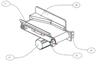
FIG. 1 is a schematic diagram of a material lifting line of a nondestructive feeding push plate structure of a fragile powder molding part in the embodiment of the invention.
Fig. 2 is a perspective view of a push plate structure in a material lifting line of a nondestructive feeding push plate structure of a fragile powder molding part in the embodiment of the invention.
Fig. 3 is a schematic diagram of a transmission structure of a driving push plate in a material lifting line of a nondestructive feeding push plate structure of a fragile powder molding part in the embodiment of the invention.
Fig. 4 is a perspective view of a sorting line structure of a nondestructive feeding push plate structure of a fragile powder molding member in the embodiment of the invention.
FIG. 5 is a perspective view of the other side of the sorting line of the nondestructive feeding push plate structure of the fragile powder molding member in the embodiment of the present invention.
Reference numbers in the figures: 1. a feeding belt with a barrier strip; 2. a feed conveying line barrier strip; 3. A feeding mechanism belt line side plate; 4. a metal plate hopper; 5. a stepping motor; 6. a synchronous pulley drive; 7. a blanking middle sliding plate; 8. a first loading jacking plate; 9. a second feeding jacking plate; 10. a third loading jacking plate; 11. a slide rail; 12. a first feeding fixing plate; 13. a second feeding fixing plate; 14. a third feeding fixing plate; 15. a first stepper motor; 16. a connecting rod; 17. a turntable; 18. an upper slide plate; 19. a stepping motor; 20. a driving roller; 21. a first roller; 22. a PE support plate; 23. a DC brushless motor; 24. a blanking baffle; 25. a brush roller; 26. a second roller; 27. a second stepping motor; 28. a driving roller; 29. a belt tensioning seat; 30. a first side baffle; 31. a second side barrier.
Detailed Description
In order to make the objects, technical solutions and advantages of the present invention more apparent, the present invention is described in further detail below with reference to the accompanying drawings and embodiments. It should be understood that the specific embodiments described herein are merely illustrative of the invention and are not intended to limit the invention.
It will be understood that when an element is referred to as being "secured to" or "disposed on" another element, it can be directly on the other element or be indirectly on the other element. When an element is referred to as being "connected to" another element, it can be directly connected to the other element or be indirectly connected to the other element.
In the description of the present invention, it is to be understood that the terms "length", "width", "upper", "lower", "front", "rear", "left", "right", "vertical", "horizontal", "top", "bottom", "inner", "outer", and the like, indicate orientations or positional relationships based on the orientations or positional relationships illustrated in the drawings, and are used merely for convenience in describing the present invention and for simplicity in description, and do not indicate or imply that the devices or elements referred to must have a particular orientation, be constructed in a particular orientation, and be operated, and thus, are not to be construed as limiting the present invention.
Furthermore, the terms "first", "second" and "first" are used for descriptive purposes only and are not to be construed as indicating or implying relative importance or implicitly indicating the number of technical features indicated. Thus, a feature defined as "first" or "second" may explicitly or implicitly include one or more of that feature. In the description of the present invention, "a plurality" means two or more unless specifically defined otherwise.
For better understanding of the above technical solutions, the following detailed descriptions will be provided in conjunction with the drawings and the detailed description of the present invention.
Example (b):
referring to fig. 1-5, the present embodiment provides a nondestructive feeding push plate structure for a fragile powder molding member, including:
the device comprises a feeding belt 1 with a barrier strip, wherein one end of the feeding belt 1 with the barrier strip is connected with a metal plate manufacturing hopper 4;
a third step motor 5, wherein the third step motor 5 is arranged on one side of the feeding belt 1 with the barrier strip, and the third step motor 5 drives the feeding belt 1 with the barrier strip to rotate through a synchronous belt wheel driving piece 6;
slide 7 in the middle of the unloading, 7 one end of slide is connected with first material loading jacking board 8 in the middle of the unloading, 8 one side of first material loading jacking board is provided with slide rail 11, and third material loading fixed plate 14 is connected one side can slide on the slide rail 11, and second material loading fixed plate 13 one side is connected with second material loading jacking board 9 one side, third material loading fixed plate 14 one side with second material loading jacking board 9 one side is connected, second material loading fixed plate 13 opposite side is connected with third material loading jacking board 10 one side, third material loading jacking board 10 opposite side is connected with first material loading fixed plate 12 one side.
As an optimal scheme, breakable powder formed part is harmless material loading push pedal structure still includes feeding transfer chain blend stop 2, feeding transfer chain blend stop 2 set up in take 1 both sides of blend stop material loading belt.
As an optimal scheme, breakable powder formed part is harmless material loading push pedal structure, still includes feed mechanism belt line curb plate 3, feed mechanism belt line curb plate 3 set up in take 1 one side of blend stop feeding belt.
As a preferred scheme, breakable powder forming part is harmless material loading push pedal structure still includes first step motor 15, connecting rod 16, carousel 17 and upper slide 18, first step motor 15 one end with carousel 17 is connected, carousel 17 set up in upper slide 18 one side, connecting rod 16 one end with the output of first step motor 15 is connected.
As a preferred scheme, breakable powder forming part is harmless to be loaded in push pedal structure, still includes fourth step motor 19, initiative cylinder 20, first gyro wheel 21, PE backup pad 22, direct current brushless motor 23, unloading baffle 24, brush roller 25 and second gyro wheel 26, PE backup pad 22 one end with first gyro wheel 21 is connected, PE backup pad 22 bottom with fourth step motor 19 with initiative cylinder 20 is connected, PE backup pad 22 with unloading baffle 24 is connected, direct current brushless motor 23 set up in unloading baffle 24 one side, second gyro wheel 26 set up in direct current brushless motor 23 below, second gyro wheel 26 one side is provided with brush roller 25.
As a preferred scheme, breakable powder formed part is harmless material loading push pedal structure still includes second step motor 27, initiative cylinder 28, belt tensioning seat 29, first side baffle 30 and second side baffle 31, second step motor 27 set up in first side baffle 30 below, first side baffle 30 with second side baffle 31 is parallel to each other, second side baffle 31 one end is provided with belt tensioning seat 29, belt tensioning seat 29 is provided with two that are parallel to each other, initiative cylinder 28 both ends respectively with belt tensioning seat 29 connects.
Finally, it should be noted that: although the present invention has been described in detail with reference to the foregoing embodiments, it will be apparent to those skilled in the art that changes may be made in the embodiments and/or equivalents thereof without departing from the spirit and scope of the invention. Any modification, equivalent replacement, or improvement made within the spirit and principle of the present invention should be included in the protection scope of the present invention.

Claims (6)

1. The utility model provides a breakable powder formed part is harmless material loading push pedal structure which characterized in that: the method comprises the following steps:
the device comprises a feeding belt (1) with a barrier strip, wherein one end of the feeding belt (1) with the barrier strip is connected with a sheet metal material making hopper (4);
the third step motor (5), the third step motor (5) is arranged on one side of the feeding belt (1) with the barrier strip, and the third step motor (5) drives the feeding belt (1) with the barrier strip to rotate through a synchronous pulley driving piece (6);
slide (7) in the middle of the unloading, slide (7) one end is connected with first material loading jacking board (8) in the middle of the unloading, first material loading jacking board (8) one side is provided with slide rail (11), third material loading fixed plate (14) are connected one side and can slide on slide rail (11), second material loading fixed plate (13) one side is connected with second material loading jacking board (9) one side, third material loading fixed plate (14) one side is connected with second material loading jacking board (9) one side, second material loading fixed plate (13) opposite side is connected with third material loading jacking board (10) one side, third material loading jacking board (10) opposite side is connected with first material loading fixed plate (12) one side.
2. The lossless feeding push plate structure for the fragile powder forming part according to claim 1, wherein: still include feeding transfer chain blend stop (2), feeding transfer chain blend stop (2) set up in take blend stop feeding belt (1) both sides.
3. The lossless feeding push plate structure for the fragile powder forming part according to claim 2, wherein: still include feed mechanism belt line curb plate (3), feed mechanism belt line curb plate (3) set up in take blend stop feeding belt (1) one side.
4. The lossless feeding push plate structure for the fragile powder forming part according to claim 3, wherein: still include first step motor (15), connecting rod (16), carousel (17) and top slide (18), first step motor (15) one end is connected with carousel (17), and carousel (17) set up in top slide (18) one side, and connecting rod (16) one end is connected with the output of first step motor (15).
5. The lossless feeding push plate structure for the fragile powder forming part according to claim 4, wherein: still include fourth step motor (19), driving roll (20), first gyro wheel (21), PE backup pad (22), DC brushless motor (23), unloading baffle (24), brush cylinder (25) and second gyro wheel (26), PE backup pad (22) one end is connected with first gyro wheel (21), PE backup pad (22) bottom is connected with fourth step motor (19) and driving roll (20), PE backup pad (22) are connected with unloading baffle (24), and DC brushless motor (23) set up in unloading baffle (24) one side, second gyro wheel (26) set up in DC brushless motor (23) below, second gyro wheel (26) one side is provided with brush cylinder (25).
6. The lossless feeding push plate structure for the fragile powder forming part according to claim 5, wherein: still include second step motor (27), driving roll (28), belt tensioning seat (29), first side baffle (30) and second side baffle (31), second step motor (27) set up in first side baffle (30) below, first side baffle (30) are parallel to each other with second side baffle (31), second side baffle (31) one end is provided with belt tensioning seat (29), belt tensioning seat (29) are provided with two that are parallel to each other, driving roll (28) both ends are connected with belt tensioning seat (29) respectively.
CN202011227293.9A 2020-11-06 2020-11-06 Nondestructive feeding push plate structure for fragile powder forming part Withdrawn CN112193809A (en)

Priority Applications (1)

Application Number Priority Date Filing Date Title
CN202011227293.9A CN112193809A (en) 2020-11-06 2020-11-06 Nondestructive feeding push plate structure for fragile powder forming part

Applications Claiming Priority (1)

Application Number Priority Date Filing Date Title
CN202011227293.9A CN112193809A (en) 2020-11-06 2020-11-06 Nondestructive feeding push plate structure for fragile powder forming part

Publications (1)

Publication Number Publication Date
CN112193809A true CN112193809A (en) 2021-01-08

Family

ID=74033371

Family Applications (1)

Application Number Title Priority Date Filing Date
CN202011227293.9A Withdrawn CN112193809A (en) 2020-11-06 2020-11-06 Nondestructive feeding push plate structure for fragile powder forming part

Country Status (1)

Country Link
CN (1) CN112193809A (en)

Citations (3)

* Cited by examiner, † Cited by third party
Publication number Priority date Publication date Assignee Title
CN202542424U (en) * 2012-04-01 2012-11-21 浙江东明不锈钢制品股份有限公司 Automatic feeding mechanism for threaded rod
CN210914197U (en) * 2019-10-31 2020-07-03 苏州苏恩自动化设备有限公司 Feeding device for shaft parts
CN211812038U (en) * 2020-01-17 2020-10-30 湖北江一特智能科技有限公司 Automatic feeding device for spring conveying

Patent Citations (3)

* Cited by examiner, † Cited by third party
Publication number Priority date Publication date Assignee Title
CN202542424U (en) * 2012-04-01 2012-11-21 浙江东明不锈钢制品股份有限公司 Automatic feeding mechanism for threaded rod
CN210914197U (en) * 2019-10-31 2020-07-03 苏州苏恩自动化设备有限公司 Feeding device for shaft parts
CN211812038U (en) * 2020-01-17 2020-10-30 湖北江一特智能科技有限公司 Automatic feeding device for spring conveying

Similar Documents

Publication Publication Date Title
CN217477651U (en) Automatic turning device of section of thick bamboo yarn
JP2003171022A (en) Paper feeder
CN214055567U (en) Mylar die-cutting machine structure
KR100256222B1 (en) Marking device for manufacturing semiconductor packages
WO2024193376A1 (en) Conveying device
CN117002789B (en) Automatic food boxing machine
JP5838128B2 (en) Transport device
CN219535149U (en) Product stitch forming and processing production line
JP3666706B2 (en) Tire transport type sorting device
CN116207583A (en) Product stitch forming and processing production line
JP2000118755A (en) Paper feeder
US11529821B2 (en) Book block feed device
JP2914541B2 (en) Panel automatic loading device
CN204568729U (en) A kind of feed system of product examine machine
JP2000229726A (en) Article transfer device
CN112549165A (en) Mylar die-cutting machine structure
CN217416257U (en) Material marshalling device
CN224029350U (en) Packing device and packing equipment
CN223221983U (en) Flat battery sorting and conveying device
CN223322350U (en) A material belt feeding mechanism and a material belt disassembling and splicing integrated machine
JP2005298104A (en) Carrying installation
CN222081786U (en) Auto parts conveyor
CN219278580U (en) Push rod vibrating plate feeding mechanism
KR200340664Y1 (en) Apparatus for automatically loading corrugated sheets
CN121590845A (en) Labeling system

Legal Events

Date Code Title Description
PB01 Publication
PB01 Publication
SE01 Entry into force of request for substantive examination
CB02 Change of applicant information

Address after: 410000 room 249, building 1, R & D headquarters, Science Park, Central South University, changzuo Road, Yuelu street, Yuelu District, Changsha City, Hunan Province

Applicant after: Changsha Maijing Technology Co.,Ltd.

Address before: 410000 room 249, building 1, R & D headquarters, Science Park, Central South University, changzuo Road, Yuelu street, Yuelu District, Changsha City, Hunan Province

Applicant before: Changsha Maijing Technology Co.,Ltd.

CB02 Change of applicant information
CB03 Change of inventor or designer information

Inventor after: Xie Jidong

Inventor after: Bao Chongbing

Inventor after: Yi Liang

Inventor before: Xie Jidong

Inventor before: Liu Xiaochun

Inventor before: Bao Chongbing

Inventor before: Yi Liang

CB03 Change of inventor or designer information
WW01 Invention patent application withdrawn after publication

Application publication date: 20210108

WW01 Invention patent application withdrawn after publication