Novel aluminum profile cutting device and cutting method thereof
Technical Field
The invention relates to the field of aluminum profile processing, in particular to a novel aluminum profile cutting device and a novel aluminum profile cutting method.
Background
With the rapid advance of large-scale capital construction investment and industrialization process in China, the yield and consumption of the whole industry of aluminum profiles are rapidly increased, and China also becomes the biggest aluminum profile production base and consumption market in the world. Through the high-speed growth of nearly 10 years, the aluminum profile industry in China steps into a new development stage and shows a plurality of new development trends. The density of the aluminium profiles is about one third of the density of steel, copper or brass. And under most environmental conditions, including air, water (or brine), petrochemistry and many chemical systems, aluminum can exhibit excellent corrosion resistance, so the use of aluminum profiles can better meet the actual demands of construction, while in electrical conductivity, aluminum profiles are often selected for their excellent electrical conductivity, which is approximately one-half of that of copper on a weight-equal basis. Aluminum profiles are non-ferromagnetic, which is an important property for the electrical and electronics industries. Aluminum profiles are not self-flammable, which is important for applications involving handling or contact with flammable and explosive materials. The aluminum has extremely high recoverability, and the characteristics of the secondary aluminum are hardly different from those of the primary aluminum. In conclusion, the application market of the aluminum profile is continuously increased, and the yield and the demand are increased year by year.
In the use of aluminium alloy, inevitable needs carry out quantitative cutting to the aluminium alloy, just so can be better carry out the use of aluminium alloy in practical application. The existing common aluminum profile cutting mode mainly comprises the step of manually operating a cutting machine for cutting, the cutting machine is generally a small-sized cutting machine, and the cutting machine cannot effectively clamp and fix an aluminum profile in the use process, so that the aluminum profile is easy to shake in the cutting process, the cutting precision of the aluminum profile is directly influenced, and the subsequent use of the aluminum profile is influenced; simultaneously, current aluminium alloy cutting device lacks necessary cleaning device, leads to the piece that produces in the aluminium alloy cutting process to splash everywhere, not only can harm operating personnel's healthy, and can cause certain pollution to the construction environment, is unfavorable for the processing of aluminium alloy to use.
Therefore, there is a need to provide a novel aluminum profile cutting device and a cutting method thereof to solve the above technical problems.
Disclosure of Invention
The invention provides a novel aluminum profile cutting device and a novel aluminum profile cutting method.
In order to solve the technical problems, the novel aluminum profile cutting device provided by the invention comprises a scrap collecting mechanism, wherein a clamping and fixing mechanism is fixed right above the scrap collecting mechanism, and a cutting mechanism is fixed right above the clamping and fixing mechanism; the clamping and fixing mechanism comprises a group of first supporting plates, a group of second gears and a group of second handles, wherein one surface of each first supporting plate is rotatably connected with a first gear through a bearing, the other end of each first gear is fixedly provided with a connecting rod, the other end of each connecting rod is fixedly provided with a first handle, the two second gears are both meshed with the first handles, a group of axially symmetrically distributed sliding rails and a group of axially symmetrically distributed first fixing plates are fixed between the two first supporting plates, the sliding rails on the same side are fixedly connected with the first fixing plates, the sliding rails are provided with first sliding chutes, one end of each second gear penetrates through one surface of one first supporting plate and is fixedly provided with a first threaded screw rod, the other surface of the other first supporting plate is rotatably connected with another group of first threaded screw rods through a bearing, one ends of the two correspondingly arranged first threaded screw rods are fixedly connected, and the inner walls of the first sliding chutes are in sliding fit with a group of, two the slider is located two first screw lead screws respectively, it has first screw hole to open on the slider, the slider is through first screw hole and first screw lead screw threaded connection, a slider fixed surface has splint, one it has the second spout to open on the first fixed plate, second spout one end inner wall is fixed with the fixed block, a second handle fixed surface has second screw lead screw, the second screw lead screw other end runs through the fixed block and rotates through a bearing and a second spout inner wall and be connected, second spout inner wall sliding fit has the stopper, it has the second screw hole to open on the stopper, the stopper passes through second screw hole and second screw lead screw threaded connection, it is equipped with the calibrated scale to be close to second spout edge on the first fixed plate.
Preferably, it cuts the groove to open on the first backup pad, two the slide rail is about two vertical plane symmetric distributions that cut groove place, first gear all is located same vertical plane with cutting the groove.
Preferably, the rotation directions of the two first threaded screw rods on the second gear are opposite, the cross section of the first sliding groove and the cross section of the sliding block are both of a T-shaped structure, a through hole is formed in the bottom of the sliding rail and is communicated with the first sliding groove, and the two sliding blocks in the first sliding groove are symmetrically distributed about a vertical plane where the second sliding groove is located.
Preferably, the debris collection mechanism comprises a bottom plate and a dust collection hopper, a group of second support plates are fixed on one surface of the bottom plate, and the tops of the second support plates are fixedly connected with the bottoms of the first support plates.
Preferably, a group of dust collecting boxes is fixed on the surface of the bottom plate, a material taking groove is formed in the surface of the dust collecting box, a box door is rotatably connected to the surface of the dust collecting box through hinges, the box door is in clearance fit with the inner wall of the material taking groove, a lock catch is fixed on the surface of the box door, the box door is fixedly connected with the surface of the dust collecting box through the lock catch, and a baffle is fixed at the bottom of the dust collecting hopper.
Preferably, a first air delivery pipe penetrates through and is fixed on the other surface of the dust collection box, a three-way pipe is fixedly communicated between the two first air delivery pipes, one end of the three-way pipe is fixedly communicated with a second air delivery pipe, the other end of the second air delivery pipe penetrates through the baffle and extends into the dust collection hopper, and the second air delivery pipe is fixedly connected with the baffle.
Preferably, a blower is fixed on one surface of the dust collection box, an air inlet pipe is fixed at one end of an air inlet of the blower, and a filter screen is fixed at the other end of the air inlet pipe and penetrates through one surface of the dust collection box.
Preferably, cutting mechanism includes the third backup pad, a third backup pad surface and a first backup pad fixed surface are connected, open at third backup pad top has a set of mounting groove, the mounting groove inner wall is fixed with first pneumatic cylinder, two first pneumatic cylinder other end is fixed with the second fixed plate.
Preferably, a third fixing plate is fixed on one surface of the second fixing plate, the cross section of the third fixing plate is of an L-shaped structure, a group of sliding rods are fixed between the second fixing plate and the third fixing plate, a second hydraulic cylinder is fixed on one surface of the second fixing plate, the other end of the second hydraulic cylinder is fixed with a connecting block, a group of third sliding grooves are formed in the connecting block, the sliding rods are in clearance fit with the inner walls of the third sliding grooves, a motor is fixed at the bottom of the connecting block, and a blade is fixed at one end of an output shaft of the motor.
The cutting method of the novel aluminum profile cutting device comprises the following steps:
SS01, limiting the length of the aluminum profile to be cut: firstly, rotating a second handle to enable the second handle to drive a second threaded screw rod to rotate, adjusting the position of a limiting block in a screw rod transmission mode, and adjusting the limiting block to move to a specified position by referring to a dial arranged at the edge of a second sliding groove in a first fixing plate so that the distance from the limiting block to the position right below a blade just meets the actual requirement of the cutting length of the aluminum profile;
SS02, clamping and fixing the aluminum profile to be cut: taking out an aluminum profile to be cut, placing the aluminum profile between the two groups of clamping plates, enabling one end of the aluminum profile to be tightly attached to the limiting block, rotating the first handle to enable the first handle to drive the first gear to rotate, and driving the two first threaded screw rods on the second gear to rotate in a gear meshing mode, wherein the rotating directions of the two first threaded screw rods are opposite, so that the two sliding blocks on the two first threaded screw rods can be drawn close to the middle in a screw rod transmission mode, and the aluminum profile placed in the middle is clamped and fixed;
SS03, cutting of aluminum profiles: firstly, starting a motor to drive a blade to rotate, then starting a group of first hydraulic cylinders to enable the first hydraulic cylinders to drive the blade to move downwards, then starting a second hydraulic cylinder to operate to enable the second hydraulic cylinder to push the blade to complete cutting of the aluminum profile, powering off the motor after the cutting is completed, starting a group of first hydraulic cylinders to drive the blade to move upwards to an original height, and then starting a second hydraulic cylinder to drive the blade to return to an initial position, thereby completing cutting processing of the aluminum profile;
SS04, collection of debris: in step SS03, the motor is started and a set of blowers are operated to make the blowers generate a downward suction force to suck the chips generated by cutting the aluminum profiles into the dust hoppers and finally guide the chips into the dust box for collection and storage, and meanwhile, after the aluminum profiles are cut by the blades and return to the initial position, the set of blowers is closed again, the box door is opened periodically to complete the cleaning of the chips in the dust box, namely the collection of the chips in the aluminum profile cutting process is completed.
Compared with the prior art, the novel aluminum profile cutting device and the cutting method thereof provided by the invention have the following beneficial effects:
1. according to the aluminum profile cutting device, the limit block can effectively adjust the length to be cut of the aluminum profile in a screw rod transmission mode through the scales arranged on the edge of the second sliding groove, and can effectively and accurately fix the aluminum profile to be cut under the combined action of the two groups of clamping plates, so that the aluminum profile is higher in cutting efficiency, higher in cutting accuracy and more convenient and labor-saving in the cutting process, and the cutting requirement of the aluminum profile in actual use is better met.
2. According to the aluminum profile clamping device, the position of the blade can be effectively adjusted through the mutual matching of the group of the first hydraulic cylinder and the second hydraulic cylinder, the aluminum profile can be effectively cut, the blade is prevented from accidentally injuring an operator when the clamping fixing mechanism clamps the aluminum profile, and the aluminum profile is clamped more safely and conveniently.
3. According to the invention, through the operation of the group of blowers, the scraps generated when the cutting mechanism cuts the aluminum profile can be quickly and effectively sucked into the dust collecting hopper and finally sucked into the group of dust collecting boxes to be stored, so that the cleanness of the aluminum profile cutting environment is ensured, meanwhile, the interference of the aluminum profile cutting scraps on operators is avoided, the health of the operators is ensured, the labor consumption required by the cleanness of the aluminum profile processing environment is reduced due to the arrangement of the scrap collecting mechanism, and the actual requirements of the aluminum profile cutting production are better met.
Drawings
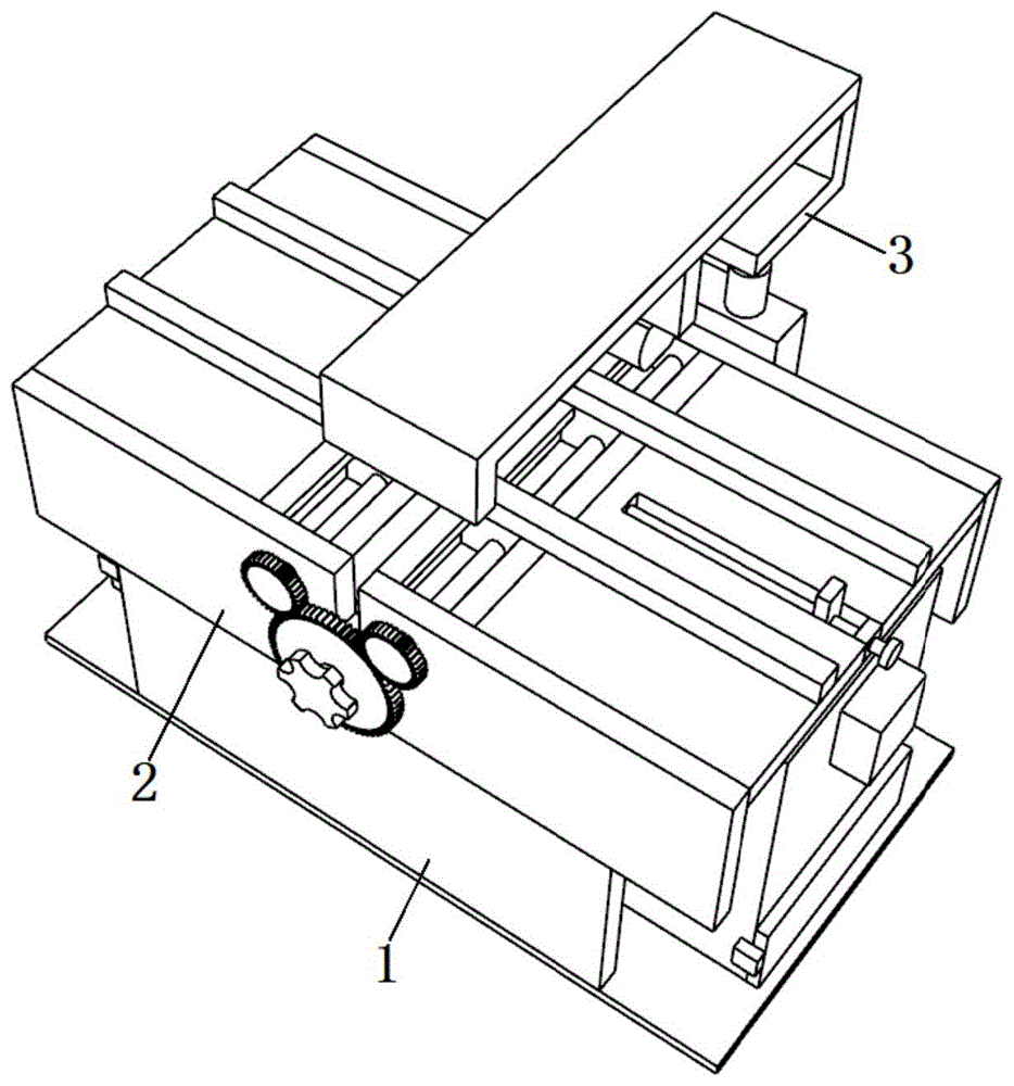
Fig. 1 is a schematic structural diagram of a preferred embodiment of a novel aluminum profile cutting device provided in the present invention;
FIG. 2 is a schematic view of the debris collection mechanism;
FIG. 3 is a schematic view of the structure of the dust box, the dust hopper and the blower;
FIG. 4 is a schematic structural view of the clamping fixture;
FIG. 5 is a schematic structural view of a slide rail, a limiting block, a second gear and a first threaded lead screw;
FIG. 6 is a schematic view of the cutting mechanism;
FIG. 7 is a schematic structural view of a third support plate and a mounting groove;
reference numbers in the figures: 1. a scrap collecting mechanism, 2, a clamping and fixing mechanism, 3, a cutting mechanism, 4, a first supporting plate, 5, a first gear, 6, a first handle, 7, a sliding rail, 8, a first fixing plate, 9, a second gear, 10, a first screw lead screw, 11, a first chute, 12, a sliding block, 13, a clamping plate, 14, a second chute, 15, a fixing block, 16, a second handle, 17, a second screw lead screw, 18, a limiting block, 19, a bottom plate, 20, a second supporting plate, 21, a dust collecting box, 22, a box door, 23, a lock catch, 24, a blower, 25, an air inlet pipe, 26, a filter screen, 27, a first air conveying pipe, 28, a three-way pipe, 29, a second air conveying pipe, 30, a dust collecting hopper, 31, a baffle, 32, a third supporting plate, 33, a mounting groove, 34, a first hydraulic cylinder, 35, a second fixing plate, 36, a third fixing plate, 37, a second hydraulic cylinder, 38 and a connecting block, 39. a slide bar 40, a motor 41 and a blade.
Detailed Description
The invention is further described with reference to the following figures and embodiments.
Referring to fig. 1-7, fig. 1 is a schematic structural view of a preferred embodiment of a novel aluminum profile cutting device, fig. 2 is a schematic structural view of a debris collecting mechanism, fig. 3 is a schematic structural view of a dust collecting box, a dust collecting hopper and a blower, fig. 4 is a schematic structural view of a clamping and fixing mechanism, fig. 5 is a schematic structural view of a slide rail, a limiting block, a second gear and a first threaded screw rod, fig. 6 is a schematic structural view of a cutting mechanism, and fig. 7 is a schematic structural view of a third supporting plate and a mounting groove.
A novel aluminum profile cutting device comprises a scrap collecting mechanism 1, wherein a clamping and fixing mechanism 2 is fixed right above the scrap collecting mechanism 1, and a cutting mechanism 3 is fixed right above the clamping and fixing mechanism 2; the clamping and fixing mechanism 2 comprises a group of first supporting plates 4, a group of second gears 9 and a group of second handles 16, one surface of one first supporting plate 4 is rotatably connected with a first gear 5 through a bearing, the other end of the first gear 5 is fixedly provided with a connecting rod, the other end of the connecting rod is fixedly provided with a first handle 6, the two second gears 9 are both meshed with the first handle 6, a group of sliding rails 7 which are axially symmetrically distributed and a group of first fixing plates 8 which are axially symmetrically distributed are fixed between the two first supporting plates 4, the sliding rails 7 and the first fixing plates 8 on the same side are fixed through welding, a first sliding groove 11 is formed in the sliding rails 7, one end of one second gear 9 penetrates through one surface of one first supporting plate 4 and is fixedly provided with a first threaded screw rod 10, the other surface of the first supporting plate 4 is rotatably connected with another group of first threaded screw rods 10 through a bearing, one end of each of the two correspondingly arranged first threaded screw rods 10 is fixed by welding.
A group of sliding blocks 12 are matched on the inner wall of the first sliding chute 11 in a sliding way, the two sliding blocks 12 are respectively positioned on the two first threaded screw rods 10, a first threaded hole is formed in the sliding block 12, the sliding block 12 is in threaded connection with the first threaded screw rod 10 through the first threaded hole, a clamping plate 13 is fixed on one surface of the sliding block 12, a second sliding groove 14 is arranged on the first fixing plate 8, a fixed block 15 is fixed on the inner wall of one end of the second chute 14, a second thread screw rod 17 is fixed on one surface of the second handle 16, the other end of the second threaded screw rod 17 penetrates through the fixed block 15 and is rotatably connected with one inner wall of the second chute 14 through a bearing, a limiting block 18 is slidably fitted on the inner wall of the second sliding groove 14, a second threaded hole is formed on the limiting block 18, the limiting block 18 is in threaded connection with the second threaded screw rod 17 through a second threaded hole, and a dial is arranged on the first fixing plate 8 close to the edge of the second sliding groove 14.
Furthermore, it has the cutting groove to open on the first backup pad 4, two slide rail 7 is about two vertical plane symmetric distributions that cut groove place, first gear 5 all is located same vertical plane with cutting the groove.
Furthermore, the rotation directions of the two first threaded screw rods 10 on the second gear 9 are opposite, the cross sections of the first sliding grooves 11 and the sliding blocks 12 are both in a T-shaped structure, through holes are formed in the bottoms of the sliding rails 7 and are communicated with the first sliding grooves 11, and the two sliding blocks 12 inside the first sliding grooves 11 are symmetrically distributed on a vertical plane where the second sliding grooves 14 are located.
Further, the debris collecting mechanism 1 comprises a bottom plate 19 and a dust collecting hopper 30, wherein a group of second supporting plates 20 is fixed on one surface of the bottom plate 19, the top of each second supporting plate 20 is welded and fixed with the bottom of each first supporting plate 4, a group of dust collecting boxes 21 is fixed on one surface of the bottom plate 19, a material taking groove is formed in one surface of each dust collecting box 21, a box door 22 is rotatably connected to one surface of each dust collecting box 21 through hinges, the box door 22 is in clearance fit with the inner wall of the material taking groove, a lock catch 23 is fixed on one surface of each box door 22, the box door 22 is fixedly connected with one surface of each dust collecting box 21 through the lock catch 23, a baffle plate 31 is fixed at the bottom of each dust collecting hopper 30, a first air conveying pipe 27 is fixedly arranged on the other surface of each dust collecting box 21 in a penetrating manner, a three-way pipe 28 is fixedly communicated between the two first air conveying, the other end of the second air duct 29 penetrates through the baffle 31 and extends into the dust hopper 30, the second air duct 29 and the baffle 31 are fixed by welding, a blower 24 is fixed on one surface of the dust box 21, an air inlet pipe 25 is fixed at one end of an air inlet of the blower 24, and a filter screen 26 is fixed at the other end of the air inlet pipe 25 penetrates through one surface of the dust box 21.
Further, the cutting mechanism 3 includes a third supporting plate 32, a surface of the third supporting plate 32 is fixed to a surface of a first supporting plate 4 by welding, a set of mounting grooves 33 is formed at the top of the third supporting plate 32, first hydraulic cylinders 34 are fixed to inner walls of the mounting grooves 33, second fixing plates 35 are fixed to the other ends of the first hydraulic cylinders 34, a third fixing plate 36 is fixed to a surface of the second fixing plate 35, the cross section of the third fixing plate 36 is of an "L" -shaped structure, a set of sliding rods 39 are fixed between the second fixing plate 35 and the third fixing plate 36, a second hydraulic cylinder 37 is fixed to a surface of the second fixing plate 35, a connecting block 38 is fixed to the other end of the second hydraulic cylinder 37, a set of third sliding grooves is formed in the connecting block 38, the sliding rods 39 are in clearance fit with inner walls of the third sliding grooves, a motor 40 is fixed to the bottom of the connecting block 38, a blade 41 is fixed at one end of the output shaft of the motor 40.
The cutting method of the novel aluminum profile cutting device comprises the following steps:
SS01, limiting the length of the aluminum profile to be cut: firstly, rotating a second handle 16 to enable the second handle 16 to drive a second threaded screw rod 17 to rotate, adjusting the position of a limiting block 18 in a screw rod transmission mode, and adjusting the limiting block 18 to move to a specified position by referring to a dial arranged at the edge of a second sliding groove 14 on a first fixing plate 8, so that the distance from the limiting block 18 to the position right below a blade 41 just meets the actual requirement of the cutting length of the aluminum profile;
SS02, clamping and fixing the aluminum profile to be cut: taking out the aluminum profile to be cut, placing the aluminum profile between the two groups of clamping plates 13, enabling one end of the aluminum profile to be tightly attached to the limiting block 18, rotating the first handle 6, enabling the first handle 6 to drive the first gear 5 to rotate, and utilizing a gear meshing mode to drive the two first threaded screw rods 10 on the second gear 9 to rotate, wherein the two first threaded screw rods 10 are opposite in rotation direction, so that the two sliding blocks 12 on the two first threaded screw rods 10 can be drawn close to the middle in a screw rod transmission mode, and the aluminum profile placed in the middle is effectively clamped and fixed;
SS03, cutting of aluminum profiles: firstly, starting a motor 40 to drive a blade 41 to rotate, then starting a group of first hydraulic cylinders 34 to enable the first hydraulic cylinders 34 to drive the blade 41 to move downwards, then starting a second hydraulic cylinder 37 to operate to enable the second hydraulic cylinder 37 to push the blade 41 to complete the cutting of the aluminum profile, after the cutting is completed, powering off the motor 40, firstly starting a group of first hydraulic cylinders 34 to drive the blade 41 to move upwards to an original height, and then starting the second hydraulic cylinder 37 to drive the blade 41 to return to an initial position, namely completing the cutting processing of the aluminum profile;
SS04, collection of debris: in step SS03, the motor 40 is started and the set of blowers 24 is operated, so that the blowers 24 cause the dust hopper 30 to generate a downward suction force, the chips generated by cutting the aluminum profiles are sucked into the dust hopper 30 and finally guided into the dust box 21 for collection and storage, and meanwhile, after the blades 41 finish cutting the aluminum profiles and return to the initial position, the set of blowers 24 is closed, the box door 22 is periodically opened, the chips in the dust box 21 are cleaned, that is, the chips are collected during the cutting process of the aluminum profiles, thereby ensuring the cleanness and safety of the processing environment of the aluminum profiles.
Compared with the prior art, the novel aluminum profile cutting device and the cutting method thereof provided by the invention have the following beneficial effects:
according to the aluminum profile cutting device, the limit block can effectively adjust the length to be cut of the aluminum profile in a screw rod transmission mode through the scales arranged on the edge of the second sliding chute, and can effectively and accurately fix the aluminum profile to be cut under the combined action of the two groups of clamping plates, so that the aluminum profile is higher in cutting efficiency, higher in cutting accuracy and more convenient and labor-saving in the cutting process, and the cutting requirement of the aluminum profile in actual use is better met; the position of the blade can be effectively adjusted through the mutual matching of the group of first hydraulic cylinders and the group of second hydraulic cylinders, so that the aluminum profile can be effectively cut, the blade is prevented from accidentally injuring operators when the clamping fixing mechanism clamps the aluminum profile, and the aluminum profile is clamped more safely and conveniently; through the operation of a set of air-blower for the piece that produces when cutting mechanism is to the aluminium alloy cutting can be fast effectual inhales the dust hopper, and finally can save in being inhaled a set of dust collecting box, the cleanness of aluminium alloy cutting environment has been guaranteed, aluminium alloy cutting piece to operating personnel's interference has been avoided simultaneously, operating personnel's is healthy, and the setting of piece collection mechanism has reduced the clean required manpower consumption of aluminium alloy processing environment, the better actual demand that has satisfied aluminium alloy cutting production.
The above description is only an embodiment of the present invention, and not intended to limit the scope of the present invention, and all modifications of equivalent structures and equivalent processes, which are made by using the contents of the present specification and the accompanying drawings, or directly or indirectly applied to other related technical fields, are included in the scope of the present invention.