CN112171555B - Tool for accurately controlling angle and height of pipe joint, design and use method - Google Patents
Tool for accurately controlling angle and height of pipe joint, design and use method Download PDFInfo
- Publication number
- CN112171555B CN112171555B CN202011037142.7A CN202011037142A CN112171555B CN 112171555 B CN112171555 B CN 112171555B CN 202011037142 A CN202011037142 A CN 202011037142A CN 112171555 B CN112171555 B CN 112171555B
- Authority
- CN
- China
- Prior art keywords
- pipe joint
- angle
- height
- tool
- positioning
- Prior art date
- Legal status (The legal status is an assumption and is not a legal conclusion. Google has not performed a legal analysis and makes no representation as to the accuracy of the status listed.)
- Active
Links
Images
Classifications
-
- B—PERFORMING OPERATIONS; TRANSPORTING
- B25—HAND TOOLS; PORTABLE POWER-DRIVEN TOOLS; MANIPULATORS
- B25B—TOOLS OR BENCH DEVICES NOT OTHERWISE PROVIDED FOR, FOR FASTENING, CONNECTING, DISENGAGING, OR HOLDING
- B25B11/00—Work holders not covered by any preceding group in the subclass, e.g. magnetic work holders, vacuum work holders
Landscapes
- Engineering & Computer Science (AREA)
- Mechanical Engineering (AREA)
- Supports For Pipes And Cables (AREA)
Abstract
The utility model provides a frock of accurate control coupling installation angle and height includes the fixing base, the installation locating plate, the fixing base is fixed on automobile-used annex, the top of fixing base and the one end fixed connection of installation locating plate, the other end of installation locating plate is provided with the location lug, the top surface of location lug is high binding face, the side of location lug is the angle binding face, the top surface forms the thrust line of coupling with the junction of side, during the use, calculate the originated angle of screwing in earlier, then fix the fixing base on automobile-used annex, and begin to screw in the coupling from the originated angle of screwing in department, until the intersection line and the thrust line coincidence of the central plane of coupling and coupling bottom, at last according to the required moment screw up coupling lock nut can. The design not only has accurate positioning and simple structure, but also has convenient and fast use, simultaneously reduces the cost for increasing the yield design of the opponent part by a designer, eliminates the assembly stress of the opponent part, and improves the overall competitiveness of the product.
Description
Technical Field
The invention belongs to the field of mechanical assembly, and particularly relates to a tool for accurately controlling the angle and height of a pipe joint, a design method and a use method.
Background
When assembling vehicle accessories such as an air compressor, a rotary pump, a fuel pump and the like, the installation angle and height of pipe joints on the vehicle accessories need to be ensured to meet design requirements. The existing installing tool for the upper joint of the automobile accessory is not enough in precision or integrated on a production line, the long size chain leads to the general shortage of positioning precision, the error of the joint and the design state after assembly is large, a designer is often required to design the accessory into flexible connection (a rubber tube or a steel tube is additionally provided with a woven tube or a corrugated tube, and then or a cushion is used for transitional fixation), the cost of the whole automobile is increased, and waste is caused.
Disclosure of Invention
The invention aims to overcome the problems in the prior art and provides a tool, a design and a using method for accurately controlling the angle and the height of a pipe joint.
In order to achieve the above purpose, the invention provides the following technical scheme:
the utility model provides a frock of accurate control coupling angle and height, includes fixing base, installation locating plate, the fixing base is fixed on automobile-used annex, the top of fixing base and the one end fixed connection of installation locating plate, and the other end of installation locating plate is provided with the location lug, the top surface of location lug is high binding face, and the side of location lug is angle binding face, the top surface forms the thrust line of coupling with the junction of side.
The thrust line is an intersection line of the central plane of the pipe joint and the bottom of the pipe joint.
The frock still includes the locating pin, the mounting hole interference fit who sets up on one end of locating pin and the fixing base 1, the other end of locating pin and the locating pin hole clearance fit on the automobile-used annex, in order to prevent excessive restraint, two play the positioning action, all the other only do the assistance-fixing.
The fixing base is of an L-shaped plate structure and comprises a first fixing plate and a second fixing plate which are vertically connected with each other, mounting holes are formed in the first fixing plate and the second fixing plate, and the first fixing plate is fixedly connected with the mounting positioning plate.
The first fixing plate is fixedly connected with the mounting positioning plate through a bolt piece.
The number of the mounting holes is at least two.
A design method of a tool for accurately controlling the angle and the height of a pipe joint sequentially comprises the following steps:
firstly, selecting a plurality of fixing holes with position degree requirements near a pipe joint mounting hole on an automobile accessory, and processing the fixing holes into positioning pin holes in clearance fit with positioning pins to form stepped holes;
secondly, determining the position and the aperture of the mounting hole according to the outer diameter of the positioning pin and the distance between the positioning pin holes on the vehicle accessory;
and thirdly, determining the theoretical position of the thrust line according to the theoretical installation angle and height of the pipe joint on the three-dimensional model, and designing a positioning bump according to the theoretical position of the thrust line.
The using method comprises the following steps: fixing the fixing seat on the vehicle accessory, screwing the pipe joint from an initial screwing angle until an intersection line of a central plane of the pipe joint and the bottom of the pipe joint is superposed with a thrust line, and screwing the pipe joint locking nut according to required torque, wherein the initial screwing angle is obtained by calculation according to the screwing depth of the pipe joint and the thread pitch of the threads.
The initial screwing angle θ =2 pi × a, where a is a value of a fractional part of a value obtained by dividing a screwing depth of the pipe joint by a thread pitch of the pipe joint, and the angle is opposite to a thread turning direction from a thrust line.
Compared with the prior art, the invention has the beneficial effects that:
the invention relates to a tool for accurately controlling the installation angle and height of a pipe joint, which comprises a fixed seat and an installation positioning plate, wherein the fixed seat is fixed on a vehicle accessory, the top of the fixed seat is fixedly connected with one end of the installation positioning plate, the other end of the installation positioning plate is provided with a positioning lug, the top surface of the positioning lug is a high binding surface, the side surface of the positioning lug is an angle binding surface, and a thrust line of the pipe joint is formed at the joint of the top surface and the side surface. The assembly stress to the hand piece is eliminated, and the overall competitiveness of the product is improved. Therefore, the invention not only has accurate positioning and simple structure, but also is convenient and quick to use, and simultaneously reduces the cost.
Drawings
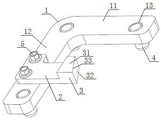
FIG. 1 is a schematic structural diagram of the present invention.
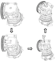
FIG. 2 is a schematic view of the process of the present invention.
In the figure, a fixed seat 1, a first fixed plate 11, a second fixed plate 12, a mounting hole 13, a mounting positioning plate 2, a positioning lug 3, a top surface 31, a side surface 32, a thrust line 33, a positioning pin 4 and a bolt piece 5.
Detailed Description
The present invention will be further described with reference to the following embodiments.
Referring to fig. 1, a frock of accurate control coupling angle and height, includes fixing base 1, installation locating plate 2, fixing base 1 is fixed on automobile-used annex, the top of fixing base 1 and the one end fixed connection of installation locating plate 2, and the other end of installation locating plate 2 is provided with positioning bump 3, positioning bump 3's top surface 31 is high binding face, and positioning bump 3's side 32 is the angle binding face, the top surface 31 forms the thrust line 33 of coupling with the junction of side 32.
The thrust line 33 is the intersection line of the central plane of the pipe joint and the bottom of the pipe joint.
The tool further comprises a positioning pin 4, one end of the positioning pin 4 is in interference fit with a mounting hole 13 formed in the fixing seat 1, and the other end of the positioning pin 4 is in clearance fit with a positioning pin hole in the automobile accessory.
Fixing base 1 is L shaped plate structure, including a fixed plate 11, No. two fixed plates 12 of mutually perpendicular connection, all seted up mounting hole 13 on a fixed plate 11, No. two fixed plates 12, and a fixed plate 11 and 2 fixed connection of installation locating plate.
The first fixing plate 11 is fixedly connected with the mounting positioning plate 2 through a bolt piece 5.
The number of the mounting holes 13 is at least two.
A design method of a tool for accurately controlling the angle and the height of a pipe joint sequentially comprises the following steps:
firstly, selecting a plurality of fixing holes with position degree requirements near a pipe joint mounting hole on an automobile accessory, and processing the fixing holes into positioning pin holes in clearance fit with the positioning pins 4 to form stepped holes;
secondly, determining the position and the bore diameter of the mounting hole 13 according to the outer diameter of the positioning pin and the distance between the positioning pin holes on the vehicle accessory;
and thirdly, determining the theoretical position of the thrust line 33 according to the theoretical installation angle and height of the pipe joint on the three-dimensional model, and designing the positioning bump 3 according to the theoretical position of the thrust line 33.
Referring to fig. 2, a method for using a tool for accurately controlling the angle and height of a pipe joint specifically comprises the following steps: the fixed seat 1 is fixed on an accessory for a vehicle, the pipe joint is screwed from an initial screwing angle until an intersection line of a central plane of the pipe joint and the bottom of the pipe joint is superposed with a thrust line 33, and then the pipe joint locking nut is screwed according to a required torque, wherein the initial screwing angle is obtained by calculation according to the screwing depth of the pipe joint and the thread pitch of the thread.
The initial screwing angle θ =2 pi × a, which is a value of a fractional part of a value obtained by dividing a screwing depth of the pipe joint by a thread pitch of the pipe joint, and which is opposite to a thread turning direction starting from the thrust line 33.
The principle of the invention is illustrated as follows:
the invention provides a tool for accurately controlling the angle and the height of a pipe joint, which effectively solves the problem of large position errors of the angle and the height during the assembly of the pipe joint, reduces the cost for a designer to give way to a hand piece, eliminates the assembly stress of the hand piece, and improves the reliability of a product. The positioning pin 4 is in clearance fit with a positioning pin hole in the vehicle accessory, the clearance is as small as possible, and the position error between the thrust line 33 and the joint mounting hole can be as small as possible, so that the positioning accuracy is ensured; by setting the initial screwing-in angle, the height of the pipe joint assembly can be ensured to meet the requirements.
Vehicle accessories: the vehicle accessory is an assembly body with pipe joint installation angle requirements, such as a power steering pump, a fuel pump, an engine and the like.
Initial screw-in angle: in the present invention, the initial screw-in angle θ =2 pi × a, a is a value of a decimal portion of a value obtained by dividing a screw-in depth of the pipe joint by a screw pitch of the pipe joint, and starting from the thrust line 33, is opposite to the screw direction, and if the pipe joint is designed to have a screw-in depth of 10.5mm and a screw pitch of 2mm, a is 0.25 (10.5/2 =5.25, 0.25 is taken), and the initial screw-in angle is 90 ° rotated from the thrust line (33) in a direction opposite to the screw direction.
Mounting hole 13: the number of the mounting holes 13 is at least 2, so that the stability is ensured; when a number of 3 or more is selected, two play a positioning role and the rest only play an auxiliary fixing role in order to prevent over-constraint.
Example 1:
referring to fig. 1, a tool for accurately controlling the installation angle and height of a pipe joint comprises a fixed seat 1, an installation positioning plate 2 and a positioning pin 4, wherein the fixed seat 1 is of an L-shaped plate structure and comprises a first fixing plate 11 and a second fixing plate 12 which are vertically connected with each other, a mounting hole 13 is formed in one end of the first fixing plate 11, which is far away from the second fixing plate 12, the joint of the first fixing plate 11 and the second fixing plate 12, and one end of the second fixing plate 12, which is far away from the first fixing plate 11, the upper end of the positioning pin 4 is in interference fit with the mounting hole 13, the lower end of the positioning pin 4 is in clearance fit with a positioning pin hole in an air compressor, the installation positioning plate 2 is positioned above the first fixing plate 11, one end of the installation positioning plate 2 is fixedly connected with the first fixing plate 11 through a bolt piece 5, the other end of the installation positioning plate 2 is provided with a positioning bump 3, and the top surface 31 of the positioning bump 3 is a high-joint surface, the side surface 32 of the positioning convex block 3 is an angle joint surface, and the joint of the top surface 31 and the side surface 32 forms a thrust line 33 of the pipe joint.
Example 2:
the tool in embodiment 1 is designed and obtained according to the following steps in sequence:
the method comprises the following steps that firstly, 3 fixing holes which are positioned near a pipe joint mounting hole on the air compressor and have position degree requirements with the fixing holes are selected and machined into positioning pin holes which are in clearance fit with positioning pins 4;
secondly, determining the position and the hole diameter of a mounting hole 13 which is in interference fit with the positioning pin 4 on the fixing plate according to the hole diameter of the positioning pin and the distance between the positioning pin holes on the air compressor;
and thirdly, determining the position of the thrust line 33 according to the installation angle and the height of the pipe joint, and designing the positioning lug 3 according to the position of the thrust line 33.
Example 3:
referring to fig. 2, the use method of the tool in embodiment 1 specifically includes: the positioning pin 4 is firstly inserted into a positioning pin hole of an air compressor for fixing, then the pipe joint is screwed from an initial screwing angle until an intersection line of a central plane of the pipe joint and the bottom of the pipe joint is superposed with a thrust line 33, and then the pipe joint locking nut is screwed according to a required moment, wherein the initial screwing angle theta =2 pi x A, A is a value of a decimal part in a numerical value obtained by dividing the screwing depth of the pipe joint by a thread pitch of the pipe joint, and the angle is opposite to a thread screwing direction by taking a thrust line as a starting point.
Claims (7)
1. The utility model provides a frock of accurate control coupling angle and height which characterized in that:
the frock includes fixing base (1), installation locating plate (2), locating pin (4), fixing base (1) is fixed on automobile-used annex, the top of fixing base (1) and the one end fixed connection of installation locating plate (2), and the other end of installation locating plate (2) is provided with positioning lug (3), top surface (31) of positioning lug (3) are high binding face, and side (32) of positioning lug (3) are angle binding face, top surface (31) and the junction of side (32) form thrust line (33) of coupling, thrust line (33) are the intersection line of the central plane of coupling and coupling bottom, mounting hole (13) interference fit of seting up on one end of locating pin (4) and fixing base (1), the other end of locating pin (4) and automobile-used annex on locating pin hole clearance fit.
2. The tool for accurately controlling the angle and the height of the pipe joint according to claim 1, wherein the tool comprises: fixing base (1) is L shaped plate structure, including a fixed plate (11), No. two fixed plates (12) of mutually perpendicular connection, mounting hole (13) have all been seted up on a fixed plate (11), No. two fixed plates (12), and fixed plate (11) and installation locating plate (2) fixed connection.
3. The tool for accurately controlling the angle and the height of the pipe joint according to claim 2, wherein the tool comprises: the first fixing plate (11) is fixedly connected with the mounting positioning plate (2) through a bolt piece (5).
4. The tool for accurately controlling the angle and the height of the pipe joint according to claim 1, wherein the tool comprises: the number of the mounting holes (13) is at least two.
5. The design method of the tool for accurately controlling the angle and the height of the pipe joint according to claim 1, characterized by comprising the following steps:
the design method sequentially comprises the following steps:
firstly, selecting a plurality of fixing holes with position degree requirements near a pipe joint mounting hole on an automobile accessory, and processing the fixing holes into positioning pin holes in clearance fit with positioning pins (4) to form stepped holes;
secondly, determining the position and the bore diameter of the mounting hole (13) according to the outer diameter of the positioning pin and the distance between the positioning pin holes on the vehicle accessory;
and thirdly, determining the theoretical position of the thrust line (33) according to the theoretical installation angle and height of the pipe joint on the three-dimensional model, and designing the positioning bump (3) according to the theoretical position of the thrust line (33).
6. The use method of the tool for accurately controlling the angle and the height of the pipe joint according to claim 1 is characterized in that:
the using method comprises the following steps: the method comprises the steps of fixing a fixing seat (1) on an accessory for a vehicle, screwing a pipe joint from an initial screwing angle until an intersection line of a central plane of the pipe joint and the bottom of the pipe joint is overlapped with a thrust line (33), and screwing a locking nut of the pipe joint according to required torque, wherein the initial screwing angle is obtained by calculation according to the screwing depth and the thread pitch of the pipe joint.
7. The use method of the tool for accurately controlling the angle and the height of the pipe joint according to claim 6, is characterized in that: the initial screwing angle theta =2 pi x A, wherein A is a value of a decimal part of a value obtained by dividing a screwing depth of the pipe joint by a thread pitch of the pipe joint, and the angle is opposite to a thread screwing direction with a thrust line (33) as a starting point.
Priority Applications (1)
| Application Number | Priority Date | Filing Date | Title |
|---|---|---|---|
| CN202011037142.7A CN112171555B (en) | 2020-09-28 | 2020-09-28 | Tool for accurately controlling angle and height of pipe joint, design and use method |
Applications Claiming Priority (1)
| Application Number | Priority Date | Filing Date | Title |
|---|---|---|---|
| CN202011037142.7A CN112171555B (en) | 2020-09-28 | 2020-09-28 | Tool for accurately controlling angle and height of pipe joint, design and use method |
Publications (2)
| Publication Number | Publication Date |
|---|---|
| CN112171555A CN112171555A (en) | 2021-01-05 |
| CN112171555B true CN112171555B (en) | 2022-05-17 |
Family
ID=73944394
Family Applications (1)
| Application Number | Title | Priority Date | Filing Date |
|---|---|---|---|
| CN202011037142.7A Active CN112171555B (en) | 2020-09-28 | 2020-09-28 | Tool for accurately controlling angle and height of pipe joint, design and use method |
Country Status (1)
| Country | Link |
|---|---|
| CN (1) | CN112171555B (en) |
Families Citing this family (1)
| Publication number | Priority date | Publication date | Assignee | Title |
|---|---|---|---|---|
| CN113334293B (en) * | 2021-06-18 | 2024-12-10 | 广西玉柴机器股份有限公司 | A pre-assembled tool for a steering pump joint |
Citations (6)
| Publication number | Priority date | Publication date | Assignee | Title |
|---|---|---|---|---|
| CN201596989U (en) * | 2010-02-10 | 2010-10-06 | 辽宁太克液压机械集团有限公司 | Steering pump elbow assembling and positioning fixture |
| CN103807554A (en) * | 2013-12-16 | 2014-05-21 | 大连液压件有限公司 | Universal connecting plate |
| CN104084906A (en) * | 2014-05-27 | 2014-10-08 | 大连液压件有限公司 | Quick angle positioning and mounting device for bend |
| KR20150144087A (en) * | 2014-06-16 | 2015-12-24 | 변희송 | Elbow fixing device for plant piping (Elbow fix) |
| CN206373820U (en) * | 2017-01-17 | 2017-08-04 | 北京福田康明斯发动机有限公司 | Service tee angle controls frock |
| CN111590351A (en) * | 2020-04-30 | 2020-08-28 | 中国航发南方工业有限公司 | Pipe joint clamp |
-
2020
- 2020-09-28 CN CN202011037142.7A patent/CN112171555B/en active Active
Patent Citations (6)
| Publication number | Priority date | Publication date | Assignee | Title |
|---|---|---|---|---|
| CN201596989U (en) * | 2010-02-10 | 2010-10-06 | 辽宁太克液压机械集团有限公司 | Steering pump elbow assembling and positioning fixture |
| CN103807554A (en) * | 2013-12-16 | 2014-05-21 | 大连液压件有限公司 | Universal connecting plate |
| CN104084906A (en) * | 2014-05-27 | 2014-10-08 | 大连液压件有限公司 | Quick angle positioning and mounting device for bend |
| KR20150144087A (en) * | 2014-06-16 | 2015-12-24 | 변희송 | Elbow fixing device for plant piping (Elbow fix) |
| CN206373820U (en) * | 2017-01-17 | 2017-08-04 | 北京福田康明斯发动机有限公司 | Service tee angle controls frock |
| CN111590351A (en) * | 2020-04-30 | 2020-08-28 | 中国航发南方工业有限公司 | Pipe joint clamp |
Also Published As
| Publication number | Publication date |
|---|---|
| CN112171555A (en) | 2021-01-05 |
Similar Documents
| Publication | Publication Date | Title |
|---|---|---|
| CN201214176Y (en) | Platform of flexible clamper for automobile welding and assembling | |
| CN106514354A (en) | Machining tool and method for two end surfaces of cross head pin | |
| CN111702521A (en) | Special-shaped part machining method, clamp and clamp design method | |
| CN112171555A (en) | Tool for accurately controlling angle and height of pipe joint, design and use method | |
| CN201471172U (en) | Machining box body tooling for horizontal machining center | |
| CN206356942U (en) | A kind of processing tool of crosshead pin both ends of the surface | |
| CN219256044U (en) | Measuring tape mounting structure of ceramic tile cutting machine | |
| CN221476216U (en) | Forming assembly frame | |
| CN218518210U (en) | Mounting device for processing and positioning lower part structure of precombustion chamber | |
| CN214722459U (en) | Special fixture for screw sleeve of three-axis screw pump | |
| CN114905431B (en) | Positioning device, positioning method and detection method for white car body damping tower | |
| CN217074585U (en) | Automobile front hood integrated lightweight harness | |
| CN209410356U (en) | Assembly jig | |
| CN202910493U (en) | Rapid accurate positioning tooling | |
| CN217453881U (en) | Zero alignment tool for angular displacement sensor | |
| CN219632672U (en) | Girder joint and stringer installation and size assurance frock | |
| CN210334923U (en) | A dress welds supplementary tool for L2-S type part | |
| CN224223265U (en) | A/C swing head geometric accuracy detection device | |
| CN221539015U (en) | A vertical machining and positioning tool for rail locomotive crank arm | |
| CN223656374U (en) | Positioning tool for front suspension of bazaar | |
| CN223718326U (en) | Axis A supporting seat for five-axis machine | |
| CN222391761U (en) | A deformation-resistant high-precision automobile ball head | |
| CN221549520U (en) | Protractor for assembling connecting rod bolt of diesel engine | |
| CN223789975U (en) | Thin-walled blade precision milling fixture | |
| CN223368865U (en) | Vertical machining center frock |
Legal Events
| Date | Code | Title | Description |
|---|---|---|---|
| PB01 | Publication | ||
| PB01 | Publication | ||
| SE01 | Entry into force of request for substantive examination | ||
| SE01 | Entry into force of request for substantive examination | ||
| GR01 | Patent grant | ||
| GR01 | Patent grant |