Adjustable winding mold for transformer coil
Technical Field
The invention relates to a winding die, in particular to an adjustable winding die for a transformer coil.
Background
A Transformer (Transformer) is a device that changes an alternating-current voltage by using the principle of electromagnetic induction, and main components are a primary coil, a secondary coil, and an iron core (magnetic core). The main functions are as follows: voltage transformation, current transformation, impedance transformation, isolation, voltage stabilization (magnetic saturation transformer), and the like, and transformers can be classified into: distribution transformers, power transformers, fully enclosed transformers, combined transformers, dry-type transformers, oil-immersed transformers, single-phase transformers, electric furnace transformers, rectifier transformers, reactors, anti-interference transformers, lightning protection transformers, box-type transformer test transformers, corner transformers, high current transformers, excitation transformers, etc.
At present, most of the existing transformer winding dies are difficult to take out after winding is completed, a large amount of working time is consumed, and the yield is reduced. Therefore, we improve this and propose an adjustable winding mold for transformer coil.
Disclosure of Invention
In order to overcome the defects in the prior art, the invention provides an adjustable winding die for a transformer coil.
In order to solve the technical problems, the invention provides the following technical scheme:
the invention relates to an adjustable winding die for a transformer coil, which comprises a bottom plate and a fixed column, wherein the top of the bottom plate is provided with the fixed column, the middle part of the bottom plate is provided with a motor, the top of the motor is provided with a rotating shaft, the top of the rotating shaft is provided with a base, a groove is arranged in the middle of the base, a fixed block is arranged on one side of the groove, a winding die body is arranged in the groove, the top of the fixing column is provided with a top plate, the winding die body comprises a first fixing plate, one side of the first fixing plate is provided with a first fixing groove, the top of the first fixing plate is provided with a positioning groove, the middle part of the first fixing plate is provided with a distance groove, the inside of constant head tank is equipped with the locating lever, the inside in distance groove is equipped with the distance pole, the top of distance pole is equipped with the threaded rod, threaded rod and distance pole pass through spiral line swing joint.
As a preferable technical scheme of the invention, a second fixing plate is arranged at the top of the threaded rod, and the second fixing plate and the first fixing plate are the same in shape.
As a preferred technical solution of the present invention, one side of the second fixing plate is provided with two second positioning grooves, and the two second positioning grooves are symmetrically arranged on two sides of the second positioning plate respectively.
As a preferred technical solution of the present invention, the surface of the second fixing plate is provided with a plurality of through holes, and the through holes penetrate through the second positioning plate.
As a preferable technical scheme of the invention, a distance hole is arranged in the middle of the second positioning plate, and a thread is arranged on the inner wall of the distance hole.
As a preferred technical scheme of the invention, the bottom of the motor is connected with the bottom plate in an embedded manner and is fixed by screws, the top of the rotating shaft is provided with a gear, and the bottom of the base is provided with a gear groove matched and fixed with the gear.
As a preferred technical solution of the present invention, four fixing columns are provided, respectively located at four corners of the bottom plate, and fixed to the bottom plate by welding.
As a preferred technical scheme of the invention, the top of the fixed block is provided with a fixed part, and the fixed part comprises a spring and a clamping plate.
The invention has the beneficial effects that: the adjustable winding die for the transformer coil realizes the rotation of a base through the arranged motor, improves the working efficiency, realizes the fixation of a winding die body through the arranged groove and the arranged fixing piece, improves the stability, realizes the protection function during working through the arranged top plate, improves the safety, realizes the separation of a wire and the winding die through the arranged positioning rod, solves the problems that most of the existing transformer winding dies are difficult to take out after winding is completed, consumes a large amount of working time, reduces the yield, is provided with a second fixing plate at the top of a threaded rod, has the same shape as the first fixing plate, is provided with a second fixing plate at the top of the threaded rod, realizes the fixation during winding, improves the stability, is provided with a second fixing groove at one side of the second fixing plate, and is provided with two second fixing grooves, the symmetry sets up in the both sides of second locating plate respectively, is equipped with the second fixed slot through one side of second fixed plate, has realized the fixed of this wire winding mould body, has improved stability.
Drawings
The accompanying drawings, which are included to provide a further understanding of the invention and are incorporated in and constitute a part of this specification, illustrate embodiments of the invention and together with the description serve to explain the principles of the invention and not to limit the invention. In the drawings:
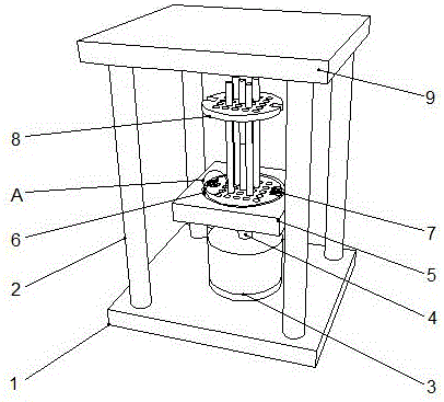
FIG. 1 is a schematic structural diagram of an adjustable winding mold for a transformer coil according to the present invention;
FIG. 2 is a schematic view of a partial structure of an adjustable winding mold for a transformer coil according to the present invention;
FIG. 3 is a schematic cross-sectional view of an adjustable winding mold for a transformer coil according to the present invention;
fig. 4 is an enlarged structural diagram of an adjustable winding mold a for a transformer coil according to the present invention.
In the figure: 1. a base plate; 2. fixing a column; 3. a motor; 4. a rotating shaft; 5. a base; 6. a groove; 7. a fixed block; 8. a winding die body; 9. a top plate; 10. a first fixing plate; 11. a first fixing groove; 12. positioning a groove; 13. a distance groove; 14. positioning a rod; 15. a distance rod; 16. a threaded rod; 17. a second fixing plate; 18. a second fixing groove; 19. a through hole; 20. a distance hole; 21. and a fixing member.
Detailed Description
The preferred embodiments of the present invention will be described in conjunction with the accompanying drawings, and it will be understood that they are described herein for the purpose of illustration and explanation and not limitation.
Example (b): as shown in the figures 1 and 2, respectively, as shown in fig. 3 and 4, the adjustable winding mold for the transformer coil comprises a bottom plate 1 and fixed columns 2, the fixed columns 2 are arranged at the top of the bottom plate 1, a motor 3 is arranged in the middle of the bottom plate 1, a rotating shaft 4 is arranged at the top of the motor 3, a base 5 is arranged at the top of the rotating shaft 4, a groove 6 is arranged in the middle of the base 5, a fixed block 7 is arranged at one side of the groove 6, a winding mold body 8 is arranged in the groove 6, a top plate 9 is arranged at the top of the fixed columns 2, the winding mold body 8 comprises a first fixed plate 10, a first fixed groove 11 is arranged at one side of the first fixed plate 10, a positioning groove 12 is arranged at the top of the first fixed plate 10, a distance groove 13 is arranged in the middle of the first fixed plate 10, a positioning rod 14 is arranged inside the positioning groove 12, a distance rod 15 is arranged inside the distance groove 13, a threaded rod 16 is arranged at the top of the distance rod 15, and the threaded rod 16 and the distance rod 15 are movably connected through spiral grains.
Wherein, the top of threaded rod 16 is equipped with second fixed plate 17, and second fixed plate 17 is the same with first fixed plate 10 molding, is equipped with second fixed plate 17 through the top of threaded rod 16, has realized the fixed when wire winding, has improved stability.
Wherein, one side of second fixed plate 17 is equipped with second fixed slot 18, and second fixed slot 18 is equipped with two, and the symmetry sets up in the both sides of second fixed plate 17 respectively, is equipped with second fixed slot 18 through one side of second fixed plate 17, has realized this winding die body 8's fixed, has improved stability.
Wherein, the surface of second fixed plate 17 is equipped with through-hole 19, and through-hole 19 is equipped with a plurality of, and runs through second fixed plate 17, is equipped with through-hole 19 through the surface of second fixed plate 17, has realized the location when this winding mould body 8 winds the wire, has improved the functionality.
Wherein, the middle part of second fixed plate 17 is equipped with distance hole 20, and the inner wall of distance hole 20 is equipped with the screw thread, is equipped with distance hole 20 through the middle part of second fixed plate 17, has realized that this winding mould body 8's distance is fixed, has improved the convenience.
Wherein, motor 3's bottom and bottom plate 1 are through embedded connection, and pass through the screw fixation, and the top of pivot 4 is equipped with the gear, and base 5's bottom is equipped with the gear groove fixed with the gear cooperation, and bottom plate 1 through embedded connection through motor 3 have realized motor 3's fixing, have improved stability.
Wherein, fixed column 2 is equipped with four, is located four corners of bottom plate 1 respectively, and fixed through welding and bottom plate 1, is equipped with four through fixed column 2, is located four corners of bottom plate 1 respectively, has realized 8 protect function of this winding die body, has improved the security.
Wherein, the top of fixed block 7 is equipped with mounting 21, and mounting 21 includes spring and cardboard, is equipped with mounting 21 through the top of fixed block 7, has realized this wire winding mould body 8's fixed, has improved stability.
When the winding die works, one end of a winding die body 8 is placed into the groove 6, the first fixing groove 11 and the fixing block 7 are clamped, the fixing piece 21 is pushed, the clamping plate presses the first fixing plate 10 to achieve the fixing effect, the motor 3 is started to drive the rotating shaft 4 to rotate, the base 5 is driven to rotate, when the base 5 rotates, the winding die body 8 is driven to rotate to perform winding, after the winding is completed, the positioning rod 14 is pulled out, a finished product is taken out, through holes 19 are formed in the surface of the second fixing plate 17 and are provided with a plurality of through holes 19 and penetrate through the second fixing plate 17, the positioning during the winding of the winding die body 8 is realized through the through holes 19 formed in the surface of the second fixing plate 17, a distance hole 20 is formed in the middle of the second fixing plate 17, threads are arranged on the inner wall of the distance hole 20, a distance hole 20 is formed in the middle of the second fixing plate 17, and the distance fixing of the winding die body 8 is realized, fixed column 2 is equipped with four, is located four corners of bottom plate 1 respectively, and fixed through welding and bottom plate 1, and fixed column 2 is equipped with four, is located four corners of bottom plate 1 respectively, has realized 8 protect function of this wire winding mould body.
Finally, it should be noted that: in the description of the present invention, it should be noted that the terms "vertical", "upper", "lower", "horizontal", and the like indicate orientations or positional relationships based on those shown in the drawings, and are only for convenience of describing the present invention and simplifying the description, but do not indicate or imply that the referred device or element must have a specific orientation, be constructed in a specific orientation, and be operated, and thus, should not be construed as limiting the present invention.
In the description of the present invention, it should also be noted that, unless otherwise explicitly specified or limited, the terms "disposed," "mounted," "connected," and "connected" are to be construed broadly and may, for example, be fixedly connected, detachably connected, or integrally connected; can be mechanically or electrically connected; they may be connected directly or indirectly through intervening media, or they may be interconnected between two elements. The specific meanings of the above terms in the present invention can be understood by those skilled in the art according to specific situations.
Although the present invention has been described in detail with reference to the foregoing embodiments, it will be apparent to those skilled in the art that changes may be made in the embodiments and/or equivalents thereof without departing from the spirit and scope of the invention. Any modification, equivalent replacement, or improvement made within the spirit and principle of the present invention should be included in the protection scope of the present invention.