CN112145335A - Wave energy collecting system for power generation and working method thereof - Google Patents
Wave energy collecting system for power generation and working method thereof Download PDFInfo
- Publication number
- CN112145335A CN112145335A CN202011088632.XA CN202011088632A CN112145335A CN 112145335 A CN112145335 A CN 112145335A CN 202011088632 A CN202011088632 A CN 202011088632A CN 112145335 A CN112145335 A CN 112145335A
- Authority
- CN
- China
- Prior art keywords
- energy collecting
- wave energy
- platform
- wave
- collecting bag
- Prior art date
- Legal status (The legal status is an assumption and is not a legal conclusion. Google has not performed a legal analysis and makes no representation as to the accuracy of the status listed.)
- Granted
Links
- 238000010248 power generation Methods 0.000 title claims abstract description 50
- 238000000034 method Methods 0.000 title claims abstract description 22
- XLYOFNOQVPJJNP-UHFFFAOYSA-N water Substances O XLYOFNOQVPJJNP-UHFFFAOYSA-N 0.000 claims abstract description 110
- 230000000694 effects Effects 0.000 claims abstract description 26
- 230000009471 action Effects 0.000 claims abstract description 9
- 238000006073 displacement reaction Methods 0.000 claims abstract description 5
- 230000005611 electricity Effects 0.000 claims description 10
- 230000008569 process Effects 0.000 claims description 8
- 238000007667 floating Methods 0.000 claims description 6
- 230000000712 assembly Effects 0.000 claims description 3
- 238000000429 assembly Methods 0.000 claims description 3
- 238000011176 pooling Methods 0.000 claims 1
- 230000006872 improvement Effects 0.000 description 8
- 238000007789 sealing Methods 0.000 description 5
- 230000002238 attenuated effect Effects 0.000 description 4
- 238000006243 chemical reaction Methods 0.000 description 4
- 238000013461 design Methods 0.000 description 3
- 238000005516 engineering process Methods 0.000 description 3
- 230000003139 buffering effect Effects 0.000 description 2
- 239000003638 chemical reducing agent Substances 0.000 description 2
- 230000007547 defect Effects 0.000 description 2
- 238000011161 development Methods 0.000 description 2
- 238000010586 diagram Methods 0.000 description 2
- 238000005259 measurement Methods 0.000 description 2
- 230000010355 oscillation Effects 0.000 description 2
- 230000010356 wave oscillation Effects 0.000 description 2
- 241001391944 Commicarpus scandens Species 0.000 description 1
- 230000005540 biological transmission Effects 0.000 description 1
- 230000000903 blocking effect Effects 0.000 description 1
- 238000004140 cleaning Methods 0.000 description 1
- 238000009826 distribution Methods 0.000 description 1
- 238000003912 environmental pollution Methods 0.000 description 1
- 238000001125 extrusion Methods 0.000 description 1
- 230000003116 impacting effect Effects 0.000 description 1
- 238000004519 manufacturing process Methods 0.000 description 1
- 239000000463 material Substances 0.000 description 1
- 238000012986 modification Methods 0.000 description 1
- 230000004048 modification Effects 0.000 description 1
- 238000012544 monitoring process Methods 0.000 description 1
- 239000002077 nanosphere Substances 0.000 description 1
- 230000000149 penetrating effect Effects 0.000 description 1
- 230000000737 periodic effect Effects 0.000 description 1
- 230000002035 prolonged effect Effects 0.000 description 1
- 238000011160 research Methods 0.000 description 1
- 239000013535 sea water Substances 0.000 description 1
- 238000003892 spreading Methods 0.000 description 1
- 230000007480 spreading Effects 0.000 description 1
- 238000003466 welding Methods 0.000 description 1
Images






Classifications
-
- F—MECHANICAL ENGINEERING; LIGHTING; HEATING; WEAPONS; BLASTING
- F03—MACHINES OR ENGINES FOR LIQUIDS; WIND, SPRING, OR WEIGHT MOTORS; PRODUCING MECHANICAL POWER OR A REACTIVE PROPULSIVE THRUST, NOT OTHERWISE PROVIDED FOR
- F03B—MACHINES OR ENGINES FOR LIQUIDS
- F03B13/00—Adaptations of machines or engines for special use; Combinations of machines or engines with driving or driven apparatus; Power stations or aggregates
- F03B13/12—Adaptations of machines or engines for special use; Combinations of machines or engines with driving or driven apparatus; Power stations or aggregates characterised by using wave or tide energy
- F03B13/14—Adaptations of machines or engines for special use; Combinations of machines or engines with driving or driven apparatus; Power stations or aggregates characterised by using wave or tide energy using wave energy
- F03B13/22—Adaptations of machines or engines for special use; Combinations of machines or engines with driving or driven apparatus; Power stations or aggregates characterised by using wave or tide energy using wave energy using the flow of water resulting from wave movements to drive a motor or turbine
-
- F—MECHANICAL ENGINEERING; LIGHTING; HEATING; WEAPONS; BLASTING
- F03—MACHINES OR ENGINES FOR LIQUIDS; WIND, SPRING, OR WEIGHT MOTORS; PRODUCING MECHANICAL POWER OR A REACTIVE PROPULSIVE THRUST, NOT OTHERWISE PROVIDED FOR
- F03B—MACHINES OR ENGINES FOR LIQUIDS
- F03B13/00—Adaptations of machines or engines for special use; Combinations of machines or engines with driving or driven apparatus; Power stations or aggregates
- F03B13/12—Adaptations of machines or engines for special use; Combinations of machines or engines with driving or driven apparatus; Power stations or aggregates characterised by using wave or tide energy
- F03B13/14—Adaptations of machines or engines for special use; Combinations of machines or engines with driving or driven apparatus; Power stations or aggregates characterised by using wave or tide energy using wave energy
- F03B13/141—Adaptations of machines or engines for special use; Combinations of machines or engines with driving or driven apparatus; Power stations or aggregates characterised by using wave or tide energy using wave energy with a static energy collector
- F03B13/142—Adaptations of machines or engines for special use; Combinations of machines or engines with driving or driven apparatus; Power stations or aggregates characterised by using wave or tide energy using wave energy with a static energy collector which creates an oscillating water column
-
- F—MECHANICAL ENGINEERING; LIGHTING; HEATING; WEAPONS; BLASTING
- F03—MACHINES OR ENGINES FOR LIQUIDS; WIND, SPRING, OR WEIGHT MOTORS; PRODUCING MECHANICAL POWER OR A REACTIVE PROPULSIVE THRUST, NOT OTHERWISE PROVIDED FOR
- F03B—MACHINES OR ENGINES FOR LIQUIDS
- F03B13/00—Adaptations of machines or engines for special use; Combinations of machines or engines with driving or driven apparatus; Power stations or aggregates
- F03B13/12—Adaptations of machines or engines for special use; Combinations of machines or engines with driving or driven apparatus; Power stations or aggregates characterised by using wave or tide energy
- F03B13/14—Adaptations of machines or engines for special use; Combinations of machines or engines with driving or driven apparatus; Power stations or aggregates characterised by using wave or tide energy using wave energy
- F03B13/16—Adaptations of machines or engines for special use; Combinations of machines or engines with driving or driven apparatus; Power stations or aggregates characterised by using wave or tide energy using wave energy using the relative movement between a wave-operated member, i.e. a "wom" and another member, i.e. a reaction member or "rem"
- F03B13/20—Adaptations of machines or engines for special use; Combinations of machines or engines with driving or driven apparatus; Power stations or aggregates characterised by using wave or tide energy using wave energy using the relative movement between a wave-operated member, i.e. a "wom" and another member, i.e. a reaction member or "rem" wherein both members, i.e. wom and rem are movable relative to the sea bed or shore
-
- Y—GENERAL TAGGING OF NEW TECHNOLOGICAL DEVELOPMENTS; GENERAL TAGGING OF CROSS-SECTIONAL TECHNOLOGIES SPANNING OVER SEVERAL SECTIONS OF THE IPC; TECHNICAL SUBJECTS COVERED BY FORMER USPC CROSS-REFERENCE ART COLLECTIONS [XRACs] AND DIGESTS
- Y02—TECHNOLOGIES OR APPLICATIONS FOR MITIGATION OR ADAPTATION AGAINST CLIMATE CHANGE
- Y02E—REDUCTION OF GREENHOUSE GAS [GHG] EMISSIONS, RELATED TO ENERGY GENERATION, TRANSMISSION OR DISTRIBUTION
- Y02E10/00—Energy generation through renewable energy sources
- Y02E10/30—Energy from the sea, e.g. using wave energy or salinity gradient
Landscapes
- Engineering & Computer Science (AREA)
- Chemical & Material Sciences (AREA)
- Combustion & Propulsion (AREA)
- Mechanical Engineering (AREA)
- General Engineering & Computer Science (AREA)
- Other Liquid Machine Or Engine Such As Wave Power Use (AREA)
Abstract
The invention relates to the technical field of power generation, in particular to a wave energy collecting system for power generation and a working method thereof. When the energy collecting bag works, the upward acting force formed when the oscillating water body fluctuates upwards is utilized to discharge the water in the energy collecting bag, so that the energy collecting bag is in a curved and shriveled shape; then when the oscillating water body fluctuates downwards, water flow is injected into the energy collecting bag downwards until the energy collecting bag expands, the water flow is blocked by the wave energy collecting platform to limit displacement, so that the water flow can impact the inner wall of the energy collecting bag to form a water hammer effect, and a taper pipe at the bottom of the energy collecting bag can also form a narrow pipe effect, so that under the combined action of the water hammer effect and the narrow pipe effect, the water flow can form instantaneous high-pressure water jet, and the high-pressure water jet is led to power generation equipment, so that the wave energy can be converted into electric energy. Therefore, the wave energy power generation equipment can gradually attenuate the wave height of the waves after the wave energy is collected, and efficiently converts the wave energy into electric energy, so that the utilization rate of the wave energy can be effectively improved.
Description
Technical Field
The invention relates to the technical field of power generation, in particular to a wave energy collecting system for power generation and a working method thereof.
Background
Ocean energy is an inexhaustible clean energy and mainly comprises wave energy, tidal current energy, tidal energy, temperature difference energy and the like. In the current development of new energy, ocean energy is attracting attention as a clean energy source. The wave energy is one of the forms of ocean energy represented by kinetic energy. The temperature of the sun raises the temperature of the air due to the disparity in the surface temperatures of air and water, and the rise in air temperature generates wind. The action of sea wind and water generates waves, the waves on the sea surface alternately surge, and the energy generated by the surge is wave energy. The development and utilization of wave energy is very important to alleviate the energy crisis and reduce environmental pollution.
At present, wave energy power generation modes are thousands of, and are mainly divided into three types, namely mechanical type, pneumatic type and hydraulic type according to energy intermediate conversion links, but equipment adopting the three types of wave energy power generation modes has the defects of high manufacturing cost, low wave energy conversion rate, poor weather resistance and the like. In view of the above, a nano-sphere power generation technology is emerging at present, but the power generation technology is more suitable for utilization of offshore miscellaneous and broken waves, and the utilization rate of the huge waves of long waves is low. Therefore, how to improve the utilization rate of wave energy is always a difficult point of wave energy research.
Disclosure of Invention
Aiming at the defects brought forward by the background technology, the invention provides a wave energy collecting system for power generation and a working method thereof, so as to solve the problem of low wave energy utilization rate of the existing wave energy power generation system.
The invention adopts the following technical scheme:
a wave energy collecting system for generating electricity, comprising a wave energy collecting platform and a platform adjustment means, wherein,
the wave energy collecting platform comprises:
the energy collecting bag is expanded, the upper end of the energy collecting bag is a straight pipe, the middle of the energy collecting bag is a conical pipe with a large upper part and a small lower part, the lower end of the energy collecting bag is a bent guide pipe, and the guide pipe is connected to the power input end of power generation equipment;
a float connected to the energy collection bag;
the platform adjusting device comprises:
a pull wire to pull the energy collection bag to remain below the sea surface.
As a further improvement, the energy collecting bag is provided with a flared opening which is gradually enlarged upwards above the straight pipe.
As a further improvement, the energy collecting bag is provided with a plurality of energy collecting bags, and the plurality of energy collecting bags are sequentially connected and distributed in an array; the guide pipes at the bottoms of the energy collecting bags are connected to a main pipe, and the main pipe is connected to a power input end of power generation equipment.
As a further improvement, the guide pipes at the bottoms of the energy collecting bags in the same row in the wave energy collecting platform are connected to the same branch pipe, each branch pipe is connected to the main pipe, and the branch pipes are connected with buffering barrels.
As a further improvement, the buffer barrel is a sealed container with gas inside, and the buffer barrel is connected to the branch pipe through a pipeline, so that the buffer barrel is communicated with the branch pipe.
As a further improvement, and a plurality of energy collecting bags are distributed through a connecting array of connecting frames, the adjusting device has a plurality of groups, the stay wires of each adjusting device are connected to the connecting frames, and each stay wire enables the connecting frames to be evenly stressed and distributed.
As a further improvement, the platform adjusting device further comprises a fixing frame, a chain wheel, a motor assembly and a floating barrel, wherein the fixing frame is fixed on the seabed, the chain wheel is rotatably connected to the fixing frame, the motor assembly is fixed on one side of the fixing frame, and an output shaft of the motor assembly is fixedly connected with the chain wheel; the stay wire is a chain, the stay wire is relatively connected to the other end of the energy collecting bag, bypasses the chain wheel from bottom to top and is connected with the floating barrel, and the stay wire is meshed with the chain wheel.
As a further improvement, the device further comprises a controller, and each platform adjusting device is provided with one controller; the controller receives real-time wave height data and controls the motor assemblies of the platform adjusting devices to operate according to the data.
The working method of the power generation system for generating electricity by wave energy is characterized in that,
providing at least one wave energy collecting platform and a set of power generation equipment, wherein an energy collecting bag of the wave energy collecting platform is positioned below the sea surface, and a guide pipe at the bottom of the energy collecting bag is finally connected to a power input end of the power generation equipment;
when the oscillating water body fluctuates upwards, water in the energy collecting bag of the wave energy collecting platform is discharged, so that the energy collecting bag is in a curved and shriveled shape;
when the oscillating water body fluctuates downwards, water flow is injected into the energy collecting bag downwards until the energy collecting bag expands, and the water flow is blocked by the wave energy collecting platform to limit displacement, so that the water flow can impact the inner wall of the energy collecting bag to form a strong water hammer effect, and a taper pipe at the bottom of the energy collecting bag can also form a narrow pipe effect, so that instantaneous high-pressure water jet formed by the water flow can be converged into the guide pipe under the combined action of the water hammer effect and the narrow pipe effect;
and finally injecting the high-speed water jet into power generation equipment to convert the wave energy into electric energy.
As a further improvement of the working method, the bottoms of the wave energy collecting platforms are connected through pull wires of a plurality of platform adjusting devices, and the energy collecting bags of the wave energy collecting platforms are pulled to be kept below the sea surface through the pull wires; in the process of collecting wave energy by the energy collecting bag, when the wave at the upper position corresponding to the platform adjusting device is higher, the platform adjusting device pulls the pull line downwards to enable the wave energy collecting platform at the position to submerge deeper; when the waves at the upper position corresponding to the platform adjusting device are smaller, the platform adjusting device releases the pull line to enable the wave energy collecting platform at the position to rise to be closer to the sea surface.
From the above description of the structure of the present invention, compared with the prior art, the present invention has the following advantages: when the wave energy collecting platform works, water in the energy collecting bag of the wave energy collecting platform is discharged by using acting force formed when the oscillating water body fluctuates upwards, so that the energy collecting bag is in a curved and shriveled shape; then when the oscillating water body fluctuates downwards, water flow is injected into the energy collecting bag downwards until the energy collecting bag expands, the water flow is blocked by the wave energy collecting platform to limit displacement, so that the water flow can impact the inner wall of the energy collecting bag to form a strong water hammer effect, and a taper pipe at the bottom of the energy collecting bag can also form a narrow pipe effect, so that the water flow can form an instantaneous high-pressure water jet under the combined action of the water hammer effect and the narrow pipe effect. The conversion of wave energy into electric energy can be realized by introducing the high-pressure water jet to a power generation device. Therefore, the wave energy collecting device can collect wave energy to the maximum extent, and effectively convert the wave energy into electric energy to realize power generation, so that the utilization rate of the wave energy is effectively improved.
Drawings
FIG. 1 is a schematic side view of the invention secured to the sea surface.
Fig. 2 is a schematic structural diagram of the energy collecting bag being shriveled due to the fact that the water body is vibrated upwards.
Fig. 3 is a schematic structural diagram of the energy collecting bag expanding caused by the downward oscillation of the water body.
Fig. 4 is a schematic structural view of a connecting frame for connecting a plurality of energy collecting bags.
Fig. 5 is a schematic perspective view of the wave energy collecting platform.
Fig. 6 is a schematic view of the bottom view of fig. 5.
Figure 7 is a side sectional schematic view of a branch tube connected to a manifold.
Fig. 8 is a schematic front view of the adjustment device.
Fig. 9 is a schematic side view of the adjustment device.
Fig. 10 is a schematic view of the position of the wave energy collecting platform relative to the sea surface.
Detailed Description
The following describes embodiments of the present invention with reference to the drawings.
A wave energy harnessing system for generating electricity includes a wave energy collecting platform, a platform adjustment device, and a controller (not shown).
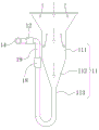
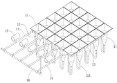
Referring to fig. 2 to 5, the wave energy collecting platform includes a plurality of energy collecting bags 11, and the energy collecting bags 11 are made of flexible waterproof material, specifically, made of waterproof canvas. The expanded structure of the energy collecting bag 11 is sequentially a trumpet-shaped open port, a vertical straight pipe 111, a taper pipe 112 with a large top and a small bottom and a curved guide pipe 113 from top to bottom. Specifically, the guide pipe 113 is bent to form a U-shaped structure, the other end of the guide pipe 113, which is opposite to the taper pipe 112, is connected to the check valve 12, and the check valve 12 is used for preventing water flowing out through the guide pipe 113 from flowing back to the energy collecting bag 11.
The plurality of energy collecting bags 11 are connected by the distribution of the array of connecting frames 17, the connecting frames 17 can be a grid-shaped framework formed by welding pipe fittings as shown in fig. 4, each energy collecting bag 11 is embedded into each grid 171 of the connecting frames 17, and the open ends of the energy collecting bags 11 are fixed to the edges of the grids 171, so that a whole wave energy collecting structure is formed. The connecting frame 17 is further fixed with a plurality of floats 13, upward lift force is formed through buoyancy of the floats 13, the wave energy collecting platform can be supported, and the wave energy collecting platform is prevented from sinking.
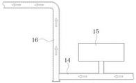
The structure that each energy collecting bag 11 in the wave energy collecting platform is connected to power generation equipment is as shown in fig. 5 and 6, the guide pipes 113 at the bottom of each energy collecting bag 11 in the same row in the wave energy collecting platform are all connected to the same branch pipe 14, each branch pipe 14 is connected to a main pipe 16, the main pipe 16 is connected to the power input end of the power generation equipment, the seawater which is equivalent to be poured into each energy collecting bag 11 is converged into the main pipe 16 through the guide pipes 113 and the branch pipes 14, and the main pipe 16 guides the water flow to the power generation equipment located offshore or onshore for power generation.
In addition, the upper edge of the opening of the energy collecting bag 11 can be fixedly clamped at the edge of the grid 171 of the connecting frame 17 through the connection of a hasp, or the side edge of the opening position of the energy collecting bag 11 and the connecting frame 17 can be fixedly connected through a screw penetrating mode, and the two modes can be both convenient for fixing and disassembling the energy collecting bag 11. The guiding tube 13 and the one-way valve 12 can be connected by a connecting tube 19, and as shown in fig. 2 and 3, the one-way valve 12 is fixedly connected to the branch tube 14, one end of the connecting tube 19 is fixedly connected to the one-way valve 12, and the other end of the connecting tube 19 is connected to the guiding tube 113 by a quick connector 18, which can facilitate the fixing and detaching of the guiding tube 113 and the branch tube 14. It can be seen that the removal of the energy collecting bag 11 from the connecting frame 17 and the removal of the guide tube 113 from the branch tube 14 allow the energy collecting bag 11 to be removed entirely from the connecting frame 17, facilitating the cleaning or replacement of the energy collecting bag 11.
The principle of wave energy collection by the energy collection bag 11 is as follows: the wave is a kind of wave formed by the periodic vibration of the water body leaving the balance position (i.e. water surface) and spreading to a certain direction, and the vibration energy of the water forms kinetic energy. The energy collecting bag has the function that when waves fluctuate up and down due to oscillation and touch the wave energy collecting platform fixed below the sea surface, kinetic energy generated by the waves drives water flow to form dynamic displacement relative to the energy collecting bag 11, namely the water flow in the energy collecting bag 11 is discharged or injected into the energy collecting bag 11. Specifically, as shown in fig. 2, when the oscillating water body fluctuates upwards (i.e. when waves upwelle), an upward acting force is formed to discharge most of the water in each energy collecting bag 11 of the wave energy collecting platform, so that the energy collecting bags 11 are curved and shriveled and close to the wave energy collecting platform, and meanwhile, the water which is not discharged completely is also upwardly close to the wave energy collecting platform along with the curved and shriveled energy collecting bags 11; as shown in fig. 3, when the oscillating water body fluctuates downward (i.e. when waves swell downward), water flow is injected downward into the energy collecting bag 11, and at the same time, the water that is not completely discharged in the energy collecting bag 11 is accelerated to displace downward until the energy collecting bag 11 expands, and the water flow is limited by the blocking of the wave energy collecting platform, so that the water flow impacts the inner wall of the energy collecting bag 11 to form a strong water hammer effect, and the water flow can also form a narrow tube effect through the tapered tube 112 at the lower end of the energy collecting bag 11, so that under the combined action of the water hammer effect and the narrow tube effect, the water flow can form an instantaneous high-pressure water jet, and the impact force formed by the high-pressure water jet can be converted into kinetic energy for driving the power generation equipment to generate power, which is equivalent to that the energy collecting bag 11 finishes the collection of wave energy formed in a. In addition, in the process of energy collection of the energy collecting bags 11, after waves pass through the plurality of energy collecting bags 11 of the wave energy collecting platform along the same direction, the waves are gradually attenuated for multiple times, so that the billows can be changed into big waves and light waves.
The high-pressure water jet collected by the energy collecting bag 11 impacts and flows into the branch pipes 14, then is collected into the main pipe 16 through the branch pipes 14 to form high-flow high-pressure water jet, and then flows into power generation equipment through the main pipe 16, so that the wave energy is converted into electric energy. The power generating equipment may be a hydraulic generator, and the header pipe 16 is connected to a water inlet cavity of the hydraulic generator, namely, the power input end of the power generating equipment. When the system operates, the high-pressure water jet in the main pipe 16 enters the hydraulic generator along the water inlet cavity in an impacting manner, and a huge impact force is formed to push a runner of the hydraulic generator to rotate, so that the acting force of wave oscillation is finally converted into torque power generation.
Referring to fig. 3 again, the guide tube 113 is a U-shaped bent tube after being expanded, and the bent tube structure enables the overall length of the energy collecting bag 11 to have a longer expansion amount, so as to form a buffer, and prevent the energy collecting bag 11 from producing a longer pull on the position of the one-way valve 12 after being instantaneously expanded, thereby preventing the connecting position of the energy collecting bag 11 and the one-way valve 12 from being broken or directly disconnected.
Referring to fig. 7 again, the buffer tank 15 is a sealed container with gas therein, and the buffer tank 15 is connected to the branch pipe 14 through a pipe, so that the buffer tank 15 is communicated with the branch pipe 14. When water flows through the buffer barrel 15, the air pressure in the buffer barrel 15 is compressed to enable the air pressure in the buffer barrel 15 to rise, instantaneous force of the water flows can be reduced by utilizing the high-pressure relative extrusion water flows, and therefore the buffer barrel 15 can also be used for buffering and reducing impact force of the water flows, because the high-pressure water jet flows are instantaneous high-pressure jet flows, if the buffer barrel 15 is not installed, the branch pipes 14 are easy to break, the instantaneous force of the water flows can be reduced under the action of the buffer barrel 15, the water flows can form constant-pressure water pressure, and pipelines can be effectively prevented from breaking, so that the service life of the power generation system is prolonged.
Referring to fig. 8 and 9, the platform adjusting device includes a pull line 34, a fixing frame 31, a chain wheel 33, a motor assembly 35 and a float bucket 32. Referring again to fig. 1, the platform adjusting device has a plurality of sets, the guy wires 34 of each adjusting device are connected to the connecting frame 17, and each guy wire 34 enables the connecting frame 17 to be evenly stressed, i.e. each energy collecting bag 11 on the connecting frame 17 is kept fixed at a specific depth position by the simultaneous traction of each guy wire 34. The buoyancy barrel 32 is a container (i.e. an empty barrel) with a closed cavity inside, the structure enables the buoyancy barrel 32 to keep upward buoyancy, and the sum of the buoyancy formed by each buoyancy barrel 32 is consistent with the buoyancy formed by the wave energy collecting platform. The fixing frame 31 is fixed to the seabed ground, and particularly, the fixing frame 31 can be fixed by driving anchor piles into the seabed and then fixedly connecting the fixing frame 31 with the anchor piles. The chain wheel 33 is rotatably connected to the fixing frame 31, and specifically, as shown in fig. 9, two bearing seats are fixed on the fixing frame 31, a rotating shaft is fixed at the center of the chain wheel 33, and two ends of the rotating shaft are respectively fixed to the two bearing seats. The motor assembly is a power assembly consisting of a brake motor and a worm wheel high speed reducer, the motor assembly 35 is fixed to one side of the fixing frame 31, and an output shaft of the worm wheel high speed reducer is connected with a rotating shaft fixedly connected with the chain wheel 33 through chain transmission. Furthermore, a sealing cover 36 may be further disposed outside the motor assembly, and the position where the rotating shaft of the sprocket 33 extends into the sealing cover 36 may be connected by an oil seal type sealing ring, so that a closed space is formed in the sealing cover 36, thereby effectively protecting the motor assembly 35. The pull wire 34 is a chain, as mentioned above, one end of the pull wire 34 is fixedly connected to the connecting frame 17, the other end of the pull wire 34 is connected to the float bucket 32 after passing around the chain wheel 33 from bottom to top, and the pull wire 34 is engaged with the chain wheel 33. In the above structure, the floating bucket 32 is used for saving the torque output of the motor assembly 35 to the sprocket 33 by utilizing the upward buoyancy of the floating bucket 32; the chain wheel 33 is used for fixing the lower end of the pull wire 34 connected with one side of the connecting frame 17 in a pulling mode, so that the connecting frame 17 is kept at a relatively fixed depth.
In operation, referring to fig. 1 and 8, the pull wire 34 is pulled down by the forward rotation of the chain wheel 33 driven by the motor assembly 35, so that the wave energy collecting platform sinks; the motor assembly 35 drives the chain wheel 33 to rotate reversely, so that a pull wire 34 connected with one end of the connecting frame 17 can be released, the pull wire 34 is lengthened, and the wave energy collecting platform is lifted. Therefore, the depth of the wave energy collecting platform relative to the sea surface can be adjusted by driving the chain wheel 33 to rotate through the motor assembly 35.
The controller may be a PLC controller, and each of the platform adjusting devices is provided with one of the controllers, and the controller may be fixed to the inside of the sealing cover 36, and is configured to control the operation of the motor assembly of each of the platform adjusting devices. Simultaneously, each controller also receives data of the instant water level and wave height above each platform adjusting device. The data of the instant water level and the wave height can be obtained by measuring through a measuring system for monitoring waves in the prior art, and particularly, the measuring system can be a device or a system adopting a wave measuring method such as a sound wave measuring method or an image recognition measuring method.
Furthermore, the wave height data received by each controller may be obtained by configuring a set of measurement system for measuring the wave height in the sea area above the wave energy collecting platform, and simultaneously, the controller of each platform adjusting device is electrically connected to a decoder, the measurement system analyzes and processes the measured wave height data on the wave energy collecting platform corresponding to the position of each platform adjusting device, and then transmits the processed wave height data to each decoder, the decoders convert the obtained data into data instructions of electrical signals and transmit the data instructions to the controller, and the controller controls the motor assembly 35 to operate according to the instructions. During specific work, after the controller receives instant wave height data, the controller controls the motor assemblies 35 of the platform adjusting devices to operate according to instructions generated by the data, so that the chain wheels 33 are driven to pull down or release the pull wires 34, the depth of the wave energy collecting platform relative to the sea surface is adjusted in real time according to the wave height, and the energy collecting bag 11 reaches the optimal depth position.
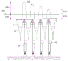
The ideal depth position of the energy collecting bag 11 can be shown in fig. 10, and the closer the wave energy collecting platform rises to the sea surface, the closer the wave energy collecting platform is to the wave height position (i.e. the peak position of the wave in fig. 10), at this time, the larger the downward impact force formed by the water body when the wave energy collecting platform bears the downward surge of the wave, which is equivalent to the stronger wave energy collecting capacity. However, the wave energy collecting platform is not suitable to be too close to the sea surface because the wave energy collecting platform is damaged by the downward impact force formed by the water body when the waves are downwelled. That is to say, the buoyancy design of the wave energy collecting platform needs to be larger than the force formed by the superposition of the downward impact force of the waves and the average water hammer impact force, and under the condition of fixed buoyancy, the position of the wave energy collecting platform relative to the wave height needs to be properly adjusted to avoid bearing the excessive downward impact force of the water body. In addition, the whole structure bearing capacity of the wave energy collecting platform is also considered in specific operation, and the wave energy collecting platform with strong bearing capacity can rise to a position closer to the sea surface.
Moreover, since the height of the waves is gradually attenuated after the waves pass through the plurality of energy collecting bags 11 of the wave energy collecting platform in the same direction, the position of the wave energy collecting platform relative to the wave height at each stage in the attenuation process can be adjusted by controlling each platform adjusting device. Specifically, with reference to fig. 10, when the wave height of the wave is gradually attenuated from L1 to L2, the platform adjusting device is controlled to enable the wave energy collecting platform to gradually rise from H1 to H2, which means that the wave energy collecting platform is gradually raised along a direction when the wave is gradually attenuated along the direction, so that the wave energy collecting platform can be instantly adjusted according to the wave height of each stage in the actual attenuation process, and each energy collecting bag 11 can effectively collect the wave energy, and simultaneously, the impact on the wave energy collecting platform can be reduced, thereby further efficiently collecting the wave energy. Therefore, the power generation system can be suitable for sea waves with different heights formed in various climates by adjusting the depth of the wave energy collecting platform relative to the sea surface, has the characteristic of good weather resistance, and can be suitable for wave energy conversion in deep sea.
In summary, the working method of the power generation system of the present invention is:
the energy collecting bag 11 of the wave energy collecting platform is pulled to be kept below the sea surface through a pull wire 34 of the platform adjusting device, and a guide pipe 113 at the bottom of the energy collecting bag 11 is finally connected to the power input end of the power generation equipment through a branch pipe 14 and a main pipe 16 in sequence;
when the oscillating water body fluctuates upwards, most of water in the energy collecting bag 11 of the wave energy collecting platform is discharged, so that the energy collecting bag 11 is in a curved and shriveled shape and is close to the wave energy collecting platform, and meanwhile, water which is not discharged completely is also close to the wave energy collecting platform upwards along with the curved and shriveled energy collecting bag;
when the oscillating water body fluctuates downwards, water flow is injected into the energy collecting bag 11 downwards, meanwhile, the water which is not drained completely in the energy collecting bag 11 is accelerated to move downwards, and after the energy collecting bag 11 expands, the water flow is blocked by the wave energy collecting platform to limit the movement, so that the water flow can impact the inner wall of the energy collecting bag 11 to form a strong water hammer effect, and the conical pipe 112 at the bottom of the energy collecting bag 11 can also form a narrow pipe effect, so that the water flow can form instant high-pressure water jet under the combined action of the water hammer effect and the narrow pipe effect, and the impact force formed by the high-pressure water jet can be converted into wave energy, thereby equivalently completing the collection of the wave energy by the energy collecting bag.
Finally, the high-pressure water jets of the plurality of energy collecting bags 11 are collected to the branch pipes 14 and then collected to the main pipe 16, a high-pressure large-flow water column is formed in the main pipe 16 and led to power generation equipment to realize acting power generation, and therefore the wave energy is converted into electric energy;
meanwhile, in the process that the energy collecting bag 11 collects wave energy, the controller of each platform adjusting device receives instant wave height data, and the controller controls the motor assembly 35 of the platform adjusting device to operate according to the data, when the wave at the upper position corresponding to the platform adjusting device is higher, the motor assembly 35 drives the chain wheel 33 to operate, and the stay wire 34 is pulled down to enable the wave energy collecting platform at the position to submerge deeper; when the waves at the corresponding upper position of the platform adjusting device are smaller, the motor assembly 35 drives the chain wheel 33 to operate, and the pull line 34 is released to enable the wave energy collecting platform at the position to rise to be closer to the sea surface.
According to the method, the oscillating water body (namely waves) is collected through the energy collecting bags 11 of the wave energy collecting platform, and the water flow forms a water hammer effect and a narrow tube effect in the energy collecting bags 11, so that the water flow forms high-pressure water jet and is poured into the guide pipe 113 with large impact force, then the water flow is collected to the main pipe 16 through the branch pipes 14 in sequence and is injected into the power generation equipment, the water flow pushes the rotating wheel of the power generation equipment to rotate in the power generation equipment, the rotating wheel rotates to generate power, and the action force of wave oscillation is converted into torque to realize power generation. Therefore, in the process of collecting wave energy, the wave energy power generation equipment can convert and absorb the wave energy of waves passing through the plurality of energy collecting bags 11 to gradually attenuate the wave height, and efficiently convert the wave energy into electric energy to realize power generation, so that the utilization rate of the wave energy can be effectively improved. In addition, the wave energy collecting device can realize the adjustment of the depth of the energy collecting bag 11 relative to the sea surface by receiving the wave height data and controlling the motor assembly 35 of each platform adjusting device to operate through the controller, so that the energy collecting bag 11 reaches the optimal depth position, the wave energy is utilized to the maximum extent, and the utilization rate of the wave energy is further improved.
The above description is only an embodiment of the present invention, but the design concept of the present invention is not limited thereto, and any insubstantial modifications made by using the design concept should fall within the scope of infringing the present invention.
Claims (10)
1. A wave energy collecting system for generating electricity, comprising a wave energy collecting platform and a platform adjustment means, wherein,
the wave energy collecting platform comprises:
the energy collecting bag is expanded, the upper end of the energy collecting bag is a straight pipe, the middle of the energy collecting bag is a conical pipe with a large upper part and a small lower part, the lower end of the energy collecting bag is a bent guide pipe, and the guide pipe is connected to the power input end of power generation equipment;
a float connected to the energy collection bag;
the platform adjusting device comprises:
a pull wire to pull the energy collection bag to remain below the sea surface.
2. A wave energy harnessing system for generating electricity according to claim 1, wherein: the energy collecting bag is provided with a flared opening which is gradually enlarged upwards above the straight pipe.
3. A wave energy harnessing system for generating electricity according to claim 1, wherein: the energy collecting bags are provided with a plurality of energy collecting bags, and the energy collecting bags are sequentially connected and distributed in an array; the guide pipes at the bottoms of the energy collecting bags are connected to a main pipe, and the main pipe is connected to a power input end of power generation equipment.
4. A wave energy harnessing system for generating electricity according to claim 3, wherein: the guide tubes at the bottoms of the energy collecting bags in the same row in the wave energy collecting platform are connected to the same branch tube, each branch tube is connected to the main tube, and the branch tubes are connected with buffer barrels.
5. A wave energy pooling system for electric power generation according to claim 4, wherein: the buffer barrel is a sealed container with gas inside, and the buffer barrel is connected to the branch pipe through a pipeline so as to be communicated with the branch pipe.
6. A wave energy harnessing system for generating electricity according to claim 3, wherein: and a plurality of energy collecting bags are distributed through the connecting array of the connecting frame, the adjusting devices are provided with a plurality of groups, the stay wires of each adjusting device are connected to the connecting frame, and the stay wires enable the connecting frame to be uniformly stressed and distributed.
7. A wave energy harnessing system for generating electricity according to claim 1, wherein: the platform adjusting device also comprises a fixing frame, a chain wheel, a motor assembly and a floating barrel, wherein the fixing frame is fixed on the seabed, the chain wheel is rotatably connected to the fixing frame, the motor assembly is fixed on one side of the fixing frame, and an output shaft of the motor assembly is fixedly connected with the chain wheel; the stay wire is a chain, the stay wire is relatively connected to the other end of the energy collecting bag, bypasses the chain wheel from bottom to top and is connected with the floating barrel, and the stay wire is meshed with the chain wheel.
8. A wave energy harnessing system for generating electricity according to claim 7, wherein: the platform adjusting device is characterized by also comprising a controller, and each platform adjusting device is provided with one controller; the controller receives real-time wave height data and controls the motor assemblies of the platform adjusting devices to operate according to the data.
9. A working method of a power generation system for wave energy power generation is characterized in that,
providing at least one wave energy collecting platform and a set of power generation equipment, wherein an energy collecting bag of the wave energy collecting platform is positioned below the sea surface, and a guide pipe at the bottom of the energy collecting bag is finally connected to a power input end of the power generation equipment;
when the oscillating water body fluctuates upwards, water in the energy collecting bag of the wave energy collecting platform is discharged, so that the energy collecting bag is in a curved and shriveled shape;
when the oscillating water body fluctuates downwards, water flow is injected into the energy collecting bag downwards until the energy collecting bag expands, and the water flow is blocked by the wave energy collecting platform to limit displacement, so that the water flow can impact the inner wall of the energy collecting bag to form a strong water hammer effect, and a taper pipe at the bottom of the energy collecting bag can also form a narrow pipe effect, so that instantaneous high-pressure water jet formed by the water flow can be converged into the guide pipe under the combined action of the water hammer effect and the narrow pipe effect;
and finally injecting the high-speed water jet into power generation equipment to convert the wave energy into electric energy.
10. A method of operating a wave power generation system according to claim 9, wherein: the bottom of the wave energy collecting platform is connected through pull wires of a plurality of platform adjusting devices, and an energy collecting bag of the wave energy collecting platform is pulled to be kept below the sea surface through the pull wires; in the process of collecting wave energy by the energy collecting bag, when the wave at the upper position corresponding to the platform adjusting device is higher, the platform adjusting device pulls the pull line downwards to enable the wave energy collecting platform at the position to submerge deeper; when the waves at the upper position corresponding to the platform adjusting device are smaller, the platform adjusting device releases the pull line to enable the wave energy collecting platform at the position to rise to be closer to the sea surface.
Priority Applications (1)
| Application Number | Priority Date | Filing Date | Title |
|---|---|---|---|
| CN202011088632.XA CN112145335B (en) | 2020-10-13 | 2020-10-13 | Wave energy collecting system for power generation and working method thereof |
Applications Claiming Priority (1)
| Application Number | Priority Date | Filing Date | Title |
|---|---|---|---|
| CN202011088632.XA CN112145335B (en) | 2020-10-13 | 2020-10-13 | Wave energy collecting system for power generation and working method thereof |
Publications (2)
| Publication Number | Publication Date |
|---|---|
| CN112145335A true CN112145335A (en) | 2020-12-29 |
| CN112145335B CN112145335B (en) | 2023-03-07 |
Family
ID=73953175
Family Applications (1)
| Application Number | Title | Priority Date | Filing Date |
|---|---|---|---|
| CN202011088632.XA Active CN112145335B (en) | 2020-10-13 | 2020-10-13 | Wave energy collecting system for power generation and working method thereof |
Country Status (1)
| Country | Link |
|---|---|
| CN (1) | CN112145335B (en) |
Citations (8)
| Publication number | Priority date | Publication date | Assignee | Title |
|---|---|---|---|---|
| CA2499018A1 (en) * | 2005-03-10 | 2006-09-10 | Afif Abou-Raphael | Ocean wave hydraulic air compressor |
| RU2347940C1 (en) * | 2007-09-21 | 2009-02-27 | Виктор Михайлович Лятхер | Wave power generation plant |
| US20110042955A1 (en) * | 2009-08-21 | 2011-02-24 | Benson Robert A | Marine energy extraction systems and units |
| CA2747296A1 (en) * | 2011-05-05 | 2012-11-05 | Maurice Bard | Wave energy converter |
| CN103427913A (en) * | 2012-05-16 | 2013-12-04 | 中国科学院声学研究所 | Liftable communication relay system and method |
| CN204827778U (en) * | 2015-08-18 | 2015-12-02 | 河海大学 | Efficiency of wave electricity generation is improved device |
| CN105240203A (en) * | 2015-11-09 | 2016-01-13 | 天津大学 | Raft wave energy generating set with flexible structure |
| CN107859590A (en) * | 2017-11-25 | 2018-03-30 | 王沛卓 | The imitative lower submersible wave energy of heart beformable body wave efficiently takes system |
-
2020
- 2020-10-13 CN CN202011088632.XA patent/CN112145335B/en active Active
Patent Citations (8)
| Publication number | Priority date | Publication date | Assignee | Title |
|---|---|---|---|---|
| CA2499018A1 (en) * | 2005-03-10 | 2006-09-10 | Afif Abou-Raphael | Ocean wave hydraulic air compressor |
| RU2347940C1 (en) * | 2007-09-21 | 2009-02-27 | Виктор Михайлович Лятхер | Wave power generation plant |
| US20110042955A1 (en) * | 2009-08-21 | 2011-02-24 | Benson Robert A | Marine energy extraction systems and units |
| CA2747296A1 (en) * | 2011-05-05 | 2012-11-05 | Maurice Bard | Wave energy converter |
| CN103427913A (en) * | 2012-05-16 | 2013-12-04 | 中国科学院声学研究所 | Liftable communication relay system and method |
| CN204827778U (en) * | 2015-08-18 | 2015-12-02 | 河海大学 | Efficiency of wave electricity generation is improved device |
| CN105240203A (en) * | 2015-11-09 | 2016-01-13 | 天津大学 | Raft wave energy generating set with flexible structure |
| CN107859590A (en) * | 2017-11-25 | 2018-03-30 | 王沛卓 | The imitative lower submersible wave energy of heart beformable body wave efficiently takes system |
Also Published As
| Publication number | Publication date |
|---|---|
| CN112145335B (en) | 2023-03-07 |
Similar Documents
| Publication | Publication Date | Title |
|---|---|---|
| CN111412102B (en) | Wind energy-wave energy integrated power generation platform based on semi-submersible floating fan and oscillating floater | |
| KR101036436B1 (en) | Blue generator | |
| KR101075137B1 (en) | Wave power generator | |
| CN203614313U (en) | Single-pile type wave energy and wind energy integral power generating device | |
| US20030066289A1 (en) | Hydropower conversion system | |
| CN103557112A (en) | Variable torque wave energy hydraulic power generation device | |
| US20100171313A1 (en) | Under the bottom ocean wave energy converter | |
| US20140077496A1 (en) | Ocean Wave Energy Converter (OWEC) with Counter-Rotating Flywheels | |
| WO2016161929A1 (en) | Adaptive wind collection type waterborne wind power station | |
| AU2009289048B2 (en) | Fluid power generator | |
| CN102261304A (en) | Rocker arm type ocean wave driven piston pump | |
| CN105019397A (en) | Novel bank protection structure carrying out power generation through wind and water level changes | |
| CN112145335B (en) | Wave energy collecting system for power generation and working method thereof | |
| CN214787795U (en) | Floating type wave energy power collection and power generation platform | |
| CN103994018A (en) | Wave energy comprehensively harvesting and conversion power generation device | |
| CN214533359U (en) | Storm coupling utilization device based on floating type platform | |
| KR101075138B1 (en) | Electric Generator Using Wave | |
| CN114087111A (en) | Self-floating independent wave power generation device and working method thereof | |
| CN109209743A (en) | A kind of the buoyancy pendulum-type composite generating set and electricity-generating method of combination fixed offshore blower | |
| WO2003078831A1 (en) | Submerged wave energy transformer | |
| Falcão | The development of wave energy utilisation | |
| CN218913055U (en) | Wave energy power generation device of submersible cylinder direct current motor | |
| CN113294281B (en) | Wave energy power generation device and amplification mechanism under low energy current density | |
| CN212296701U (en) | A wave power generation device | |
| CN104481787A (en) | Point absorbing type wave energy device utilizing gas turbine |
Legal Events
| Date | Code | Title | Description |
|---|---|---|---|
| PB01 | Publication | ||
| PB01 | Publication | ||
| SE01 | Entry into force of request for substantive examination | ||
| SE01 | Entry into force of request for substantive examination | ||
| GR01 | Patent grant | ||
| GR01 | Patent grant |