CN112141687A - Clamp for machining counterweight block of automobile gearbox - Google Patents
Clamp for machining counterweight block of automobile gearbox Download PDFInfo
- Publication number
- CN112141687A CN112141687A CN202010877750.2A CN202010877750A CN112141687A CN 112141687 A CN112141687 A CN 112141687A CN 202010877750 A CN202010877750 A CN 202010877750A CN 112141687 A CN112141687 A CN 112141687A
- Authority
- CN
- China
- Prior art keywords
- gear
- movable plate
- motor
- clamp
- gearbox
- Prior art date
- Legal status (The legal status is an assumption and is not a legal conclusion. Google has not performed a legal analysis and makes no representation as to the accuracy of the status listed.)
- Pending
Links
Images

Classifications
-
- B—PERFORMING OPERATIONS; TRANSPORTING
- B65—CONVEYING; PACKING; STORING; HANDLING THIN OR FILAMENTARY MATERIAL
- B65G—TRANSPORT OR STORAGE DEVICES, e.g. CONVEYORS FOR LOADING OR TIPPING, SHOP CONVEYOR SYSTEMS OR PNEUMATIC TUBE CONVEYORS
- B65G47/00—Article or material-handling devices associated with conveyors; Methods employing such devices
- B65G47/74—Feeding, transfer, or discharging devices of particular kinds or types
- B65G47/90—Devices for picking-up and depositing articles or materials
- B65G47/901—Devices for picking-up and depositing articles or materials provided with drive systems with rectilinear movements only
-
- B—PERFORMING OPERATIONS; TRANSPORTING
- B25—HAND TOOLS; PORTABLE POWER-DRIVEN TOOLS; MANIPULATORS
- B25B—TOOLS OR BENCH DEVICES NOT OTHERWISE PROVIDED FOR, FOR FASTENING, CONNECTING, DISENGAGING, OR HOLDING
- B25B11/00—Work holders not covered by any preceding group in the subclass, e.g. magnetic work holders, vacuum work holders
-
- B—PERFORMING OPERATIONS; TRANSPORTING
- B65—CONVEYING; PACKING; STORING; HANDLING THIN OR FILAMENTARY MATERIAL
- B65G—TRANSPORT OR STORAGE DEVICES, e.g. CONVEYORS FOR LOADING OR TIPPING, SHOP CONVEYOR SYSTEMS OR PNEUMATIC TUBE CONVEYORS
- B65G15/00—Conveyors having endless load-conveying surfaces, i.e. belts and like continuous members, to which tractive effort is transmitted by means other than endless driving elements of similar configuration
- B65G15/30—Belts or like endless load-carriers
-
- B—PERFORMING OPERATIONS; TRANSPORTING
- B65—CONVEYING; PACKING; STORING; HANDLING THIN OR FILAMENTARY MATERIAL
- B65G—TRANSPORT OR STORAGE DEVICES, e.g. CONVEYORS FOR LOADING OR TIPPING, SHOP CONVEYOR SYSTEMS OR PNEUMATIC TUBE CONVEYORS
- B65G21/00—Supporting or protective framework or housings for endless load-carriers or traction elements of belt or chain conveyors
- B65G21/10—Supporting or protective framework or housings for endless load-carriers or traction elements of belt or chain conveyors movable, or having interchangeable or relatively movable parts; Devices for moving framework or parts thereof
- B65G21/12—Supporting or protective framework or housings for endless load-carriers or traction elements of belt or chain conveyors movable, or having interchangeable or relatively movable parts; Devices for moving framework or parts thereof to allow adjustment of position of load-carrier or traction element as a whole
Landscapes
- Engineering & Computer Science (AREA)
- Mechanical Engineering (AREA)
- Jigs For Machine Tools (AREA)
Abstract
The invention discloses a clamp for processing a balancing weight of an automobile gearbox, which comprises a table board, wherein a conveying belt is arranged above the table board, a transverse plate is arranged between supporting legs, an electric push rod is arranged on the transverse plate, a supporting rod is arranged on the supporting plate and is in sliding connection with the table board, a first air cylinder and a second air cylinder are respectively arranged on the left side and the right side of the upper end surface of the table board, a first movable plate and a second movable plate are respectively arranged on the left side and the right side of the upper end surface of the table board, a first sliding block is arranged at the lower end of the first movable plate, a second sliding block is arranged at the lower end of the second movable plate, a first guide groove and a second guide groove are respectively arranged on the left side and the right side of the conveying belt on the upper end surface of the table board, a. The invention has the advantages that: can satisfy gearbox balancing weight batch production, can realize the gearbox balancing weight upset.
Description
Technical Field
The invention relates to the technical field of automobile balance block production, in particular to a clamp for machining a balance block of an automobile gearbox.
Background
With the development of science and technology, the requirements of a host factory and a terminal customer on the gear selecting and shifting hand feeling of the gearbox are higher and higher. Smooth and easy nature of shifting is the important index of mechanical gearbox performance of shifting, and mechanical gearbox matches the balancing weight and can show the gear shifting of improving the in-process of shifting and pause or stop in order to improve the smooth and easy degree of shifting, reduces the power peak value of shifting simultaneously, finally improves the performance of shifting of gearbox.
Gearbox balancing weight needs to use anchor clamps to fix it in production and processing process. Although some existing clamps for the gearbox balancing weight can adapt to batch production of the gearbox balancing weight, the clamped gearbox balancing weight cannot be turned over, and processing is inconvenient; and some clamps that can overturn the gearbox balancing weight that presss from both sides, can't adapt to the requirement of gearbox balancing weight batch production again.
Disclosure of Invention
The invention aims to solve the technical problem of providing a clamp for machining a balancing weight of an automobile gearbox, which can meet the requirement of batch production of the balancing weight of the gearbox and can realize the turnover of the balancing weight of the gearbox.
In order to solve the technical problems, the technical scheme provided by the invention is as follows: a clamp for processing a balancing weight of an automobile gearbox comprises a table top, wherein supporting legs are arranged on the lower end face of the table top, a conveying belt is arranged above the table top, a transverse plate is arranged between the supporting legs, an electric push rod is arranged on the transverse plate, a supporting plate is arranged on a piston rod of the electric push rod, a supporting rod is arranged on the supporting plate and is in sliding connection with the table top, the supporting rod is connected with the conveying belt, a first air cylinder and a second air cylinder are respectively arranged on the left side and the right side of the upper end face of the table top, a first movable plate and a second movable plate are respectively arranged on the left side and the right side of the conveying belt, a piston rod of the first air cylinder is connected with the first movable plate, a piston rod of the second air cylinder is connected with the second movable plate, the first sliding block and the second sliding block are respectively in sliding connection with the first guide groove and the second guide groove, the upper end of the opposite side of the first movable plate and the second movable plate is respectively and uniformly connected with a first rotary table and a second rotary table in a rotating mode, the upper end of the left side face of the first movable plate is provided with a first gear in a rotating mode, the first gear is connected with the first rotary table, the front end of the left side face of the first movable plate is provided with a first motor, a rotating shaft is arranged on the output end of the first motor, the second gear is arranged on the rotating shaft, and.
Compared with the prior art, the invention has the advantages that: the fixture for processing the balancing weight of the automobile gearbox is characterized in that the balancing weight of the automobile gearbox is arranged on a conveyor belt, the conveyor belt conveys the balancing weight of the automobile gearbox, piston rods of a first air cylinder and a second air cylinder extend out to drive a first movable plate and a second movable plate to move relatively, a first sliding block is matched with a first guide groove to guide the moving direction of the first movable plate, a second sliding block is matched with a second guide groove to guide the moving direction of the second movable plate, a first rotating disc and a second rotating disc on the first movable plate and the second movable plate clamp the balancing weight of the automobile gearbox, the piston rods of an electric push rod retract, the height of the conveyor belt is reduced, a first motor rotates to drive a rotating shaft to rotate, the first rotating disc is driven to rotate through the meshing of a first gear and a second gear, the angle of the balancing weight of the automobile, the first rotating disc and the second rotating disc do not clamp the gearbox fitting any more, the conveying belt conveys the gearbox balancing weight, the gearbox balancing weight can be overturned in the machining process, and the requirement for batch production of the gearbox balancing weight can be met.
As the improvement, the conveyer belt includes framework, drive roll and driven voller, both ends are rotated around the framework and are connected with drive roll and driven voller, be equipped with gear three on the drive roll, the drive roll rear side is equipped with motor two between the framework, motor two passes through the dead lever and is connected with the framework, be equipped with gear four on the output of motor two, gear four and three meshing of gear, drive roll and driven voller overcoat are equipped with the belt, reduce the space and occupy, make things convenient for the motion of fly leaf one and fly leaf two.
As improvement, the first guide groove and the first sliding block, and the second guide groove and the second sliding block are respectively provided with two groups, so that the guide effect is ensured.
As an improvement, the first motor adopts a servo motor, and the turning angle of the counterweight block of the gearbox can be accurately controlled.
As the improvement, a connecting sheet is arranged on the rear side of the left side face of the movable plate, the rotating shaft is rotatably connected with the connecting sheet, and the connecting sheet stably supports the rotating shaft.
Drawings
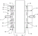
FIG. 1 is a front view of a fixture for machining a clump weight of an automobile transmission according to the present invention.
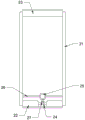
FIG. 2 is a top view of a fixture for machining a clump weight of an automobile transmission according to the present invention.
FIG. 3 is a schematic diagram of the internal structure of a conveyor belt of the fixture for processing the clump weight of the automobile gearbox.
Description of the drawings: 1. the device comprises a table board, 2, supporting legs, 3, a transverse plate, 4, an electric push rod, 5, a supporting plate, 6, a supporting rod, 7, a first air cylinder, 8, a second air cylinder, 9, a first movable plate, 10, a second movable plate, 11, a first slide block, 12, a second slide block, 13, a first guide groove, 14, a second guide groove, 15, a first rotary disc, 16, a second rotary disc, 17, a first gear, 18, a first motor, 19, a rotating shaft, 20, a second gear, 21, a frame body, 22, a driving roller, 23, a driven roller, 24, a third gear, 25, a second motor, 26, a fixing rod, 27, a fourth gear, 28 and a connecting sheet.
Detailed Description
The present invention will be described in further detail with reference to the accompanying drawings.
With reference to the attached drawings, the clamp for machining the counterweight block of the automobile gearbox comprises a table top 1, wherein supporting legs 2 are arranged on the lower end face of the table top 1, a conveying belt is arranged above the table top 1, transverse plates 3 are arranged between the supporting legs 2, electric push rods 4 are arranged on the transverse plates 3, supporting plates 5 are arranged on piston rods of the electric push rods 4, supporting rods 6 are arranged on the supporting plates 5, the supporting rods 6 are connected with the table top 1 in a sliding mode, the supporting rods 6 are connected with the conveying belt, a first air cylinder 7 and a second air cylinder 8 are respectively arranged on the left side and the right side of the upper end face of the table top 1, a first movable plate 9 and a second movable plate 10 are respectively arranged on the left side and the right side of the conveying belt, a piston rod of the first air cylinder 7 is connected with the first movable plate 9, a, the utility model discloses a table top, including mesa 1, terminal surface conveyer belt, including the first conveyer belt of top surface, the first conveyer belt left and right sides of mesa 1 is equipped with guide way 13 and guide way two 14 respectively, slider 11 and slider two 12 respectively with guide way 13 and guide way two 14 sliding connection, the one side upper end that the first 9 of fly leaf is relative with two 10 of fly leaf evenly rotates respectively and is connected with carousel 15 and carousel two 16, the first 9 left surface upper end of fly leaf is equipped with to rotate and is connected with gear 17, gear 17 is connected with carousel 15, the first 9 left surface front end of fly leaf is equipped with motor 18, be equipped with pivot 19 on the output of motor 18, be equipped with gear two 20 in the pivot 19, gear two 20 meshes with gear 17.
The conveyer belt includes framework 21, drive roll 22 and driven voller 23, both ends are rotated around the framework 21 and are connected with drive roll 22 and driven voller 23, be equipped with three 24 of gears on the drive roll 22, the drive roll 22 rear side is equipped with two 25 of motors between the framework 21, two 25 of motors pass through dead lever 26 and are connected with framework 21, be equipped with four 27 of gears on two 25's the output, four 27 and three 24 meshing of gear, the overcoat of drive roll 22 and driven voller 23 is equipped with the belt.
Two groups of guide grooves I13 and sliding blocks I11, and two groups of guide grooves II 14 and sliding blocks II 10 are arranged.
The first motor 18 is a servo motor.
The rear side of the left side surface of the first movable plate 9 is provided with a connecting sheet 28, and the rotating shaft 19 is rotatably connected with the connecting sheet 28.
The working principle of the invention is as follows: when the clamp for processing the automobile gearbox balancing weight is used, the gearbox balancing weight is placed on a conveyor belt, the conveyor belt conveys the gearbox balancing weight, piston rods of a first air cylinder and a second air cylinder extend out to drive a first movable plate and a second movable plate to move relatively, a first sliding block is matched with a first guide groove to guide the movement direction of the first movable plate, a second sliding block is matched with a second guide groove to guide the movement direction of the second movable plate, a first rotating disc and a second rotating disc on the first movable plate and the second movable plate clamp the gearbox balancing weight tightly, a piston rod of an electric push rod retracts, the height of the conveyor belt is reduced, a first motor rotates to drive a rotating shaft to rotate, the first rotating disc is driven to rotate through the meshing of a first gear and a second gear, the angle of the gearbox balancing weight is further adjusted, after the machining is completed, the piston rod of the, the first rotating disc and the second rotating disc do not clamp the gearbox accessories any more, and the gearbox balancing weight is conveyed by the conveying belt.
The present invention and its embodiments have been described, without limitation, and the embodiments shown in the drawings are only one embodiment of the present invention and the actual configuration is not limited thereto. In summary, those skilled in the art should appreciate that they can readily use the disclosed conception and specific embodiments as a basis for designing or modifying other structures for carrying out the same purposes of the present invention without departing from the spirit and scope of the invention as defined by the appended claims.
Claims (5)
1. The utility model provides a processing motor transmission balancing weight's anchor clamps, includes mesa (1), the terminal surface is equipped with supporting leg (2) under mesa (1), its characterized in that: the table top is characterized in that a conveying belt is arranged above the table top (1), a transverse plate (3) is arranged between the supporting legs (2), an electric push rod (4) is arranged on the transverse plate (3), a supporting plate (5) is arranged on a piston rod of the electric push rod (4), a supporting rod (6) is arranged on the supporting plate (5), the supporting rod (6) is in sliding connection with the table top (1), the supporting rod (6) is connected with the conveying belt, a first air cylinder (7) and a second air cylinder (8) are respectively arranged on the left side and the right side of the upper end face of the table top (1), a first movable plate (9) and a second movable plate (10) are respectively arranged on the left side and the right side of the conveying belt, a first air cylinder (7) piston rod is connected with the first movable plate (9), a second air cylinder (8) piston rod is connected with the second movable plate (10), a, the utility model discloses a table top, including mesa (1), top surface conveyer belt left and right sides, slider (11) and slider (12) are equipped with guide way (13) and guide way two (14) respectively, slider (11) and slider two (12) respectively with guide way (13) and guide way two (14) sliding connection, even rotation is connected with carousel (15) and carousel two (16) respectively in the relative one side upper end of fly leaf (9) and fly leaf two (10), fly leaf (9) left surface upper end is equipped with to rotate and is connected with gear (17), gear (17) are connected with carousel (15), fly leaf (9) left surface front end is equipped with motor (18), be equipped with pivot (19) on the output of motor (18), be equipped with gear two (20) on pivot (19), gear two (20) and gear (17) meshing.
2. The clamp for machining the clump weight of the automobile gearbox as claimed in claim 1, wherein: the conveyer belt includes framework (21), drive roll (22) and driven voller (23), both ends are rotated around framework (21) and are connected with drive roll (22) and driven voller (23), be equipped with three (24) of gear on drive roll (22), drive roll (22) rear side is equipped with motor two (25) between framework (21), motor two (25) are connected with framework (21) through dead lever (26), be equipped with four (27) of gear on the output of motor two (25), four (27) of gear and three (24) meshing of gear, drive roll (22) and driven voller (23) overcoat are equipped with the belt.
3. The clamp for machining the clump weight of the automobile gearbox as claimed in claim 1, wherein: two groups of guide grooves I (13) and sliding blocks I (11) and two groups of guide grooves II (14) and sliding blocks II (10) are arranged.
4. The clamp for machining the clump weight of the automobile gearbox as claimed in claim 1, wherein: the first motor (18) adopts a servo motor.
5. The clamp for machining the clump weight of the automobile gearbox as claimed in claim 1, wherein: the rear side of the left side face of the movable plate I (9) is provided with a connecting sheet (28), and the rotating shaft (19) is rotatably connected with the connecting sheet (28).
Priority Applications (1)
| Application Number | Priority Date | Filing Date | Title |
|---|---|---|---|
| CN202010877750.2A CN112141687A (en) | 2020-08-27 | 2020-08-27 | Clamp for machining counterweight block of automobile gearbox |
Applications Claiming Priority (1)
| Application Number | Priority Date | Filing Date | Title |
|---|---|---|---|
| CN202010877750.2A CN112141687A (en) | 2020-08-27 | 2020-08-27 | Clamp for machining counterweight block of automobile gearbox |
Publications (1)
| Publication Number | Publication Date |
|---|---|
| CN112141687A true CN112141687A (en) | 2020-12-29 |
Family
ID=73887767
Family Applications (1)
| Application Number | Title | Priority Date | Filing Date |
|---|---|---|---|
| CN202010877750.2A Pending CN112141687A (en) | 2020-08-27 | 2020-08-27 | Clamp for machining counterweight block of automobile gearbox |
Country Status (1)
| Country | Link |
|---|---|
| CN (1) | CN112141687A (en) |
Cited By (1)
| Publication number | Priority date | Publication date | Assignee | Title |
|---|---|---|---|---|
| CN112974619A (en) * | 2021-03-24 | 2021-06-18 | 浙江索迪电器有限公司 | Automatic material conveying and receiving machine device |
Citations (8)
| Publication number | Priority date | Publication date | Assignee | Title |
|---|---|---|---|---|
| JPH07144100A (en) * | 1993-11-24 | 1995-06-06 | Nippon Steel Kk | Empty hanger continuous feeder |
| CN205873089U (en) * | 2016-07-06 | 2017-01-11 | 白美程 | Special transport vechicle in library |
| CN207070467U (en) * | 2017-08-31 | 2018-03-02 | 铜陵安博电路板有限公司 | Pcb board automatic turnover device |
| CN208135392U (en) * | 2018-03-27 | 2018-11-23 | 长兴宇通机械厂 | Turnover device is used in a kind of production of refractory material |
| CN208182058U (en) * | 2018-03-28 | 2018-12-04 | 漳州龙文维克信息技术有限公司 | A kind of industrial production transmission device |
| CN110193810A (en) * | 2019-06-12 | 2019-09-03 | 长江师范学院 | A kind of dedicated tipping arrangement of mechanical and electric equipment installation |
| CN210029038U (en) * | 2019-06-06 | 2020-02-07 | 铁岭宇川精密机械制造有限公司 | Conveyor for machining |
| CN210790374U (en) * | 2019-11-13 | 2020-06-19 | 上饶市星火光电有限公司 | Clamping device for grinding optical lens |
-
2020
- 2020-08-27 CN CN202010877750.2A patent/CN112141687A/en active Pending
Patent Citations (8)
| Publication number | Priority date | Publication date | Assignee | Title |
|---|---|---|---|---|
| JPH07144100A (en) * | 1993-11-24 | 1995-06-06 | Nippon Steel Kk | Empty hanger continuous feeder |
| CN205873089U (en) * | 2016-07-06 | 2017-01-11 | 白美程 | Special transport vechicle in library |
| CN207070467U (en) * | 2017-08-31 | 2018-03-02 | 铜陵安博电路板有限公司 | Pcb board automatic turnover device |
| CN208135392U (en) * | 2018-03-27 | 2018-11-23 | 长兴宇通机械厂 | Turnover device is used in a kind of production of refractory material |
| CN208182058U (en) * | 2018-03-28 | 2018-12-04 | 漳州龙文维克信息技术有限公司 | A kind of industrial production transmission device |
| CN210029038U (en) * | 2019-06-06 | 2020-02-07 | 铁岭宇川精密机械制造有限公司 | Conveyor for machining |
| CN110193810A (en) * | 2019-06-12 | 2019-09-03 | 长江师范学院 | A kind of dedicated tipping arrangement of mechanical and electric equipment installation |
| CN210790374U (en) * | 2019-11-13 | 2020-06-19 | 上饶市星火光电有限公司 | Clamping device for grinding optical lens |
Cited By (1)
| Publication number | Priority date | Publication date | Assignee | Title |
|---|---|---|---|---|
| CN112974619A (en) * | 2021-03-24 | 2021-06-18 | 浙江索迪电器有限公司 | Automatic material conveying and receiving machine device |
Similar Documents
| Publication | Publication Date | Title |
|---|---|---|
| CN220162010U (en) | Plank grinding device of action of polishing of simulation manual work | |
| WO2021196479A1 (en) | Lifting device and apparatus | |
| CN216464433U (en) | Mechanical design is with assembly bench that has guide structure | |
| CN111570581A (en) | A freely combinable flexible bending center | |
| CN223114713U (en) | Auxiliary turning device for machining mechanical parts | |
| CN221158342U (en) | Back stop device for bending machine | |
| CN216991955U (en) | Mechanical arm | |
| CN222037235U (en) | A metal material welding robot | |
| CN113580118A (en) | Injection molding machine operation manipulator and telescoping device thereof | |
| CN112024182A (en) | Automatic turnover device for spraying of automobile balance block | |
| CN114310811B (en) | A workpiece turning mechanism | |
| CN217618864U (en) | Translation tilting mechanism of work piece | |
| CN113733076B (en) | Leather grabbing mechanical arm | |
| CN108856378B (en) | Back stop device for bending machine | |
| CN211965801U (en) | A compact press feeding automation device | |
| CN222495483U (en) | Conveyer belt with follow and press function | |
| CN222820711U (en) | A multifunctional roller conveyor | |
| CN222327440U (en) | Turnover device for mechanical automatic production and processing | |
| CN114260929A (en) | Multi-angle grabbing mechanical device based on automatic robot | |
| CN223849933U (en) | A mobile platform for easy material transfer in a blow molding machine | |
| CN219705241U (en) | Adsorption type PCB transfer and installation mechanical arm | |
| CN223802228U (en) | An automated trimming device for aluminum processing | |
| CN216329995U (en) | Variable pitch device of bottle blowing machine | |
| CN220946867U (en) | Press with adjust supporting seat | |
| CN223051071U (en) | Bending detection device for plastic suction tray |
Legal Events
| Date | Code | Title | Description |
|---|---|---|---|
| PB01 | Publication | ||
| PB01 | Publication | ||
| SE01 | Entry into force of request for substantive examination | ||
| SE01 | Entry into force of request for substantive examination | ||
| WD01 | Invention patent application deemed withdrawn after publication |
Application publication date: 20201229 |
|
| WD01 | Invention patent application deemed withdrawn after publication |