CN112139657A - Full-automatic friction welding machine - Google Patents
Full-automatic friction welding machine Download PDFInfo
- Publication number
- CN112139657A CN112139657A CN202011162953.XA CN202011162953A CN112139657A CN 112139657 A CN112139657 A CN 112139657A CN 202011162953 A CN202011162953 A CN 202011162953A CN 112139657 A CN112139657 A CN 112139657A
- Authority
- CN
- China
- Prior art keywords
- chuck
- cylinder
- movable chuck
- jacking
- lathe
- Prior art date
- Legal status (The legal status is an assumption and is not a legal conclusion. Google has not performed a legal analysis and makes no representation as to the accuracy of the status listed.)
- Granted
Links
- 238000003466 welding Methods 0.000 title claims abstract description 28
- 238000006073 displacement reaction Methods 0.000 claims abstract description 15
- 230000000694 effects Effects 0.000 claims description 5
- 238000007790 scraping Methods 0.000 claims description 3
- 208000032544 Cicatrix Diseases 0.000 claims description 2
- 231100000241 scar Toxicity 0.000 claims description 2
- 230000037387 scars Effects 0.000 claims description 2
- 238000003825 pressing Methods 0.000 abstract description 20
- 238000004519 manufacturing process Methods 0.000 abstract description 5
- 238000000034 method Methods 0.000 description 5
- 230000008569 process Effects 0.000 description 4
- 230000009471 action Effects 0.000 description 2
- 230000009286 beneficial effect Effects 0.000 description 2
- 230000008859 change Effects 0.000 description 2
- 239000000463 material Substances 0.000 description 2
- 238000002485 combustion reaction Methods 0.000 description 1
- 238000001514 detection method Methods 0.000 description 1
- 238000003754 machining Methods 0.000 description 1
- 230000009467 reduction Effects 0.000 description 1
- 239000007787 solid Substances 0.000 description 1
Images


Classifications
-
- B—PERFORMING OPERATIONS; TRANSPORTING
- B23—MACHINE TOOLS; METAL-WORKING NOT OTHERWISE PROVIDED FOR
- B23K—SOLDERING OR UNSOLDERING; WELDING; CLADDING OR PLATING BY SOLDERING OR WELDING; CUTTING BY APPLYING HEAT LOCALLY, e.g. FLAME CUTTING; WORKING BY LASER BEAM
- B23K20/00—Non-electric welding by applying impact or other pressure, with or without the application of heat, e.g. cladding or plating
- B23K20/12—Non-electric welding by applying impact or other pressure, with or without the application of heat, e.g. cladding or plating the heat being generated by friction; Friction welding
- B23K20/122—Non-electric welding by applying impact or other pressure, with or without the application of heat, e.g. cladding or plating the heat being generated by friction; Friction welding using a non-consumable tool, e.g. friction stir welding
-
- B—PERFORMING OPERATIONS; TRANSPORTING
- B23—MACHINE TOOLS; METAL-WORKING NOT OTHERWISE PROVIDED FOR
- B23K—SOLDERING OR UNSOLDERING; WELDING; CLADDING OR PLATING BY SOLDERING OR WELDING; CUTTING BY APPLYING HEAT LOCALLY, e.g. FLAME CUTTING; WORKING BY LASER BEAM
- B23K20/00—Non-electric welding by applying impact or other pressure, with or without the application of heat, e.g. cladding or plating
- B23K20/26—Auxiliary equipment
Landscapes
- Engineering & Computer Science (AREA)
- Mechanical Engineering (AREA)
- Pressure Welding/Diffusion-Bonding (AREA)
Abstract
Full-automatic friction welding machine relates to the welding technology field, it includes the lathe, be equipped with fixed chuck and movable chuck on the lathe, the central axis of fixed chuck and movable chuck is aligned, fixed chuck is connected with and is used for driving its pivoted motor, install the hydro-cylinder that is used for driving movable chuck along its axial displacement on the lathe, the rear end fixedly connected with roof pressure cylinder of movable chuck, be equipped with the contained angle between the central axis of roof pressure cylinder piston rod and the central axis of movable chuck, the one end fixedly connected with top pressing piece of roof pressure cylinder piston rod, one side of top pressing piece is equipped with the roof pressure face perpendicular with the central axis of movable chuck, the roof pressure cylinder can drive the slant of roof pressure piece and make the roof pressure face support and lean on the rear end in the second work piece, still be equipped with the lathe tool that is used for striking off the crater. The invention realizes automatic and high-precision jacking and positioning on the workpiece, thereby improving the production efficiency and the product quality.
Description
Technical Field
The invention relates to the technical field of welding, in particular to a full-automatic friction welding machine.
Background
Friction welding is a solid state welding method. The friction welding machine uses friction heat as energy, and generates heat on the friction surfaces of two weldments through mechanical friction movement and axial pressure, so that the friction surfaces of the two weldments are heated to plastic deformation, and then the two weldments made of the same material or different materials are firmly connected by utilizing the plastic deformation.
When two rod pieces (such as an internal combustion engine air valve) are welded by an existing friction welding machine, the two rod pieces are generally fixed by two chucks respectively, friction surfaces of the two rod pieces are contacted, one chuck of the two chucks is rotated to enable the rod pieces to rotate at a high speed so as to realize welding, one end of the rod piece clamped by the other chuck needs to be subjected to jacking positioning, an adjusting bolt is arranged at the rear end of the rod piece in a traditional jacking positioning mode, after the rod piece is inserted into the chuck and abutted against the other rod piece, the adjusting bolt is rotated, the head of the adjusting bolt is abutted against the rod piece so as to finish jacking positioning, the positioning mode is troublesome, large labor force of workers is consumed, and the production efficiency is low. Moreover, because adjusting bolt is from the screw hole toward the extroversion realize top pressure member end, when adjusting bolt's part was too much when being in the screw hole outside, can face two problems, firstly can produce certain deviation with the concentricity between the member, and then influence the precision of location, secondly because the less part of adjusting bolt is stayed in the screw hole for the top pressure stability in the course of working is not good, finally leads to the machining precision of product to reduce.
Disclosure of Invention
The invention aims to provide a full-automatic friction welding machine, which is used for realizing automatic and high-precision jacking positioning on a workpiece, thereby improving the production efficiency and the product quality.
In order to solve the technical problems, the invention adopts the following technical scheme: a full-automatic friction welding machine comprises a machine tool, wherein a fixed chuck and a movable chuck are arranged on the machine tool, the fixed chuck is used for clamping a first workpiece, the movable chuck is used for clamping a second workpiece, the central axes of the fixed chuck and the movable chuck are aligned, the fixed chuck is connected with a motor used for driving the fixed chuck to rotate, an oil cylinder used for driving the movable chuck to move axially is mounted on the machine tool, a jacking cylinder is fixedly connected to the rear end of the movable chuck, an included angle is formed between the central axis of a piston rod of the jacking cylinder and the central axis of the movable chuck, one end of the piston rod of the jacking cylinder is fixedly connected with a jacking block, a jacking surface perpendicular to the central axis of the movable chuck is arranged on one side of the jacking block, the jacking cylinder can drive the jacking block to move obliquely and enable the jacking surface to abut against the rear end of the second workpiece, and a turning tool used for scraping welding scars is, and a turning tool cylinder for driving a turning tool to move along the vertical direction of the axis of the first workpiece is arranged on the machine tool.
Preferably, a pressure gauge for detecting the pressure of the oil cylinder is mounted on the machine tool.
Or preferably, a displacement sensor for detecting the moving distance of the movable chuck is mounted on the movable chuck.
More preferably, a first slide rail is installed on the machine tool along the axial direction of the movable chuck, a first slide seat is connected to the first slide rail in a sliding manner, and the movable chuck and the jacking cylinder are both fixedly connected to the first slide seat.
More preferably, the front end of the movable chuck is fixedly connected with a connecting plate, the number of the oil cylinders is two, the two oil cylinders are respectively installed on the machine tools on the two sides of the fixed chuck, and one end of a piston rod of each oil cylinder is fixedly connected with the connecting plate.
More preferably, be equipped with the second slide on the lathe, the bottom of second slide is connected with the second slide rail, lathe tool fixed mounting is on the second slide, the second slide is connected to the one end of lathe tool cylinder piston rod.
More preferably, a control cabinet is arranged on the machine tool, and a control panel is arranged on the control cabinet.
The invention has the beneficial effects that: after a first workpiece is arranged in the fixed chuck, a second workpiece is arranged in the movable chuck and pre-abuts against the first workpiece, then the jacking cylinder can be started, so that the jacking block moves obliquely, when the jacking surface of the jacking block abuts against the rear end of the second workpiece, the jacking cylinder can stop moving and keep the jacking block in a jacking state, then the motor drives the fixed chuck to rotate at a high speed, so that the first workpiece can be driven to rotate at a high speed, the welding operation with the second workpiece is realized, in the welding process, the jacking block keeps the jacking state of the second workpiece, so that the second workpiece and the first workpiece can have better concentricity, the second workpiece has better stability, the processing quality of products is effectively improved, and the labor force is greatly reduced in the mode that the jacking cylinder drives the jacking block to jack and position the second workpiece, and improves the production efficiency.
Drawings
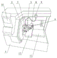
Fig. 1 is a schematic view of the overall structure in embodiment 1 of the present invention;
FIG. 2 is a schematic top view of the structure of the fixed chuck and the movable chuck in embodiment 1;
FIG. 3 is a schematic side view of the structure of the fixed chuck and the movable chuck in embodiment 1;
FIG. 4 is a schematic view of the overall structure in embodiment 2 of the present invention
Fig. 5 is a schematic top view of the structure of the fixed chuck and the movable chuck in accordance with embodiment 2 of the present invention.
The reference signs are:
1-machine tool 2-fixed chuck 3-movable chuck
4 a-first workpiece 4 b-second workpiece 5-oil cylinder
6-top pressure cylinder 6 a-top pressure block 6 b-top pressure surface
7-turning tool 8-turning tool cylinder 9-pressure gauge
10-displacement sensor 11-first slide rail 12-first slide carriage
13-connecting plate 14-second slide carriage 15-control panel.
Detailed Description
In order to facilitate understanding of those skilled in the art, the present invention will be further described with reference to the following examples and drawings, which are not intended to limit the present invention.
It should be noted that, unless otherwise explicitly stated or limited, the terms "mounted," "connected," "fixed," and the like are used broadly in the present invention, and may be, for example, fixedly connected, detachably connected, or integrally connected; they may be connected directly or indirectly through intervening media, or they may be interconnected between two elements. The specific meanings of the above terms in the present invention can be understood by those skilled in the art according to specific situations.
Further, in the present invention, unless otherwise expressly specified or limited, the first feature "on" or "under" the second feature may comprise the first and second features being in direct contact, or may comprise the first and second features being in contact, not in direct contact, but via another feature in between. Also, the first feature being "on," "above" and "over" the second feature includes the first feature being directly on and obliquely above the second feature, or merely indicating that the first feature is at a higher level than the second feature. A first feature being "under," "below," and "beneath" a second feature includes the first feature being directly under and obliquely below the second feature, or simply meaning that the first feature is at a lesser elevation than the second feature. The terms "upper", "lower", "front", "rear", "left", "right", "vertical", "horizontal", "top", "bottom", "inner", "outer", and the like, indicate orientations or positional relationships based on those shown in the drawings, and are only for convenience in describing and simplifying the description, but do not indicate or imply that the device or element referred to must have a particular orientation, be constructed and operated in a particular orientation, and thus, should not be construed as limiting the invention.
Example 1
As shown in fig. 1-3, the full-automatic friction welding machine comprises a machine tool 1, wherein a fixed chuck 2 for clamping a first workpiece 4a and a movable chuck 3 for clamping a second workpiece 4b are arranged on the machine tool 1, central axes of the fixed chuck 2 and the movable chuck 3 are aligned, the fixed chuck 2 is connected with a motor (not shown in the drawing) for driving the fixed chuck to rotate, an oil cylinder 5 for driving the movable chuck 3 to move axially is arranged on the machine tool 1, a jacking cylinder 6 is fixedly connected to a rear end of the movable chuck 3, an included angle is formed between a central axis of a piston rod of the jacking cylinder 6 and a central axis of the movable chuck 3, one end of the piston rod of the jacking cylinder 6 is fixedly connected with a jacking block 6a, a jacking surface 6b perpendicular to the central axis of the movable chuck 3 is arranged on one side of the jacking block 6a, the jacking cylinder 6 can drive the jacking block 6a to move obliquely and enable the jacking surface 6b to abut against the rear end of, a turning tool 7 for scraping the crater is further arranged between the fixed chuck 2 and the movable chuck 3, and a turning tool cylinder 8 for driving the turning tool 7 to move along the vertical direction of the axis of the first workpiece 4a is arranged on the machine tool 1.
Before the full-automatic friction welding machine provided by the above embodiment starts to work, the feeding is performed first, because the length of the second workpiece 4b in the blank processed in this embodiment is greater than the length of the first workpiece 4a, the first workpiece 4a can be inserted from the rear end of the movable chuck 3, then the second workpiece 4b can be inserted into the movable chuck 3 and push the first workpiece 4a forward, so that the first workpiece 4a is pushed into the fixed chuck 2 (the two chucks are not far apart), at this time, the fixed chuck 2 can clamp the first workpiece 4a, then the pressing cylinder 6 is started, so that the pressing block 6a moves obliquely, until the pressing surface 6b of the pressing block 6a presses against the rear end of the second workpiece 4b, the pressing cylinder 6 can stop moving and the pressing block 6a is kept in a pressing state, and then the motor drives the fixed chuck 2 to rotate at a high speed, thereby can drive first work piece 4a high-speed rotation, in the high-speed pivoted of first work piece 4a, hydro-cylinder 5 drive activity chuck 3 is slowly close to toward the direction of fixed chuck 2, in order to realize with the welding operation of second work piece 4b, the welding is preliminary accomplished, can form high temperature crater between two work pieces, then the motor stop work, hydro-cylinder 5 drive activity chuck 3 removes in the direction of fixed chuck 2 once more in order to make the roof impact action, thereby fully extrude the unnecessary crater between two work pieces, then can start motor and lathe tool cylinder 8 simultaneously, thereby make lathe tool 7 be close to between two work pieces and strike off the crater totally, the work of friction welding can be accomplished.
In the welding process, the jacking block 6a keeps a jacking state on the second workpiece 4b, so that the second workpiece 4b and the first workpiece 4a can have better concentricity, the second workpiece 4b has better stability, the processing quality of a product is effectively improved, and the jacking cylinder 6 drives the jacking block 6a to jack and position the second workpiece 4b, so that the labor force of workers is greatly reduced, and the production efficiency is improved.
It should be noted that, as will be understood by those skilled in the art, the fixed chuck 2 and the movable chuck 3 in the above embodiments are common chucks in the prior art, and both have a function of clamping a workpiece, so that the specific structure of the chuck is not described in detail.
Preferably, a pressure gauge 9 for detecting the pressure of the cylinder 5 is installed on the machine tool 1, and since the cylinder 5 needs to be started twice during the welding operation, one pressure gauge 9 is provided, so that an operator can recognize whether the cylinder 5 normally works by observing the change of the pressure gauge 9, and thus can determine that the second workpiece 4b has performed normal secondary movement, because the length of the workpiece after welding can be shortened to a certain extent, and the length of the second workpiece 4b can be shortened by two times of butting processes, it is necessary to determine whether the second workpiece 4b has performed secondary movement, and it is a convenient and low-cost way by observing the change of the pressure gauge 9.
More preferably, a first slide rail 11 is mounted on the machine tool 1 along the axial direction of the movable chuck 3, a first slide 12 is slidably connected to the first slide rail 11, and both the movable chuck 3 and the jacking cylinder 6 are fixedly connected to the first slide 12.
More preferably, the front end of the movable chuck 3 is fixedly connected with a connecting plate 13, the number of the oil cylinders 5 is two, the two oil cylinders 5 are respectively installed on the machine tool 1 at two sides of the fixed chuck 2, one end of a piston rod of each oil cylinder 5 is fixedly connected with the connecting plate 13, and the two oil cylinders 5 drive the movable chuck 3 to move, so that the moving process can be more stable.
More preferably, the machine tool 1 is provided with a second slide seat 14, the bottom of the second slide seat 14 is connected with a second slide rail, the turning tool 7 is fixedly mounted on the second slide seat 14, one end of a piston rod of the turning tool cylinder 8 is connected with the second slide seat 14, and the turning tool cylinder 8 pushes the second slide seat 14 to make the turning tool 7 move, so that the feeding and retracting actions of the turning tool 7 can be more stable.
More preferably, the length of the pressing surface 6b is greater than twice the length of the outer diameter of the second workpiece 4b, when the pressing cylinder 6 pushes the pressing block 6a to move obliquely, the pressing surface 6b moves obliquely in a posture perpendicular to the central axis of the movable chuck 3, so that when the pressing surface 6b contacts the rear end surface of the second workpiece 4b, the pressing surface 6b has actually moved a certain distance, and therefore, in order to ensure that the pressing surface 6b can be in pressing and positioning contact with the rear end surface of the second workpiece 4b, the pressing surface 6b needs to have a certain length, which is greater than twice the length of the outer diameter of the second workpiece 4b in this embodiment, so that the middle of the pressing surface 6b can be pressed against the rear end surface of the second workpiece 4b after the pressing block 6a moves a certain distance, and the stability is better.
More preferably, the included angle between the central axis of the piston rod of the jacking cylinder 6 and the central axis of the movable chuck 3 is 75 degrees.
In addition, in this embodiment, the control cabinet is arranged on the machine tool 1, and the control panel 15 is arranged on the control cabinet, so that an operator can conveniently operate and control each component in the machine tool 1 from the control panel 15.
Example 2
As shown in fig. 4 to 5, the present embodiment differs from embodiment 1 only in the manner of determining whether the second workpiece 4b normally undergoes two displacements, and solves this problem by mounting a displacement sensor 10 for detecting the moving distance thereof on the movable chuck 3, as compared to the manner of embodiment 1 in which the operator observes the pressure gauge 9. Of course, it should be understood by those skilled in the art that the machine tool of the present embodiment further includes a controller and other components to connect the displacement sensor 10, so that when the displacement sensor 10 sends displacement data to the controller, it can be determined that the second workpiece 4b is displaced normally, i.e. the length reduction phenomenon caused by welding occurs, so that the machine tool 1 can continue to operate normally, which is beneficial to replace the way of observing the pressure gauge 9, and greatly reduce the labor intensity of the worker and the possibility of misoperation of the worker. Since the first workpiece 4a and the second workpiece 4b are in gapless contact in the initial state, accurate displacement friction welding can be realized by using the displacement sensor, and the reliability of the processing quality is ensured.
In addition, more specifically, the displacement sensor 10 in the present embodiment may be provided on the first carriage 12 so that the detection of the displacement data is more accurate, and the displacement sensor 10 may be a stay-type displacement sensor, and a fixed end of the stay may be mounted on a wall surface of the machine tool 1 (as shown in fig. 5).
The above embodiments are preferred implementations of the present invention, and the present invention can be implemented in other ways without departing from the spirit of the present invention.
Some of the drawings and descriptions of the present invention have been simplified to facilitate the understanding of the improvements over the prior art by those skilled in the art, and some other elements have been omitted from this document for the sake of clarity, and it should be appreciated by those skilled in the art that such omitted elements may also constitute the subject matter of the present invention.
Claims (7)
1. Full-automatic friction welding machine, including lathe (1), be equipped with on lathe (1) and be used for the fixed chuck (2) of centre gripping first work piece (4 a) and be used for the activity chuck (3) of centre gripping second work piece (4 b), the central axis of fixed chuck (2) and activity chuck (3) is aligned, its characterized in that: the fixed chuck (2) is connected with a motor for driving the fixed chuck to rotate, an oil cylinder (5) for driving the movable chuck (3) to move axially is mounted on the machine tool (1), a jacking cylinder (6) is fixedly connected to the rear end of the movable chuck (3), an included angle is formed between the central axis of a piston rod of the jacking cylinder (6) and the central axis of the movable chuck (3), one end of the piston rod of the jacking cylinder (6) is fixedly connected with a jacking block (6 a), a jacking surface (6 b) perpendicular to the central axis of the movable chuck (3) is arranged on one side of the jacking block (6 a), the jacking cylinder (6) can drive the jacking block (6 a) to move obliquely and enable the jacking surface (6 b) to abut against the rear end of a second workpiece (4 b), and a turning tool (7) for scraping welding scars is further arranged between the fixed chuck (2) and the movable chuck (3), and a turning tool cylinder (8) for driving the turning tool (7) to move along the vertical direction of the axis of the first workpiece (4 a) is arranged on the machine tool (1).
2. The fully automatic friction welder according to claim 1, characterized in that: and a pressure gauge (9) for detecting the pressure of the oil cylinder (5) is arranged on the machine tool (1).
3. The fully automatic friction welder according to claim 1, characterized in that: and a displacement sensor (10) for detecting the moving distance of the movable chuck (3) is arranged on the movable chuck.
4. The full automatic friction welder according to claim 2 or 3, characterized in that: the automatic clamping device is characterized in that a first sliding rail (11) is installed on the machine tool (1) along the axial direction of the movable chuck (3), a first sliding seat (12) is connected onto the first sliding rail (11) in a sliding mode, and the movable chuck (3) and the jacking cylinder (6) are fixedly connected onto the first sliding seat (12).
5. The fully automatic friction welder according to claim 4, characterized in that: the front end fixedly connected with connecting plate (13) of activity chuck (3), the quantity of hydro-cylinder (5) is two, and two hydro-cylinders (5) are installed respectively on lathe (1) of fixed chuck (2) both sides, the one end and the connecting plate (13) fixed connection of hydro-cylinder (5) piston rod.
6. The fully automatic friction welder according to claim 5, characterized in that: be equipped with second slide (14) on lathe (1), the bottom of second slide (14) is connected with the second slide rail, lathe tool (7) fixed mounting is on second slide (14), second slide (14) are connected to the one end of lathe tool cylinder (8) piston rod.
7. The fully automatic friction welder according to claim 6, characterized in that: the machine tool (1) is provided with a control cabinet, and the control cabinet is provided with a control panel (15).
Priority Applications (1)
| Application Number | Priority Date | Filing Date | Title |
|---|---|---|---|
| CN202011162953.XA CN112139657B (en) | 2020-10-27 | 2020-10-27 | Full-automatic friction welding machine |
Applications Claiming Priority (1)
| Application Number | Priority Date | Filing Date | Title |
|---|---|---|---|
| CN202011162953.XA CN112139657B (en) | 2020-10-27 | 2020-10-27 | Full-automatic friction welding machine |
Publications (2)
| Publication Number | Publication Date |
|---|---|
| CN112139657A true CN112139657A (en) | 2020-12-29 |
| CN112139657B CN112139657B (en) | 2022-03-22 |
Family
ID=73953475
Family Applications (1)
| Application Number | Title | Priority Date | Filing Date |
|---|---|---|---|
| CN202011162953.XA Active CN112139657B (en) | 2020-10-27 | 2020-10-27 | Full-automatic friction welding machine |
Country Status (1)
| Country | Link |
|---|---|
| CN (1) | CN112139657B (en) |
Cited By (1)
| Publication number | Priority date | Publication date | Assignee | Title |
|---|---|---|---|---|
| CN115570257A (en) * | 2022-11-21 | 2023-01-06 | 德州联瑞科技有限公司 | Valve body processing welding equipment |
Citations (9)
| Publication number | Priority date | Publication date | Assignee | Title |
|---|---|---|---|---|
| SU1303333A1 (en) * | 1985-11-14 | 1987-04-15 | Челябинский конструкторско-технологический институт автоматизации и механизации в автомобилестроении | Clamping device |
| JP2001113379A (en) * | 1999-10-20 | 2001-04-24 | Nikki Denso Kk | Drawing type friction welding machine |
| JP2003245781A (en) * | 2002-02-20 | 2003-09-02 | Izumi Kogyo Kk | Friction welding method and equipment |
| CN204524539U (en) * | 2014-12-30 | 2015-08-05 | 陕西理工学院 | Complex function Continuous Drive Friction Welding machine |
| CN107414282A (en) * | 2017-06-23 | 2017-12-01 | 苏州西岩机械技术有限公司 | A kind of friction-welding machine gag lever post backlash eliminating equipment |
| CN109483041A (en) * | 2018-10-25 | 2019-03-19 | 哈尔滨焊接研究院有限公司 | Friction welding axial deflection accuracy control process |
| CN210115567U (en) * | 2019-05-17 | 2020-02-28 | 辽宁工业大学 | Friction welding machine capable of realizing no-leaving circular ring |
| CN111421273A (en) * | 2020-04-12 | 2020-07-17 | 陆建强 | Workpiece machining positioning static clamping mechanism for welding equipment |
| CN211029024U (en) * | 2019-10-08 | 2020-07-17 | 宁波大榭开发区华山机械有限公司 | Three-station positioning fixture for cylinder machining |
-
2020
- 2020-10-27 CN CN202011162953.XA patent/CN112139657B/en active Active
Patent Citations (9)
| Publication number | Priority date | Publication date | Assignee | Title |
|---|---|---|---|---|
| SU1303333A1 (en) * | 1985-11-14 | 1987-04-15 | Челябинский конструкторско-технологический институт автоматизации и механизации в автомобилестроении | Clamping device |
| JP2001113379A (en) * | 1999-10-20 | 2001-04-24 | Nikki Denso Kk | Drawing type friction welding machine |
| JP2003245781A (en) * | 2002-02-20 | 2003-09-02 | Izumi Kogyo Kk | Friction welding method and equipment |
| CN204524539U (en) * | 2014-12-30 | 2015-08-05 | 陕西理工学院 | Complex function Continuous Drive Friction Welding machine |
| CN107414282A (en) * | 2017-06-23 | 2017-12-01 | 苏州西岩机械技术有限公司 | A kind of friction-welding machine gag lever post backlash eliminating equipment |
| CN109483041A (en) * | 2018-10-25 | 2019-03-19 | 哈尔滨焊接研究院有限公司 | Friction welding axial deflection accuracy control process |
| CN210115567U (en) * | 2019-05-17 | 2020-02-28 | 辽宁工业大学 | Friction welding machine capable of realizing no-leaving circular ring |
| CN211029024U (en) * | 2019-10-08 | 2020-07-17 | 宁波大榭开发区华山机械有限公司 | Three-station positioning fixture for cylinder machining |
| CN111421273A (en) * | 2020-04-12 | 2020-07-17 | 陆建强 | Workpiece machining positioning static clamping mechanism for welding equipment |
Cited By (2)
| Publication number | Priority date | Publication date | Assignee | Title |
|---|---|---|---|---|
| CN115570257A (en) * | 2022-11-21 | 2023-01-06 | 德州联瑞科技有限公司 | Valve body processing welding equipment |
| CN115570257B (en) * | 2022-11-21 | 2023-03-10 | 德州联瑞科技有限公司 | Valve body processing welding equipment |
Also Published As
| Publication number | Publication date |
|---|---|
| CN112139657B (en) | 2022-03-22 |
Similar Documents
| Publication | Publication Date | Title |
|---|---|---|
| CN201603997U (en) | Novel drilling and riveting machine tool | |
| CN114346404B (en) | Friction welding equipment | |
| CN214080009U (en) | Welding platform with leveling head | |
| CN112139657B (en) | Full-automatic friction welding machine | |
| CN115283716B (en) | Automatic boring device for piston | |
| CN214322169U (en) | Full-automatic friction welding machine | |
| CN210908367U (en) | Double-end chamfering machine | |
| CN110202386B (en) | Welding device for transmission shaft | |
| CN108500428B (en) | Welding method for flame tube tile of aircraft engine | |
| CN212217437U (en) | Friction welding equipment | |
| CN214291903U (en) | Double-head electric-pushing numerical control type welding and turning combined friction welding machine | |
| CN211889980U (en) | Clamp for milling teeth of rack piston of automobile steering device | |
| CN221362721U (en) | Machine tool tailstock and machine tool | |
| CN101372078A (en) | Valve milling face tapping machine | |
| CN116748784B (en) | Flange type hydraulic cylinder body welding device | |
| CN210125887U (en) | Automatic centering machine tool center frame | |
| CN112059672A (en) | Commercial car oil tank fixed pin processing frock | |
| CN215967186U (en) | Turnover welding tool | |
| CN115338472B (en) | A high-precision horizontal broaching machine with a correction mechanism | |
| CN117020947A (en) | Workpiece jacking driving system and grinding machine using same | |
| CN112192080B (en) | A welding machine head for welding the inner ring of a steel cage and main reinforcement | |
| CN111014766B (en) | Motor shaft hole processing equipment | |
| CN213591857U (en) | Efficient mould steel milling machine | |
| CN211759858U (en) | Lathe hydraulic center frame capable of being operated in programmable mode | |
| CN213351184U (en) | Inclined cylinder tail positioning type chuck mechanism |
Legal Events
| Date | Code | Title | Description |
|---|---|---|---|
| PB01 | Publication | ||
| PB01 | Publication | ||
| SE01 | Entry into force of request for substantive examination | ||
| SE01 | Entry into force of request for substantive examination | ||
| GR01 | Patent grant | ||
| GR01 | Patent grant |