CN112137319A - Portable high-stability folding goods shelf - Google Patents
Portable high-stability folding goods shelf Download PDFInfo
- Publication number
- CN112137319A CN112137319A CN202011217807.2A CN202011217807A CN112137319A CN 112137319 A CN112137319 A CN 112137319A CN 202011217807 A CN202011217807 A CN 202011217807A CN 112137319 A CN112137319 A CN 112137319A
- Authority
- CN
- China
- Prior art keywords
- rod
- crossbar
- bracket
- screw
- telescopic hinge
- Prior art date
- Legal status (The legal status is an assumption and is not a legal conclusion. Google has not performed a legal analysis and makes no representation as to the accuracy of the status listed.)
- Pending
Links
- 238000011065 in-situ storage Methods 0.000 abstract 1
- 238000010586 diagram Methods 0.000 description 8
- 230000002787 reinforcement Effects 0.000 description 3
- 238000009434 installation Methods 0.000 description 2
- 238000004891 communication Methods 0.000 description 1
- 230000005484 gravity Effects 0.000 description 1
- 239000002184 metal Substances 0.000 description 1
- 238000000034 method Methods 0.000 description 1
- 238000012986 modification Methods 0.000 description 1
- 230000004048 modification Effects 0.000 description 1
- 238000003466 welding Methods 0.000 description 1
Images





Classifications
-
- A—HUMAN NECESSITIES
- A47—FURNITURE; DOMESTIC ARTICLES OR APPLIANCES; COFFEE MILLS; SPICE MILLS; SUCTION CLEANERS IN GENERAL
- A47B—TABLES; DESKS; OFFICE FURNITURE; CABINETS; DRAWERS; GENERAL DETAILS OF FURNITURE
- A47B81/00—Cabinets or racks specially adapted for other particular purposes, e.g. for storing guns or skis
-
- A—HUMAN NECESSITIES
- A47—FURNITURE; DOMESTIC ARTICLES OR APPLIANCES; COFFEE MILLS; SPICE MILLS; SUCTION CLEANERS IN GENERAL
- A47B—TABLES; DESKS; OFFICE FURNITURE; CABINETS; DRAWERS; GENERAL DETAILS OF FURNITURE
- A47B43/00—Cabinets, racks or shelf units, characterised by features enabling folding of the cabinet or the like
-
- A—HUMAN NECESSITIES
- A47—FURNITURE; DOMESTIC ARTICLES OR APPLIANCES; COFFEE MILLS; SPICE MILLS; SUCTION CLEANERS IN GENERAL
- A47B—TABLES; DESKS; OFFICE FURNITURE; CABINETS; DRAWERS; GENERAL DETAILS OF FURNITURE
- A47B47/00—Cabinets, racks or shelf units, characterised by features related to dismountability or building-up from elements
-
- A—HUMAN NECESSITIES
- A47—FURNITURE; DOMESTIC ARTICLES OR APPLIANCES; COFFEE MILLS; SPICE MILLS; SUCTION CLEANERS IN GENERAL
- A47B—TABLES; DESKS; OFFICE FURNITURE; CABINETS; DRAWERS; GENERAL DETAILS OF FURNITURE
- A47B97/00—Furniture or accessories for furniture, not provided for in other groups of this subclass
Landscapes
- Assembled Shelves (AREA)
Abstract
本发明公开了一种便携式高稳定性折叠货架,涉及便携货架领域,包括第一支架与第二支架。第一支架包括立杆、连接杆与折叠连杆;立杆包括A类立杆与B类立杆,所述两根A类立杆之间通过连接杆固定连接,两根B类立杆之间通过连接杆固定连接;A类立杆与B类立杆之间通过折叠连杆连接;所述折叠连杆包括第一横杆、第二横杆、双轴伸缩铰链与单轴伸缩铰链;第一横杆与第二横杆通过双轴伸缩铰链连接;第一横杆与A类立杆、第二横杆与B类立杆均分别通过单轴伸缩铰链连接。发明中第一支架采用横向折叠、就地装配的技术手段来减小占空性、增强运输能力,同时具备较快的装配速度,最终避免了现有技术中货架组装繁琐、展开后稳定性较差的不足之处。

The invention discloses a portable high-stability folding shelf, which relates to the field of portable shelves, comprising a first bracket and a second bracket. The first bracket includes a vertical rod, a connecting rod and a folding connecting rod; the vertical rod includes a type A vertical rod and a type B vertical rod, the two type A vertical rods are fixedly connected by a connecting rod, and the two type B vertical rods are fixedly connected. They are fixedly connected by connecting rods; the A-type vertical rods and the B-type vertical rods are connected by a folding link; the folding link includes a first crossbar, a second crossbar, a biaxial telescopic hinge and a single-axis telescopic hinge; The first crossbar and the second crossbar are connected by a double-axis telescopic hinge; the first crossbar and the A-type vertical rod, and the second crossbar and the B-type vertical rod are respectively connected by a single-axis telescopic hinge. In the invention, the first bracket adopts the technical means of horizontal folding and in-situ assembly to reduce the occupancy, enhance the transportation capacity, and at the same time have a relatively fast assembly speed, which ultimately avoids the cumbersome assembly of the shelves in the prior art and the relatively low stability after unfolding. Bad shortcoming.
Description
技术领域technical field
本发明涉及便携货架领域,具体为一种便携式高稳定性折叠货架。The invention relates to the field of portable shelves, in particular to a portable high-stability folding shelf.
背景技术Background technique
货架,即陈列、存放货物的架子,广泛应用于商城、仓库与居家。货架按发展分别分为:传统货架和新型货架。传统木质货架大多相对笨重,难以运输,且损耗率较高;传统金属货架则为了便于运输,通常到达使用地点后通过焊接成型,具有较大的污染且操作繁琐,因此,传统货架基本已被淘汰。新型货架包括:旋转式货架、移动式货架、穿梭车货架、装配式货架、调节式货架、托盘货架、进车式货架、高层货架、阁楼式货架、重力式货架、屏挂式货架等,其中,应用最为广泛的是装配式货架。Shelves, that is, shelves for displaying and storing goods, are widely used in shopping malls, warehouses and homes. The shelves are divided into traditional shelves and new shelves according to the development. Most traditional wooden shelves are relatively bulky, difficult to transport, and have a high loss rate; traditional metal shelves are usually formed by welding after arriving at the place of use in order to facilitate transportation, which has large pollution and cumbersome operations. Therefore, traditional shelves have basically been eliminated. . New types of shelves include: rotating shelves, mobile shelves, shuttle shelves, prefabricated shelves, adjustable shelves, pallet shelves, car-in shelves, high-rise shelves, attic shelves, gravity shelves, screen-mounted shelves, etc. , the most widely used is the prefabricated shelf.
装配式货架同样采用拆卸运输、就地组装的技术方案,极大提高了运输的便捷性,从一定程度上解决了传统货架运输困难的问题,但是依旧没有组装繁琐的不足之处。The prefabricated rack also adopts the technical solution of disassembly, transportation and on-site assembly, which greatly improves the convenience of transportation and solves the problem of difficult transportation of traditional racks to a certain extent, but it still does not have the disadvantage of cumbersome assembly.
折叠式货架通过采用机械结构的折叠方案来减小体积,来提高便捷性,但能够折叠/展开的机械结构具有相对较差的稳定性,因此折叠式货架展开安装后不仅容易晃动,而且载重能力降低。The foldable shelf reduces the volume by adopting the folding scheme of the mechanical structure to improve the convenience, but the mechanical structure that can be folded/unfolded has relatively poor stability, so the folding shelf is not only easy to shake after installation, but also the load capacity. reduce.
发明内容SUMMARY OF THE INVENTION
为了克服上述背景技术中现有货架组装繁琐、稳定性较差的不足之处,本发明提供了一种便携式高稳定性折叠货架。In order to overcome the above-mentioned disadvantages of complicated assembly and poor stability of the existing shelves in the background art, the present invention provides a portable high-stability folding shelf.
本发明解决上述不足之处所采用的技术方案是:一种便携式高稳定性折叠货架,包括第一支架与第二支架,第一支架上表面与第二支架下底面连接。The technical solution adopted by the present invention to solve the above shortcomings is: a portable high-stability folding shelf, comprising a first bracket and a second bracket, and the upper surface of the first bracket is connected with the lower bottom surface of the second bracket.
第一支架包括立杆、连接杆与折叠连杆;立杆包括至少两根A类立杆与至少两根B类立杆,所述两根A类立杆之间通过连接杆固定连接,两根B类立杆之间通过连接杆固定连接;A类立杆与B类立杆之间通过折叠连杆连接;所述折叠连杆包括第一横杆、第二横杆、双轴伸缩铰链与单轴伸缩铰链;第一横杆与第二横杆通过双轴伸缩铰链连接;单个双轴伸缩铰链与不少于两个第一螺丝、不少于两个第二螺丝均分别通过螺纹连接,第一横杆与第二横杆均分别设有第一条形孔,且第一螺丝分别位于第一条形孔内或第一条形孔正下方;第一横杆与双轴伸缩铰链、第二横杆与双轴伸缩铰链均分别通过第一螺丝的螺柱底端压接;第一横杆与A类立杆、第二横杆与B类立杆均分别通过单轴伸缩铰链连接;单个单轴伸缩铰链与不少于一个第三螺丝通过螺纹连接,第一横杆与第二横杆均分别设有第二条形孔,第三螺丝位于位于第二条形孔内或第二条形孔正下方;第一横杆与A类立杆、第二横杆与B类立杆均分别通过第三螺丝的螺柱底端压接。The first bracket includes a vertical rod, a connecting rod and a folding link; the vertical rod includes at least two A-type vertical rods and at least two B-type vertical rods, and the two A-type vertical rods are fixedly connected by connecting rods, and the two The B-type vertical rods are fixedly connected by connecting rods; the A-type vertical rods and the B-type vertical rods are connected by a folding link; the folding link includes a first cross rod, a second cross rod, and a biaxial telescopic hinge and uniaxial telescopic hinge; the first crossbar and the second crossbar are connected by a biaxial telescopic hinge; a single biaxial telescopic hinge is connected with no less than two first screws and no less than two second screws respectively through threads , the first crossbar and the second crossbar are respectively provided with a first bar-shaped hole, and the first screw is respectively located in the first bar-shaped hole or directly below the first bar-shaped hole; the first crossbar and the biaxial telescopic hinge , The second crossbar and the biaxial telescopic hinge are respectively crimped through the bottom end of the stud of the first screw; the first crossbar and the A-type vertical rod, the second crossbar and the B-type vertical rod are respectively connected by the single-axis telescopic hinge Connection; a single uniaxial telescopic hinge is connected with no less than one third screw through threads, the first crossbar and the second crossbar are respectively provided with second bar-shaped holes, and the third screw is located in the second bar-shaped hole or Just below the second strip hole; the first horizontal bar and the A-type vertical rod, the second horizontal bar and the B-type vertical rod are respectively crimped through the bottom end of the stud of the third screw.
第二支架包括不少于四个支撑杆与不少于四个内嵌式角连接件,且所述支撑杆首尾依次通过内嵌式角连接件连接成环形或U形;单个内嵌式角连接件与不少于两个第四螺丝通过螺纹连接;单根支撑杆两端分别设有通孔,所述第四螺丝位于通孔内或通孔正下方;所述支撑杆与内嵌式角连接件分别通过第四螺丝的螺柱底端压接。The second bracket includes no less than four support rods and no less than four built-in corner connectors, and the support rods are connected end to end in a ring or U shape through the built-in corner connectors; a single built-in corner The connecting piece is connected with no less than two fourth screws through threads; the two ends of the single support rod are respectively provided with through holes, and the fourth screw is located in the through hole or right below the through hole; the support rod is connected to the embedded type The corner connectors are respectively crimped through the bottom ends of the studs of the fourth screws.
作为本发明的进一步优化方案,所述第一横杆与第二横杆均为全空心管结构或两端局部空心管结构。As a further optimized solution of the present invention, the first cross bar and the second cross bar are all hollow tube structures or partial hollow tube structures at both ends.
作为本发明的进一步优化方案,所述支撑杆为全空心管结构或两端局部空心管结构。As a further optimized solution of the present invention, the support rod is a full hollow tube structure or a partial hollow tube structure at both ends.
作为本发明的进一步优化方案,所述第一条形孔、第二条形孔均为通孔结构。As a further optimized solution of the present invention, the first strip-shaped hole and the second strip-shaped hole are both through-hole structures.
作为本发明的进一步优化方案,所述第一螺丝、第二螺丝、第三螺丝与第四螺丝均为无头螺丝。As a further optimized solution of the present invention, the first screw, the second screw, the third screw and the fourth screw are all headless screws.
本发明的有益之处在于:到达使用场地后,首先通过螺丝刀将第二支架装配成一个整体,然后将第一支架展开至第一横杆、第二横杆、双轴伸缩铰链与单轴伸缩铰链位于同一直线;再然后使用螺丝刀松开所有的第一螺丝和第三螺丝,将A类立杆与B类立杆向内推动,使得双轴伸缩铰链回缩至第一横杆与第二横杆内腔、单轴伸缩铰链回缩至第一横杆或第二横杆内腔,再次使用螺丝刀将所有第一螺丝、第二螺丝、第三螺丝拧紧,实现第一支架结构的固定,增强稳定性;最后,将第二支架放置或使用螺栓安装在第一支架上方,在第二支架内铺设底板,实现整个货架的装配与加固。本发明中第一支架采用横向折叠的技术手段减小占空性、增强运输能力,同时引入带有加固能力的双轴伸缩铰链来增强货架下部的稳定性与承重能力,第二支架采用就地装配的技术手段来减小占空性、增强运输能力,同时引入作为快捷连接件的隐藏式角连接件,增加装配速度,最终避免了现有货架组装繁琐、展开后稳定性较差的不足之处。同时,本发明结构简单、使用方便、成本低廉、兼容性较强,具有广阔的市场前景。The advantages of the present invention lie in that: after arriving at the use site, the second bracket is first assembled into a whole by a screwdriver, and then the first bracket is unfolded to the first crossbar, the second crossbar, the double-axis telescopic hinge and the single-axis telescopic The hinges are in the same line; then use a screwdriver to loosen all the first and third screws, and push the A-type and B-type vertical rods inward, so that the double-axis telescopic hinge retracts to the first crossbar and the second The inner cavity of the crossbar and the single-axis telescopic hinge retract to the inner cavity of the first crossbar or the second crossbar, and then use a screwdriver to tighten all the first, second and third screws to achieve the fixation of the first bracket structure. Enhance stability; finally, place the second bracket or use bolts to install it above the first bracket, and lay the bottom plate in the second bracket to realize the assembly and reinforcement of the entire shelf. In the present invention, the first bracket adopts the technical means of horizontal folding to reduce the occupancy and enhance the transportation capacity, and at the same time, a biaxial telescopic hinge with reinforcement capability is introduced to enhance the stability and load-bearing capacity of the lower part of the shelf, and the second bracket adopts an on-site The technical means of assembly can reduce the occupancy and enhance the transportation capacity. At the same time, the hidden corner connector as a quick connector is introduced to increase the assembly speed, and finally avoid the problems of cumbersome assembly of the existing shelves and poor stability after deployment. place. At the same time, the invention has the advantages of simple structure, convenient use, low cost, strong compatibility and broad market prospect.
附图说明Description of drawings
下面结合附图对本申请进一步说明:The application is further described below in conjunction with the accompanying drawings:
图1为本发明的整体结构示意图;Fig. 1 is the overall structure schematic diagram of the present invention;
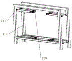
图2为第一支架结构示意图;Fig. 2 is a schematic diagram of a first support structure;
图3为第一支架折叠示意图;3 is a schematic diagram of the folding of the first bracket;
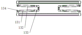
图4为第一支架折叠俯视图;Figure 4 is a top view of the first bracket folded;
图5为第一支架展开俯视图;FIG. 5 is a top view of the first bracket being unfolded;
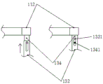
图6为单轴伸缩铰链变化对照图;Figure 6 is a comparison diagram of the change of the uniaxial telescopic hinge;
图7为双轴伸缩铰链结构示意图;FIG. 7 is a schematic structural diagram of a biaxial telescopic hinge;
图8为双轴伸缩铰链变化对照图;Figure 8 is a comparison diagram of the change of the biaxial telescopic hinge;
图9为第二支架结构俯视图;9 is a top view of the second support structure;
图10为内嵌式角连接件结构示意图;FIG. 10 is a schematic structural diagram of an embedded corner connector;
图11为支撑杆与内嵌式角连接件连接示意图;Figure 11 is a schematic diagram of the connection between the support rod and the built-in corner connector;
图中:1-第一支架,11-立杆,111-A类立杆,112-B类立杆,12-连接杆,13-折叠连杆,131-第一横杆,1311-第一条形孔,132-第二横杆,1321-第二条形孔,133-双轴伸缩铰链,1331-第一螺丝,1332-第二螺丝,134-单轴伸缩铰链,1341-第三螺丝,2-第二支架,21-支撑杆,211-通孔,22-内嵌式角连接件,221-第四螺丝。In the picture: 1-first bracket, 11-pole, 111-type A pole, 112-type B pole, 12-connecting rod, 13-folding link, 131-first crossbar, 1311-first Bar hole, 132-Second cross bar, 1321-Second bar hole, 133-Dual-axis telescopic hinge, 1331-First screw, 1332-Second screw, 134-Single-axis telescopic hinge, 1341-Third screw , 2-Second bracket, 21-Support rod, 211-Through hole, 22-Embedded corner connector, 221-The fourth screw.
具体实施方式Detailed ways
依据本申请的上述结构特点,对本申请的实施方式做进一步说明:According to the above-mentioned structural features of the application, the embodiments of the application are further described:
参照图1~11,本实施例提供一种便携式高稳定性折叠货架,包括第一支架1与第二支架2,第一支架1上表面与第二支架2下底面连接。1 to 11 , the present embodiment provides a portable high-stability folding shelf, including a
第一支架1包括立杆11、连接杆12与折叠连杆13;立杆11包括至少两根A类立杆111与至少两根B类立杆112,所述两根A类立杆111之间通过连接杆12固定连接,两根B类立杆112之间通过连接杆12固定连接;A类立杆111与B类立杆112之间通过折叠连杆13连接;所述折叠连杆13包括第一横杆131、第二横杆132、双轴伸缩铰链133与单轴伸缩铰链134;第一横杆131与第二横杆132通过双轴伸缩铰链133连接;单个双轴伸缩铰链133与不少于两个第一螺丝1331、不少于两个第二螺丝1332均分别通过螺纹连接,第一横杆131与第二横杆132均分别设有第一条形孔1311,且第一螺丝1331分别位于第一条形孔1311内或第一条形孔1311正下方;第一横杆131与双轴伸缩铰链133、第二横杆132与双轴伸缩铰链133均分别通过第一螺丝1331的螺柱底端压接;第一横杆131与A类立杆111、第二横杆132与B类立杆112均分别通过单轴伸缩铰链134连接;单个单轴伸缩铰链134与不少于一个第三螺丝1341通过螺纹连接,第一横杆131与第二横杆132均分别设有第二条形孔1321,第三螺丝1341位于位于第二条形孔1321内或第二条形孔1321正下方;第一横杆131与A类立杆111、第二横杆132与B类立杆112均分别通过第三螺丝1341的螺柱底端压接。The
第二支架2包括不少于四个支撑杆21与不少于四个内嵌式角连接件22,且所述支撑杆211首尾依次通过内嵌式角连接件22连接成环形或U形;单个内嵌式角连接件22与不少于两个第四螺丝221通过螺纹连接;单根支撑杆21两端分别设有通孔211,所述第四螺丝221位于通孔211内或通孔211正下方;所述支撑杆21与内嵌式角连接件22分别通过第四螺丝221的螺柱底端压接。The
所述第一横杆131与第二横杆132均为全空心管结构或两端局部空心管结构。所述支撑杆21为全空心管结构或两端局部空心管结构。所述第一条形孔1311、第二条形孔1321均为通孔结构。所述第一螺丝1331、第二螺丝1332、第三螺丝1341与第四螺丝221均为无头螺丝。The
工作原理:运输时,第一支架1处于折叠状态(如图3、图4所示),第二支架2处于未装配状态(即所有支撑杆21自身之间未连接、支撑杆21与隐藏式角连接件22之间未连接、隐藏式角连接件22与第四螺丝221之间未连接),通过减小占空性来便于远距离运输,同时便于通过楼梯/电梯进行上下楼的搬运。到达使用场地后,首先通过螺丝刀(或同类工具)将第二支架2装配至一个整体,然后将第一支架1展开至第一横杆131、第二横杆132、双轴伸缩铰链133与单轴伸缩铰链134位于同一直线(如图2所示);再然后使用螺丝刀(或同类工具)松开所有的第一螺丝1331和第三螺丝1341,将A类立杆111与B类立杆112向内推动,使得双轴伸缩铰链133回缩至第一横杆131与第二横杆132内腔(如图8所示)、单轴伸缩铰链134回缩至第一横杆131或第二横杆132内腔(如图6所示),再次使用螺丝刀(或同类工具)将所有第一螺丝1331、第二螺丝1332、第三螺丝1341拧紧,实现第一支架1结构的固定,增强稳定性;最后,将第二支架2放置或使用螺栓安装在第一支架1上方,在第二支架2内铺设底板,实现整个货架的装配与加固。Working principle: During transportation, the
本发明的描述中,需要说明的是,术语“上”、“下”、“左”、“右”等指示的方位或者位置关系为基于附图所示的方位或者位置关系,仅是为了便于描述本发明和简化描述,而不是指示或者暗示所指的装置或者元件必须具有特定的方位,以特定的方位构造和操作,因此不能理解为对本发明的限制。In the description of the present invention, it should be noted that the orientations or positional relationships indicated by the terms "upper", "lower", "left", "right", etc. are based on the orientations or positional relationships shown in the accompanying drawings, which are only for convenience The invention is described and simplified, rather than indicating or implying that the device or element referred to must have a particular orientation, be constructed and operate in a particular orientation, and therefore should not be construed as limiting the invention.
本发明的描述中,还需要说明的是,除非另有明确的规定和限制,术语“设置”、“安装”、“连接”应做广义理解,例如,可以是固定连接,也可以是可拆卸连接,或一体地连接,可以是机械连接,也可以是电连接,可以是直接连接,也可以是通过中间媒介相连,可以是两个元件内部的连通。对于本领域的普通技术人员而言,可以根据具体情况理解上述术语在本发明中的具体含义。In the description of the present invention, it should also be noted that, unless otherwise expressly specified and restricted, the terms "arrangement", "installation" and "connection" should be understood in a broad sense, for example, it may be a fixed connection or a detachable connection The connection, or the integral connection, can be a mechanical connection, an electrical connection, a direct connection, or a connection through an intermediate medium, or the internal communication between the two elements. For those of ordinary skill in the art, the specific meanings of the above terms in the present invention can be understood according to specific situations.
综上所述,对于本领域的技术人员,依据本发明的指导,在不脱离本发明的原理与精神的前提下,对本发明所做的改变、修改、替换、变形仍落入本发明的保护范围内。To sum up, for those skilled in the art, according to the guidance of the present invention, under the premise of not departing from the principle and spirit of the present invention, changes, modifications, replacements and deformations made to the present invention still fall within the protection of the present invention within the range.
Claims (5)
Priority Applications (1)
| Application Number | Priority Date | Filing Date | Title |
|---|---|---|---|
| CN202011217807.2A CN112137319A (en) | 2020-11-04 | 2020-11-04 | Portable high-stability folding goods shelf |
Applications Claiming Priority (1)
| Application Number | Priority Date | Filing Date | Title |
|---|---|---|---|
| CN202011217807.2A CN112137319A (en) | 2020-11-04 | 2020-11-04 | Portable high-stability folding goods shelf |
Publications (1)
| Publication Number | Publication Date |
|---|---|
| CN112137319A true CN112137319A (en) | 2020-12-29 |
Family
ID=73953857
Family Applications (1)
| Application Number | Title | Priority Date | Filing Date |
|---|---|---|---|
| CN202011217807.2A Pending CN112137319A (en) | 2020-11-04 | 2020-11-04 | Portable high-stability folding goods shelf |
Country Status (1)
| Country | Link |
|---|---|
| CN (1) | CN112137319A (en) |
Cited By (1)
| Publication number | Priority date | Publication date | Assignee | Title |
|---|---|---|---|---|
| WO2025199287A1 (en) * | 2024-03-20 | 2025-09-25 | Global Industrial Distribution Inc. | Kitted pallet rack upright frames |
Citations (8)
| Publication number | Priority date | Publication date | Assignee | Title |
|---|---|---|---|---|
| CN201963675U (en) * | 2011-03-28 | 2011-09-07 | 湖州立方新材料有限公司 | Embedded rabbet |
| CN202981185U (en) * | 2012-12-17 | 2013-06-12 | 福州市仓山区博阳贸易有限公司 | Multifunctional telescopic combined folding storage rack |
| CN203137674U (en) * | 2013-06-07 | 2013-08-21 | 吴佳 | Folding stool |
| CN205197370U (en) * | 2015-11-02 | 2016-05-04 | 浙江泰普森创意设计有限公司 | Retractable folding table |
| CN209769547U (en) * | 2018-11-21 | 2019-12-13 | 顺丰科技有限公司 | Collapsible and reusable stand |
| CN212815100U (en) * | 2020-07-20 | 2021-03-30 | 贵州贵昌金属制品有限公司 | Foldable goods shelf |
| CN213849567U (en) * | 2020-11-04 | 2021-08-03 | 安保国 | A portable high-stability folding shelf |
| CN215226438U (en) * | 2021-04-21 | 2021-12-21 | 国网江苏省电力有限公司无锡供电分公司 | foldable shelf |
-
2020
- 2020-11-04 CN CN202011217807.2A patent/CN112137319A/en active Pending
Patent Citations (8)
| Publication number | Priority date | Publication date | Assignee | Title |
|---|---|---|---|---|
| CN201963675U (en) * | 2011-03-28 | 2011-09-07 | 湖州立方新材料有限公司 | Embedded rabbet |
| CN202981185U (en) * | 2012-12-17 | 2013-06-12 | 福州市仓山区博阳贸易有限公司 | Multifunctional telescopic combined folding storage rack |
| CN203137674U (en) * | 2013-06-07 | 2013-08-21 | 吴佳 | Folding stool |
| CN205197370U (en) * | 2015-11-02 | 2016-05-04 | 浙江泰普森创意设计有限公司 | Retractable folding table |
| CN209769547U (en) * | 2018-11-21 | 2019-12-13 | 顺丰科技有限公司 | Collapsible and reusable stand |
| CN212815100U (en) * | 2020-07-20 | 2021-03-30 | 贵州贵昌金属制品有限公司 | Foldable goods shelf |
| CN213849567U (en) * | 2020-11-04 | 2021-08-03 | 安保国 | A portable high-stability folding shelf |
| CN215226438U (en) * | 2021-04-21 | 2021-12-21 | 国网江苏省电力有限公司无锡供电分公司 | foldable shelf |
Cited By (1)
| Publication number | Priority date | Publication date | Assignee | Title |
|---|---|---|---|---|
| WO2025199287A1 (en) * | 2024-03-20 | 2025-09-25 | Global Industrial Distribution Inc. | Kitted pallet rack upright frames |
Similar Documents
| Publication | Publication Date | Title |
|---|---|---|
| CN203977831U (en) | A kind of scaffold base | |
| CN202248840U (en) | Disc buckle type supporting structure | |
| US20060169312A1 (en) | Trut frame of a tent | |
| CN213849567U (en) | A portable high-stability folding shelf | |
| CN210598077U (en) | Recyclable construction engineering scaffold | |
| CN208965808U (en) | Board connection structure of composite partition wall | |
| CN222861010U (en) | A foldable standard section | |
| CN201641001U (en) | Foldable rack | |
| CN216822353U (en) | Combined article-placing shelf | |
| CN217631121U (en) | A single-adjustable height-adjustable unbalanced scaffold | |
| CN216552693U (en) | Large-span assembly type building crossbeam | |
| CN216494054U (en) | Portable table with foldable supporting structure | |
| CN222686060U (en) | A convenient and simple bracket | |
| CN110657334B (en) | Total station tripod stabilizing device, system and method | |
| CN209975973U (en) | A scaffold connection structure for exterior wall construction | |
| CN209195095U (en) | A kind of folding stage truss | |
| CN209474040U (en) | A foldable shelf | |
| CN206607424U (en) | A kind of foldable clothes hanger and clothing external member of drying in the air | |
| CN212460984U (en) | Warning sign is used in municipal construction convenient to carry | |
| CN211703908U (en) | Multifunctional storage rack for hotel guest rooms | |
| CN208491366U (en) | An easy-to-assemble shelf bench | |
| CN211817932U (en) | A high-strength wear-resistant plastic building formwork | |
| CN212765457U (en) | A combination drawing board for planar design | |
| CN207317234U (en) | A kind of folding portable air conditioner support | |
| CN218571705U (en) | Furniture dismounting frame structure based on thread telescopic principle |
Legal Events
| Date | Code | Title | Description |
|---|---|---|---|
| PB01 | Publication | ||
| PB01 | Publication | ||
| SE01 | Entry into force of request for substantive examination | ||
| SE01 | Entry into force of request for substantive examination | ||
| RJ01 | Rejection of invention patent application after publication | ||
| RJ01 | Rejection of invention patent application after publication |
Application publication date: 20201229 |